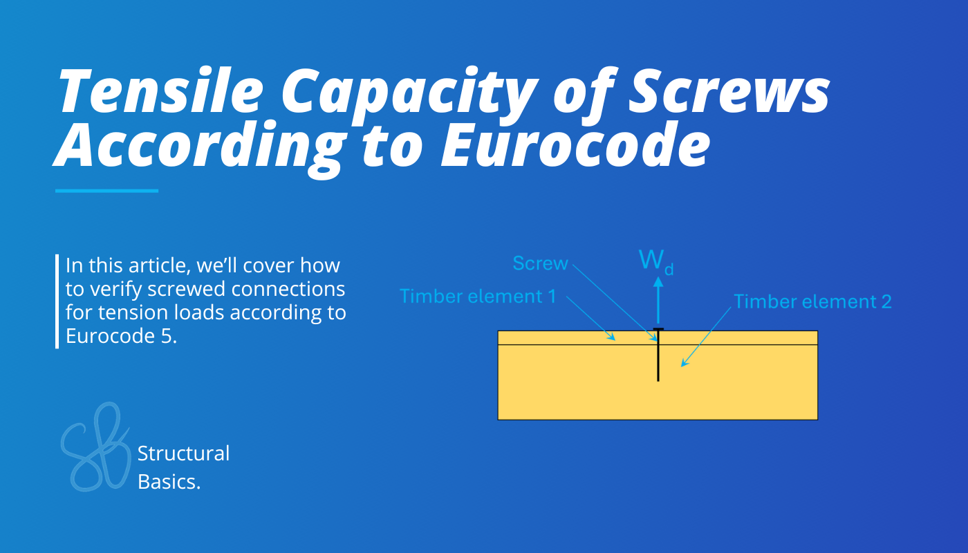
Tensile Capacity of Screws {Eurocode Tutorial}
In timber structures screws are often used to connect 2 timber elements like a timber rafter with a timber purlin or OSB boards with studs.
In this article, you’ll learn how to verify screwed timber connections for axial loads according to Eurocode.
Now, let’s get into it.
The 4 Steps To Calculate The Tensile Capacity of Screws According To Eurocode
The axial capacity of screws is calculated according to EN 1995-1-1 8.7.2 and the following failure modes should be investigated:
– the withdrawal capacity of the threaded part of the screw
– for screws used in combination with steel plates, the tear‑off capacity of the screw head should be greater than the tensile strength of the screw
– the pull‑through strength of the screw head
– the tension strength of the screw
– the screws used in conjunction with steel plates, failure along the circumference of a group of screws (block shear or plug shear
Failure modes 2 and 4 should never happen as manufacturer do extensive testing to bring their screws to market. At least I have never met any structural engineer do this verification.
Failure mode 5 should not happen if you fulfill the minimum spacing requirements of EN 1995-1-1 Table 8.6.
Therefore we are left with 2 verifications or in other words 2 capacities to calculate:
- withdrawal capacity and
- pull-through strength of the screw head
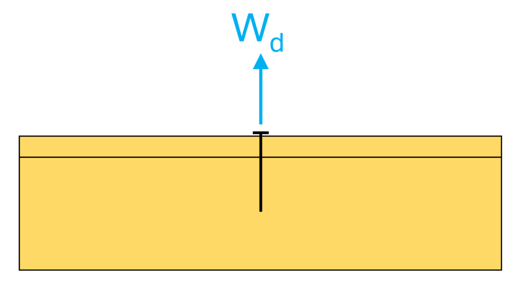
In this newsletter, we’ll calculate the axial capacity of the screwed connection below.
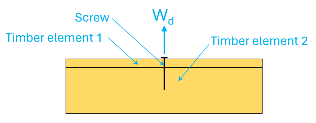
Step #1: Define the geometrical properties of the screws and timber elements
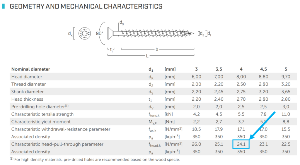
As a screw we use the fully threaded countersunk screw HTS from Rotho Blaas. Rotho Blaas is an international manufacturer of screws and their screws are commonly used in Europe. You can find the data here. The elements and screw have the following dimensions:
- Timber element 1 (OSB): tosb=t1=20mm
- Screw length: ln=50mm
- Pointside penetration thickness in single shear connections (EN1995-1-1 8.3.1.1): t2=ln-tosb=30mm
- Screw diameter d=2.5mm
- Screw head diameter dh=8.0mm
Step #2: Define the material properties of the timber element
Here are the strength and stiffness properties that we need in the calculation:
- Density OSB: ρk.osb=550 kg/m3
- Density timber rafter: ρk.r=350 kg/m3
The partial safety factor is found in EN 1995-1-1 Table 2.3 as:
γM = 1.3
The timber elements are classified according to EN 1995-1-1 2.3.1.3 as service class 2 (assumption in this tutorial).
Then we’ll verify the timber beam for a design load of load duration class short-term (EN 1995-1-1 Table 2.1) which leads to a modification factor (EN 1995-1-1 Table 3.1) of:
kmod = 0.9
Step #3: Calculate the loads acting on the screw
In this step we need to calculate the characteristic loads that act on the connector. The characteristic area loads are applied to the slabs like the OSB board and transfered to the connection.
We won’t show how to calculate the loads and how to do the load transfer in this newsletter, as each calculation of the individual load is an article for itself and load transfer is also a big topic.
If you want to learn how to transfer loads correctly from one element like the OSB board to connections like the screws, then I recommend you to check out Module #2. Defining and transfering loads is explained in detail.
→ Click here to read more about it. ←
In this email, we’ll verify the screw for the following point load.
Wk = 0.85 kN
Step #4: Axial design verification of the screw
Before jumping into the calculation I just quickly talk a bit about how you verify connectors in “real life” and which formulas you use.
In reality I mostly go to the manufacturers homepage, pick a screw or nail and look up the shear and tensile capacity from there capacity tables.
If I verify the connectors by hand, I usually pick a product and look up the verification formulas from their ETA declaration. Every load bearing timber connector needs to have an ETA declaration. Otherwise you can’t use them for structural purposes.
As you will see in the calculation below, not all formulas are included in Eurocode (in our case the head-pull capacity). But these formulas are included in the ETA. The formulas also verify sometimes from the ones in Eurocode.
Just know that it’s ok to use the formulas from the ETA declaration.
| Characteristic embedment strength for OSB board (EN1995-1-1 (8.39)): | fax.k.1 = 3.6 ⋅ 10-3 ⋅ ρk.osb1.5/(1.5 ⋅ cos(90°) + sin(90°)) N/mm2 = 46.4 N/mm2 |
| Characteristic embedment strength for timber element 2 – rafter (EN1995-1-1 (8.39)): | fax.k.2 = 3.6 ⋅ 10-3 ⋅ ρk.osb1.5/(1.5 ⋅ cos(90°) + sin(90°)) N/mm2 = 23.6 N/mm2 |
| Minimum density of the 2 timber element: | ρk = min(ρk.osb; ρk.r) = 350 kg/m3 |
| Penetration length minus diameter: | lef = t2 – d = 27.5 mm |
| Characteristic withdrawal resistance of screws (EN1995-1-1 (8.25)): | Fax.Rk = min(fax.k.1, fax.k.2) (π ⋅ d ⋅ lef)0.8 = 1.74 kN |
| Head pull-through resistance of the screw (given in the datasheet; according to EN 1995-1-1 8.7.2 (6) the pull-through capacity must be determined by tests): | fhead.k = 24.1 N/mm2 |
| Head pull-through capacity (ETA 11/0030): | Fax.head.k = fhead.k ⋅ dh2 ⋅ ρk.r0.8 = 1.44 kN |
| Characteristic axial capacity: | Fax.Rk = min(Fax.Rk; Fax.head.k) = 1.44 kN |
| Design withdrawal capacity: | Fax.Rd = kmod ⋅ Fax.Rk/γM = 1.0 kN |
Verification:
η = Wd/Fax.Rd = 0.85
Final words
Alright, this is how design and verify screws for axial loads according to Eurocode.
Hope this article helped.
If you don’t want to miss any new structural design tutorials, then subscribe to our free weekly newsletter.
Or subscribe to my YouTube channel for regular updates.
Let’s design better structures together,
Laurin.

Laurin Ernst
![Rafter Roof Design [Step-By-Step Guide]](https://www.structuralbasics.com/wp-content/uploads/2022/04/Rafter-Roof-Design-1-768x439.jpg)