Reinforced Concrete Column Design [2026]
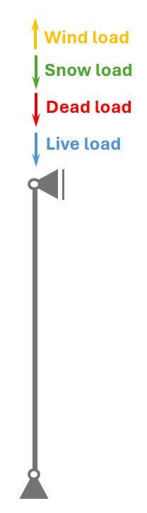
Reinforced concrete columns resist vertical loads that act on a building such as wind, snow, dead and live load. The columns then transfer these loads to the foundations.
In this guide, we’ll show step-by-step, how you design reinforced concrete columns according to EN 1992-1-1.
Not much more talk, let’s dive into it.
Example RC Column
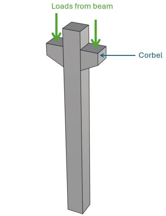
We are showing all calculation steps for the following reinforced concrete column with corbels. 👇👇
The corbels are used to support beams which support slabs. It’s a good example, because the loads on the corbels emphasize the effects of eccentricities.
Process of Reinforced Concrete Column Design
Before we dive into the nerdy calculations, it’s good to get an overview of the steps that need to be taken to design a reinforced concrete column – in this case, an axially loaded column.
- Calculate characteristic loads that act on the concrete column
- Load combinations to calculate the design loads
- Define properties of concrete and reinforcement
- ULS bending and compression verification
However, we dive a bit deeper and explain concepts, such as different static systems of columns along the way.
1. Static System Of The Column
There is a variety of different static systems that the structural engineer can choose from, and often the columns act together with beams or slabs as frames.
In this tutorial, we use a simply supported column/beam as the static system. The horizontal loads are resisted by shear walls. Therefore only vertical loads act on the column.
Simply Supported Column
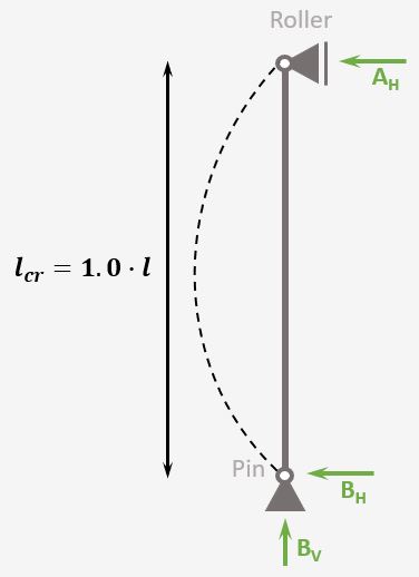
Support types
Roller & Pin
Reactions
Roller: Horizontal
Pin: Vercial & Horizontal
Buckling length
$l_{cr} = 1.0 \cdot l$
It’s important to know about the different static systems, since each type of column has a different buckling length, which influences the buckling resistance significantly. ❗❗
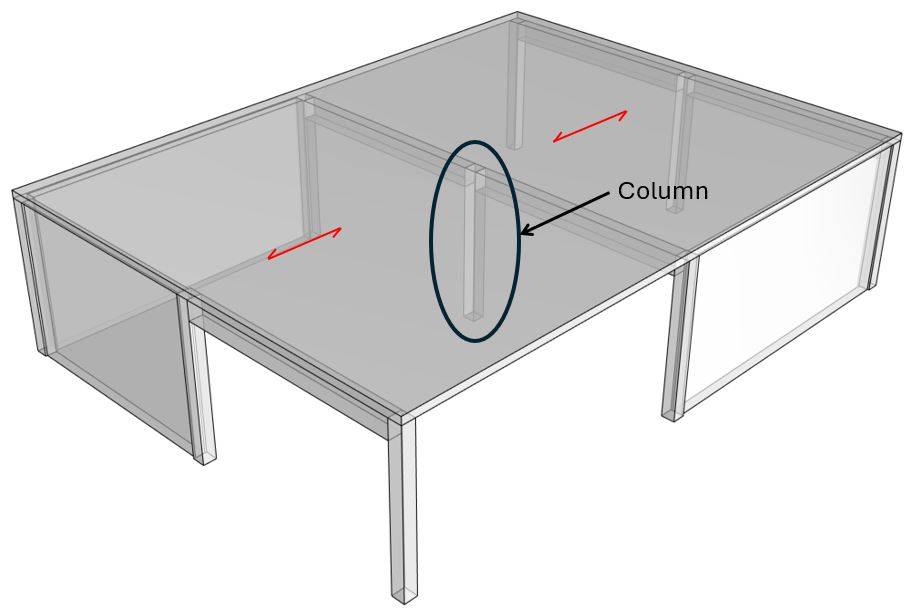
For this tutorial, we assume to design a simply supported column on the inside of a building structure.
The following picture shows where the column is placed.
2. Characteristic Loads Of RC Column
The loads of a structure depend on its location, geometry, building type and other factors.
We’ll assume in this tutorial that we design the column of a 1-storey building.
Now on a 1-storey building, the following loads act:
- Dead load of structural and non-structural elements
- Live load of the roof
- Snow load and
- Wind load
We’ll do a lot of assumptions in this tutorial, but if you want to learn more about loads on roofs, you can check out this article.
Load transfer
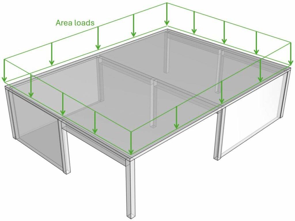
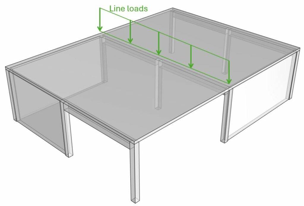
❗ The following load transfer explanation works if the building is a traditional structure with simply supported beams, columns and slabs.❗
- Live, Snow, Wind and dead load (self-weight of roofing) are applied as area loads [kN/m2] on the roof/slab.
- By multiplying the area loads (live, snow, wind, dead load) with the spacing of the beams, line loads are calculated. These line load can now be applied to the beams.
- The center reaction forces of the beam system is then the characteristic vertical load that is applied to the column.
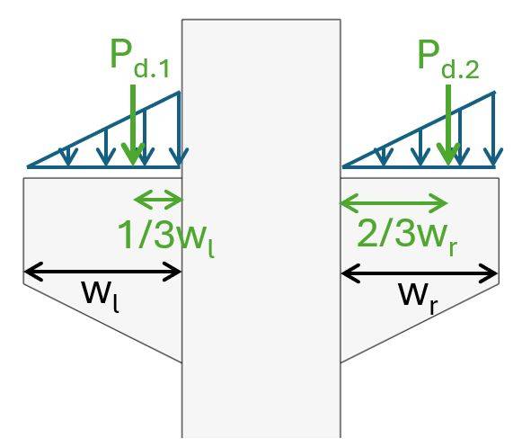
But as we design a column with corbels, we have to consider the excentricities and therefore seperate the loads on the right and left corbel.
The following characteristic load values are assumptions and we’ll only look at the dead and live load.
Left corbel:
| $g_{k}$ | 110 kN | Characteristic value of dead load |
| $q_{k}$ | 30 kN | Characteristic value of live load |
Right corbel:
We’ll design the column for the most critical loading situation, which happens when the live load is set to 0 on one of the spans.
| $g_{k}$ | 110 kN | Characteristic value of dead load |
| $q_{k}$ | 0 kN | Characteristic value of live load |
Be aware that you should also include the dead load of the column. For simplicity reasons, we don’t do that in this tutorial.
❗
The characteristic values of loads depend on a lot of different factors like location, National Annex and geometry of the building and roof to name just a few. Loads therefore need to be calculated for every structure.
3. Load combinations
Load combinations combine several load cases and multiply the characteristic loads with safety factors.
Luckily we have already written an extensive article about what load combinations are and how we use them. In case you need to brush up on it, you can read the blog post here.
ULS Load combinations
| LC1 – right corbel | $P_{d.2} = 1.35 \cdot 110 kN + 1.5 \cdot 30 kN$ | $P_{d.2} = 193.5 kN$ | |
| LC1 – left corbel | $P_{d.1} = 1.35 \cdot 110 kN + 1.5 \cdot 0 kN$ | $P_{d.1} = 148 kN$ |
SLS Quasi permanent load combinations
We need the quasi-permanent loads later on to calculate a factor that takes creep into account. We’ll use a $\psi_2$ factor of 0.2 which is the value for offices in Denmark.
| LC1 – right corbel | $P_{qp.2} = 110 kN + \psi_{2} \cdot 30 kN$ | $P_{qp.2} = 116 kN$ | |
| LC1 – left corbel | $P_{qp.1} = 110 kN + \psi_{2} \cdot 0 kN$ | $P_{qp.1} = 110 kN$ |
4. Concrete And Reinforcement Properties
We’ll use the material properties from eurocodeapplied.com.
Here are the material properties we are going to use.
| Concrete compression strength | $f_{c.k}= 30 MPa$ |
| Concrete tensile strength | $f_{ctm}=2.9 MPa$ |
| Partial factor in-situ concrete (Denmark) | $\gamma_c = 1.45$ |
| Design concrete compression strength | $f_{c.d}=\frac{f_{c.k}}{\gamma_c} = 20.7 MPa$ |
| Concrete cover | $c_c = 25 mm$ |
| Reinforcement yield strength | $f_{y.k} = 500 MPa$ |
| Partial factor for reinforcement (Denmark) | $\gamma_s = 1.2$ |
| Design yield strength | $f_{y.d}=\frac{f_{y.k}}{\gamma_s} = 416.7 MPa$ |
| E-modulus reinforcement | $E_{s} = 200000 MPa$ |
| Diameter stirrups | $d_{s.v} = 10 mm$ |
Now, we are set to design the reinforced concrete column. 🔥🔥
5. ULS Bending Moment Verification
In the ULS design of the reinforced concrete column, we’ll first calculate the bending moment of the column due to eccentricities and imperfections, then check if second order effects have to be considered, and finally we use moment/normal force tables to find the required reinforcement.
As a structural engineer, I never calculate and verify an RC column step-by-step, as we’ll show below. Instead, I use software or an Excel spreadsheet. This speeds up the design a lot. However, I recommend going through the calculation at least once to understand all parameters that have an influence on the design.
Bending moment due to eccentricities and imperfections
First, let’s calculate the bending moment due to the eccentricities of the loads on the corbels. We’ll look at the worst case scenario, where we assume that the loads are distributed on the corbel as triangular loads and the smaller load has its resultant closer to the centreline of the column.
Geometry of the column
| Cross-sectional width | w = 300 mm |
| Cross-sectional height | h = 200 mm |
| Width of corbel (right) | wr = 300 mm |
| Width of corbel (left) | wl = 300 mm |
Now, we can calculate the eccentricities of Pd.1 and Pd.2.
| Eccentricity of Pd.1 | el = 1/3 wl + w/2= 0.25m |
| Eccentricity of Pd.2 | er = 2/3 wr + w/2= 0.35m |
The bending moment due to these eccentricities is calculated as:
| Design bending moment | $M_d = P_{d.2} \cdot e_r – P_{d.1} \cdot e_l = 30.7 kNm$ |
| Quasi-permanent bending moment | $M_{qp} = P_{qp.2} \cdot e_r – P_{qp.1} \cdot e_l = 21.5 kNm$ |
Next, we’ll calculate the bending moment due to imperfections according to EN 1992-1-1 5.2.
| Buckling length (simply supported column) | $l_0 = l = 3.5 m$ |
| Reduction factor for height (EN 1992-1-1 (5.1)) | $\alpha_h = min(\frac{2}{\sqrt{\frac{l_0}{m}}}; 1.0) = 1.0$ |
| Reduction factor for number of elements (EN 1992-1-1 (5.1)) | $\alpha_m = \sqrt{0.5 \cdot (1+ \frac{1}{1})} = 1$ |
| Basic value (EN 1992-1-1 (5) Note) | $\theta_0 = 1/200 = 0.005$ |
| Imperfection (EN 1992-1-1 (5.1)) | $\theta_i = \theta_0 \cdot \alpha_m \cdot \alpha_h = 0.005$ |
| Eccentricity for isolated members (EN 1992-1-1 (5.2)) | $e_i = \frac{\theta_0 \cdot l_0}{2} = 0.875 cm$ |
| Moment due to imperfection | $M_i = (N_{d.1} + N_{d.2}) \cdot e_i = 2.99 kNm$ |
| Total moment due to eccentricities | $M_{Ed} = M_d + M_i = 33.71 kNm$ |
Check if second order effects may be ignored (EN 1992-1-1 5.8.3)
| Notional size (EN 1992-1-1 3.1.4 (5)) | $h_0 = \frac{2 \cdot w \cdot h}{2w + 2h} = 150 mm$ |
| Creep coefficient (EN 1992-1-1 Figure 3.1) | $\varphi_{t0} = 2.3$ |
| Effective creep ratio (EN 1992-1-1 5.8.4) | $\varphi_{ef} = \varphi_{t0} \cdot \frac{M_{qp}}{M_{Ed}} = 1.47$ |
| Factor (EN 1992-1-1 5.13N) | $A = \frac{1}{1+0.2 \cdot \varphi_{ef}} = 0.77$ |
| Diameter of rebars | $d_s = 25 mm$ |
| Amount of rebars per layer | $n = 2$ |
| Reinforcement area | $A_s = \frac{d_s^2}{4} \cdot \pi \cdot n \cdot 2 = 1963.5 mm^2$ |
| Mechanical reinforcement ratio (EN 1992-1-1 5.13N) | $\omega = \frac{A_s \cdot f_{yd}}{w \cdot h \cdot f_{cd}} = 0.44$ |
| Factor (EN 1992-1-1 5.13N) | $B = \sqrt{1 + 2 \cdot \omega} = 1.37$ |
| Factor (EN 1992-1-1 5.13N) | $C = 0.7$ |
| Relative normal force (EN 1992-1-1 5.13N) | $n = \frac{N_{d.1} + N_{d.2}}{w \cdot h \cdot f_{cd}} = 0.18$ |
| Slenderness (EN 1992-1-1 (5.13N)) | $\lambda_{lim} = A \cdot B \cdot C \cdot 20 \cdot \frac{1}{\sqrt{n}} = 34.65$ |
| Radius of gyration of uncracked section | $i = \sqrt{\frac{h^3 \cdot w}{12 \cdot h \cdot w}} = 0.087 m$ |
| Slenderness ratio (EN 1992-1-1 (5.14)) | $\lambda = l_0/i = 40.41$ |
| Check if second order effects need to be included: | $\lambda > \lambda_{lim} = 1$ |
Yes, second order effects have to be included.
Method based on nominal curvature (EN 1992-1-1 5.8.8)
| Value of n at max. moment resistance (EN 1992-1-1 (5.36)) | $n_{bal} = 0.4$ |
| Relative axial force (EN 1992-1-1 (5.36)) | $n = \frac{N_d}{w \cdot h \cdot f_{cd}}$ |
| (EN 1992-1-1 (5.36)) | $n_u = 1 + \omega = 1.44$ |
| Correction factor depending on axial load (EN 1992-1-1 (5.36)) | $K_r = min(\frac{n_u-n}{n_u – n_{bal}}, 1.0) = 1.0$ |
| Diameter of rebars | $\epsilon_{yd} = \frac{f_{yd}}{E_s} = 0.0021$ |
| Effective depth of rebars | $d = h – c_c – d_{s.v} – \frac{d_s}{2} = 252.5 mm$ |
| (EN 1992-1-1 (5.36)) | $1/r_0 = \frac{\epsilon_{yd}}{0.45 \cdot d} = 0.0183 1/m$ |
| (EN 1992-1-1 (5.37)) | $\beta = 0.35 + \frac{f_{ck}}{200 MPa} – \frac{\lambda}{150} = 0.23$ |
| Factor for taking into account creep (EN 1992-1-1 (5.37)) | $K_{\varphi} = max(1 + \beta \cdot \varphi_{ef}, 1.0)$ |
| Curvature (EN 1992-1-1 (5.34)) | $1/r = K_{r} \cdot K_{\varphi} \cdot 1/r_0 = 0.025 1/m$ |
| Factor depending on the curvature distribution (EN 1992-1-1 5.8.8.2 (4)) | $c = 10$ |
| Deflection (EN 1992-1-1 (5.33)) | $e_{2} = 1/r \cdot \frac{l_0^2}{c} = 0.03m$ |
| Nominal second order moment (EN 1992-1-1 (5.33)) | $M_2 = N_d \cdot e_2 = 10.26 kNm$ |
Design of reinforcement
We’ll use M-N diagrams to find the required reinforcement to take up the bending moments and normal forces acting in the column.
| Design moment | $M_{Ed} = M_{Ed} + M_2 = 43.98 kNm$ |
| Design normal force | $N_d = 341.5 kN$ |
| Distance rebar from edge | $d_1 = c_c + d_{s.v} + \frac{d_s}{2} = 0.048 m$ |
We’ll use a M-N diagram from [1] for d1/h = 0.16 and fck < 50 MPa, where we have to calculate the ratios $\frac{N_d}{w \cdot h \cdot f_{cd}}$ and $\frac{M_{Ed}}{w \cdot h^2 \cdot f_{cd}}$
| Ratio | $\frac{N_d}{w \cdot h \cdot f_{cd}} = 0.183$ |
| Ratio | $\frac{M_{Ed}}{w \cdot h^2 \cdot f_{cd}} = 0.079$ |
Unfortunately, we can’t insert the M-N diagram due to copyright reasons. But you basically find the reinforcement ratio where your 2 lines from $\frac{N_d}{w \cdot h \cdot f_{cd}}$ and $\frac{M_{Ed}}{w \cdot h^2 \cdot f_{cd}}$ intersect.
From [1] Fig. 5.8 we’ll find a reinforcement ratio of $\rho_{tot} = 0.05$. From this ratio we can now calculate the reinforcement of the column.
| Required reinforcement | $A_{s.req} = \rho_{tot} \cdot f_{cd} \cdot h \cdot \frac{w}{f_{yd}} = 223.4 mm^2$ |
| Minimum reinforcement (EN 1992-1-1 9.5.2) | $A_s = max(0.1 \cdot \frac{N_d}{f_{yd}}, 0.002 \cdot w \cdot h) = 180 mm^2$ |
| Utilisation | $\eta = \frac{A_{s.req}}{4 \cdot \pi \cdot (\frac{d_s}{2})^2} = 0.11$ |
11% is a very low utilisation ratio. In this case it would make sense to optimize and decrease the cross-sectional area and the rebar diameter.
Conclusion
Et voilà, the concrete column is verified and dimensioned. 💯💯
If you are new to structural design, then check out more of our design tutorials where you can also learn about other reinforced concrete designs such as
But now, I would like to hear from you: Have you already designed a concrete column in university or at your work? And which semester was that in? Tell us a bit about the structure, as we all want to learn from each other.✍️
References
[1]: A. W. Beeby et al., (2009), Designers’ guide to Eurocode 2: Design of concrete structures
![Timber Truss Roof Design [A Structural Guide]](https://www.structuralbasics.com/wp-content/uploads/2022/04/Timber-Truss-Roof-Design-768x439.jpg)
![What Is A Fillet Weld? [All You Need To Know]](https://www.structuralbasics.com/wp-content/uploads/2023/09/Fillet-weld-768x439.jpg)