5 Loads On Roof Structures
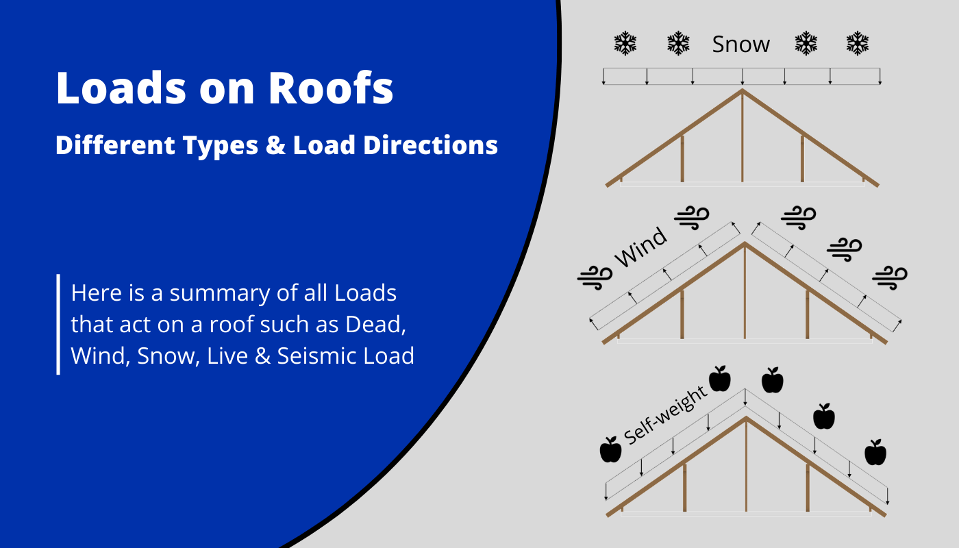
Roofs are exposed to different loads that have to be verified in your structural design calculations.
In this article, we’ll take a closer look at the different types of loads that act on roofs.
Before getting into it. If you want to learn everything you need to know about other loads like the snow load, wind load, dead load, live load or the imperfection load, then I invite you to join my free 8-day email course about loads.
I have also written a very detailed book about load calculation of residential buildings.
We’ll briefly explain each load, show how to apply the load to a static system, and show or refer to other resources that show how to calculate these loads.
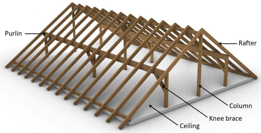
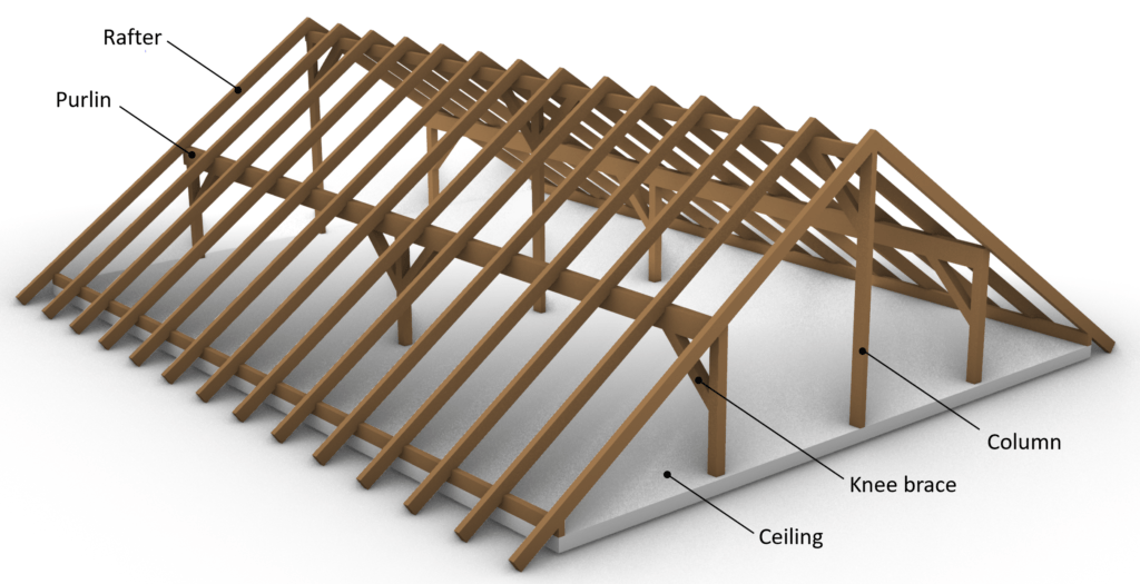
Everything will be visualized on the purlin roof. But it’s applicable to any type of roof.
💡 Info:
This post is focused on roof loading, but loads on other structures are applied and calculated the same way.
So let’s get into it. 🚀🚀
What are area, line and point loads?
So before we are getting into the different loads, we need to talk about some basics first.
Area loads
Area loads are – as the name says – applied on areas, and the unit is kN/m2. Area loads are usually applied on floor slabs, walls and facade elements.
Line loads
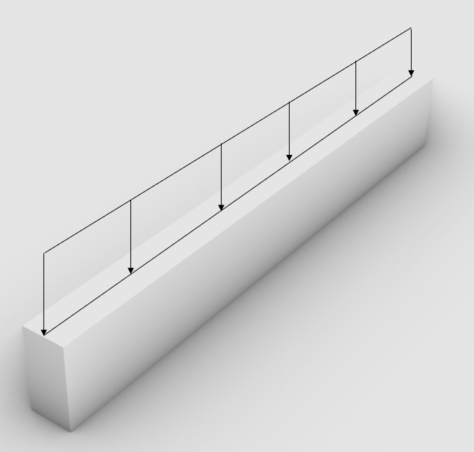
Line loads are applied on beams, columns, walls, rafters, purlins and probably a few more
Point loads
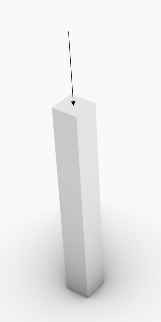
Point loads can be applied on all structural members. For example, the vertical support force of a beam can be applied as a Point load on the column that supports the beam.
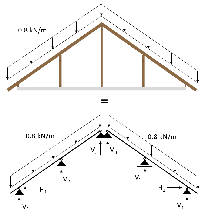
For simplification of the structural calculation, the 3D system and area loads are often transformed in a 2D system and line loads. But let’s look at an example to explain it better 😊
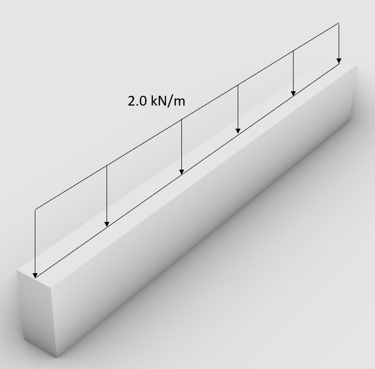
Example of load distribution
We have an area load of 1.0 kN/m2 that is applied on a floor slab. The floor slab is supported by 2 beams. The span of the slab is 4.0 m.
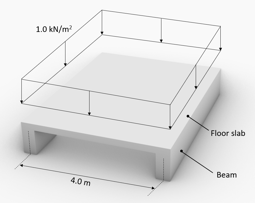
The area load travels through the slab to the 2 beams. Each beam is taking half of the area load. The line load that is acting on 1 beam is calculated like:
$$1.0 \frac{kN}{m^2} \cdot \frac{4m}{2} = 2.0 \frac{kN}{m} $$
This line load can now be applied to the beams.
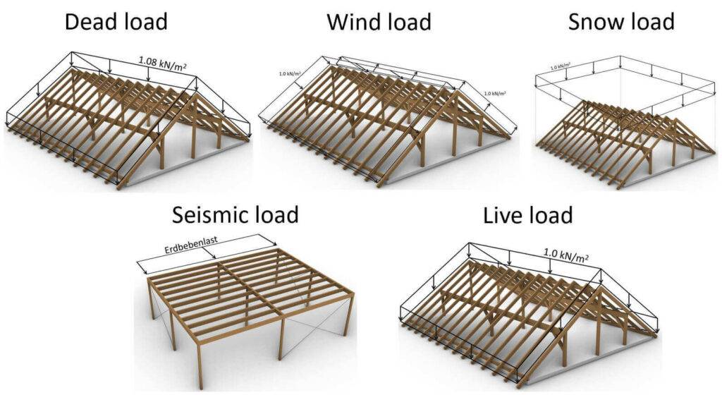
1. Dead load | self-weight
💡
The dead load represents the self-weight of all elements that act on the structure. That includes structural and non-structural elements. In order to get an area load or line load, we need to define the density and dimensions of each element.
So let’s look at a Purlin roof and its roof layers to see how we calculate the area and line dead loads.
The roof layers in the following table are simplified and not all necessary layers are shown.
| Element | Thickness [mm] | Density [kg/m3] | Area load [kN/m2] |
|---|---|---|---|
| OSB board | 20 | 650 | 0.13 |
| Insulation | 300 | 100 | 0.3 |
| Roof tiles | 0.65 | ||
| Sum | 1.08 |
The Area load is calculated as:
Density/100 * Thickness = Area Dead load
For the example of the OSB board:
$$\frac{650}{100} \frac{kg}{m^3} * 0.02 m = 0.13 \frac{kN}{m^2} $$
Now the sum of the dead load (value) can be applied to advanced 3D structural analysis models which can automatically calculate the line loads on the rafters. The loads are applied in 3D, like in the following picture.
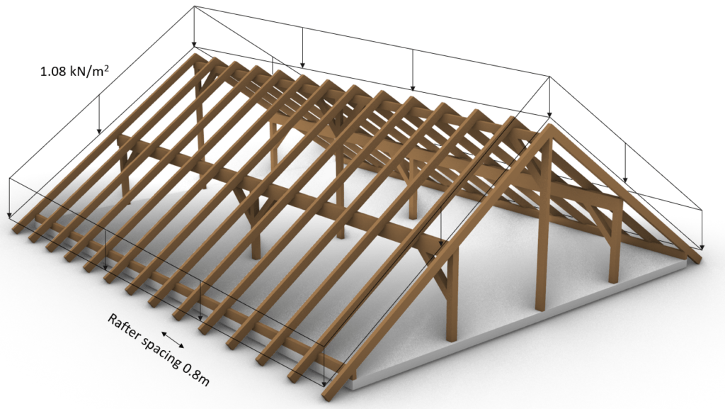
💡
The direction of the load is very important. For the dead load, the direction is always z axis downwards, and it is distributed along the slope of the rafters.
Now if we want to do hand calculations then we need to transform the Area load into a Line load
Area load * Rafter spacing = Line load
$$1.08 \frac{kN}{m^2} * 0.8 m = 0.864 \frac{kN}{m} $$
And add the self-weight of the rafters
Density Rafter/100 * height * width = Dead load rafter
C24 Structural wood is used in this example. Just google something like “C24 structural wood density” to find producers and their technical data sheets.
$$\frac{350}{100} \frac{kg}{m^3} * 0.2 m * 0.1 m = 0.07 \frac{kN}{m} $$
Those 2 line loads can now be added up
$$ 0.864 \frac{kN}{m} + 0.07 \frac{kN}{m} = 0.934 \frac{kN}{m} $$
Which then can be applied to a 2D statical system.
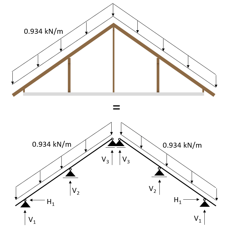
💡
The dead load of 0.934 kN/m that we applied is a characteristic value. We will go further into detail what exactly that means in one of the next blog posts about Load combinations.
2. Wind load
💡
The wind load is the resulting force of the wind that blows on a building or structure.
The calculation of the wind force according to Eurocode is too extensive for this post.
We have written extensive guides with examples on how to calculate the wind load and areas for
- a pitched roof and
- a flat roof.
Make sure to check them out if you need a step-by-step guide.
💡
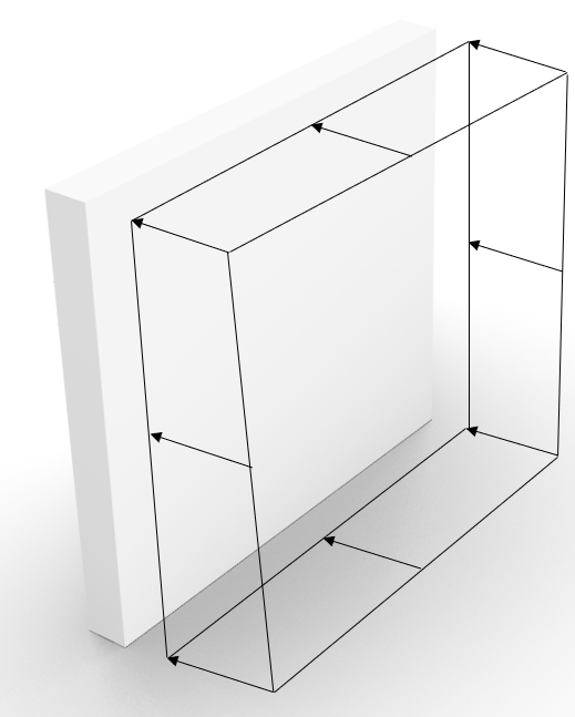
The direction of the wind load is always perpendicular to a building surface like facades, walls, windows and also roofs.
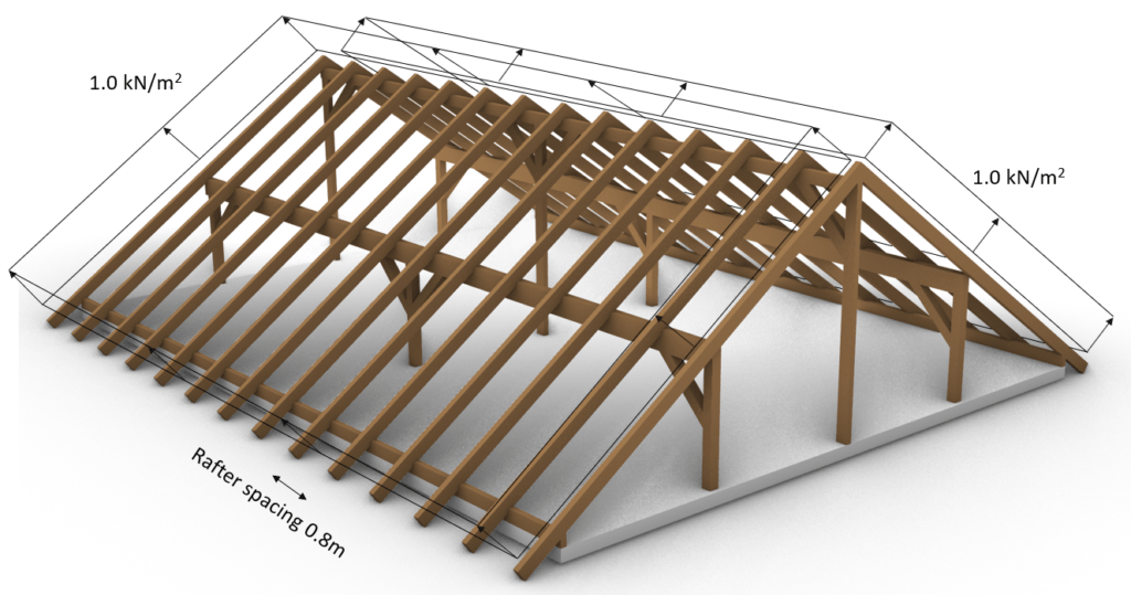
Wind load in 3D system
The wind load in the following figure is very simplified. Usually a roof has different areas with different values of the load, but the purpose of the picture is to emphasize the load direction perpendicular to the rafters.
We assume a wind load of 1.0 kN/m2 that is equally distributed.
Wind load in 2D system
Now if we want to transform the area load into a line load again, then we multiply the area load with the spacing of the rafters:
$$1.0 \frac{kN}{m^2} * 0.8 m = 0.8 \frac{kN}{m^2} $$
And this line load can be applied in a 2D system:
3. Snow load
💡
The snow load is the resulting force of the weight of snow that “lies” on a surface, like a roof.
The snow load is calculated with EN 1991-1-3.
Here are step-by-step guides with examples on how to calculate the snow load of a
Check them out if you want to learn more about the snow load.
But now⌛: Let’s look at how the snow load is applied to structures.
💡
The direction of the snow load is always vertical and like for the dead load z axis downwards. BUT …
The snow load does not follow the slope of a structure. That sounds complicated, I know. So let’s look at an example 😁
Snow load in 3D system
As an example we use a snow load of 1.0 kN/m2 which is used for some constructions in Denmark.
Snow load in 2D system
$$1.0 \frac{kN}{m^2} * 0.8 m = 0.8 \frac{kN}{m^2} $$
And this line load can be applied in a 2D system:
4. Live load
💡
The live load is the resulting force of the weight of things that can change location, but also the weight can change over time. The live load represents for example people or furniture in a building. For the case of a roof structure, this can be the weight of people that do maintenance work on the roof.
The values of the live load can be taken from EN 1991-1-1 Table 6.2 (and National Annex❗) for the different categories of loading areas such as office, roof, balcony, staircase and many more.
I advise you to read up on it in the code to get a better understanding. 📖
So, how is the live load applied to structures?
💡
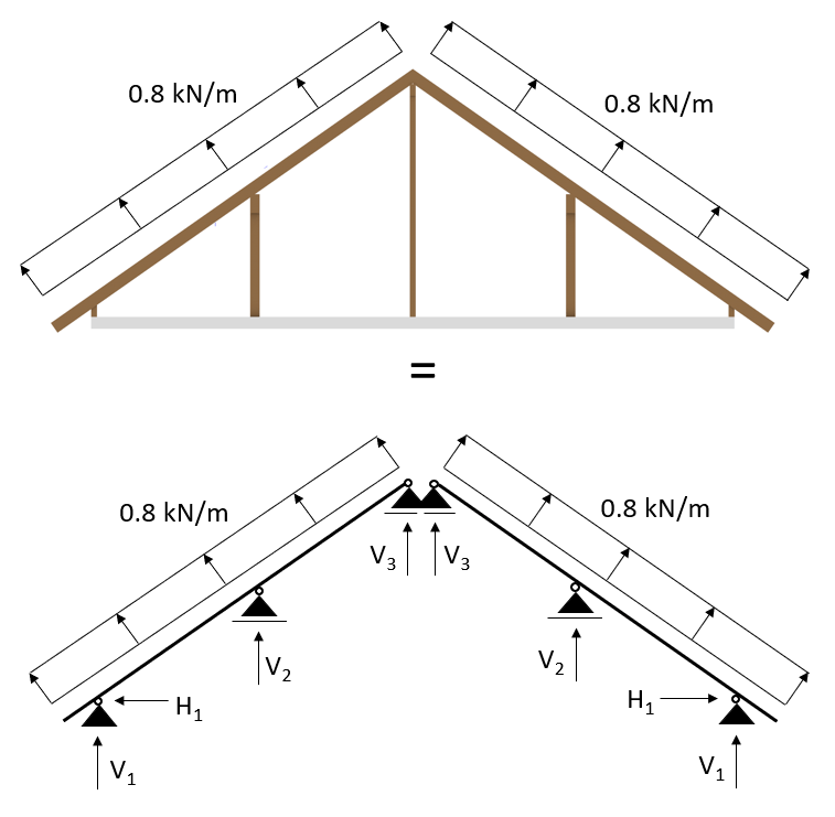
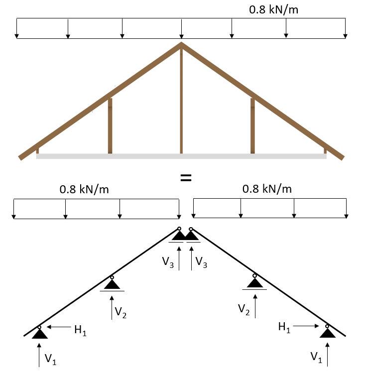
The live load on the roof is applied in the same way as the dead load. Z axis downwards while it is following the slope of the roof for its distribution.
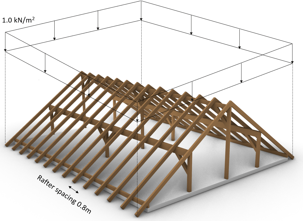
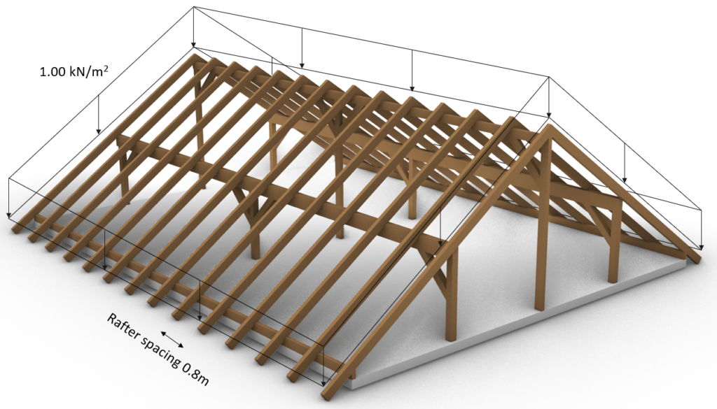
Live load in 3D system
In this example, we use 1.0 kN/m2 as characteristic live load on the roof. This value can be looked up in the Eurocode National Annex and differs from country to country.
Live load in 2D system
$$1.0 \frac{kN}{m^2} * 0.8 m = 0.8 \frac{kN}{m^2} $$
And this line load can be applied in a 2D system:
5. Seismic load
💡
The seismic load is the resulting force due to earthquakes.
Unfortunately, I do not know exactly how you apply seismic loads to roofs because I have so far only lived in regions that had minimal or no seismic activity, where the leading lateral force has always been wind.
But here is a good YouTube video that explains the seismic loads very well.
Conclusion
Now, that you got an understanding of what loads act on roofs and how to apply them, it’s time to understand how to calculate the loads
Because there are always multiple loads acting on a structural element. Considering these different loads in the structural design is done by setting up Load Combinations with safety factors.
Once all load cases and combinations are set up, the structural elements can be designed.
If have written a very detailed book about the structural design of residential timber roofs. You can read more about that book here.
If you don’t want to miss any new structural design tutorials, then subscribe to our free weekly newsletter.
Or subscribe to my YouTube channel for regular updates.
Let’s design better structures together,
Laurin.

Laurin Ernst
Roof Loads FAQ
– Dead load
– Wind load
– Snow load
– Live load
– Seismic load
Roof loads are calculated from formulas given in Standards. Roof loads in Europe – for example – are calculated according to Eurocode. Every load (snow, wind, dead, live & seismic) is calculated according to its specific Standard. Every country in Europe has furthermore its own National Annex which specifies parameters.
![Uniformly Distributed Load [All YOU Need To Know]](https://www.structuralbasics.com/wp-content/uploads/2023/04/Uniformly-distributed-loads-768x439.jpg)
![Rafter Roof Design [Step-By-Step Guide]](https://www.structuralbasics.com/wp-content/uploads/2022/04/Rafter-Roof-Design-1-768x439.jpg)
![Vertical Load Transfer In Structural Engineering [2026]](https://www.structuralbasics.com/wp-content/uploads/2024/09/Vertical-load-transfer-1-768x439.jpg)

This really answered my downside, thanks!
Hi,
glad to hear that the content helps!
Cheers,
Laurin
Usually adopted roof loads as below for pitched foof above 15 degree slope.
dead load
Imposed load
Wind load
Seismic load that are transferable to main structure for dedign
Hi,
Yes that’s right. In some countries however, the seismic load is not critical and it can therefore be argued for not to verify for the seismic load.
Cheers,
Laurin