Timber Purlin roof design – Complete guide
After we have designed the rafters of the purlin roof in the last article, we are now applying the support forces of the rafters to the purlins and design those elements….
Sounds exciting, right?🔥
Let’s get into it👍.
To be on the same page, we should firstly describe what a purlin roof is, and what are the purlins of it? 🤔
💡
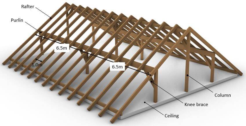
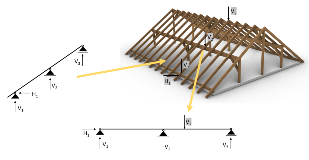
Statically speaking, the purlin roof exists of multiple statical systems. The loads are first taken by the sheeting and transferred to the rafters. The support forces of the rafters are taken by the purlins. The purlins are horizontal beams which transfer the loads to either walls or columns.
I know all this sounds quite complicated, but don’t worry, we will explain it practically with examples and pictures.
Let me explain to you the steps we have to do to dimension a rafter. Let’s have a look at the steps we need to follow.
- Choose a right statical system, continuous beam in our case
- Calculate all characteristic loads (dead, snow, wind, live load, etc.)
- Calculate all load combinations
- Choose a timber material and find material properties ($k_{mod}$, $f_{c.0.k}$, $f_{m.k}$, $\gamma_{M}$)
- Assume the width w and height h of the cross section
- Verify the beam for bending. If not verified increase the width or height of the beam and do the calculation again
- Verify the beam for shear. If not verified increase the width or height of the beam and do the calculation again
- Verify the beam for the instantaneous deflection criteria. If not verified increase the width or height of the beam and do the calculation again
- Verify the beam for the final deflection criteria. If not verified increase the width or height of the beam and do the calculation again
- If all of those checks are now verified, then you have figured out the correct dimensions of the beam
Statical system
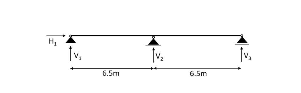
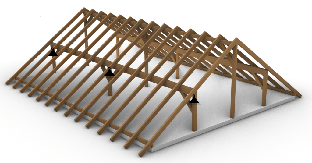
In general the statical system of the purlin is a beam. Depending on how many support it has either a simply supported or a continous beam. In our case we have a continuous beam with 3 supports.
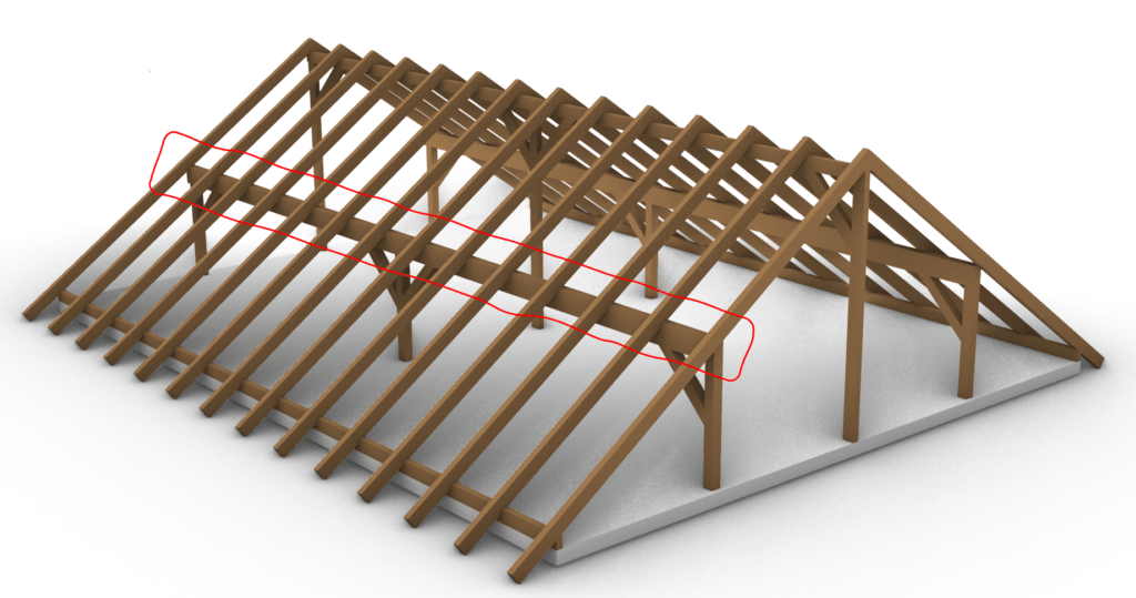
To not loose the connection to the overall roof when we are talking about the purlin beam we mean the red marked element of the timber roof.
.. and the supports (roller and pin) are the columns.
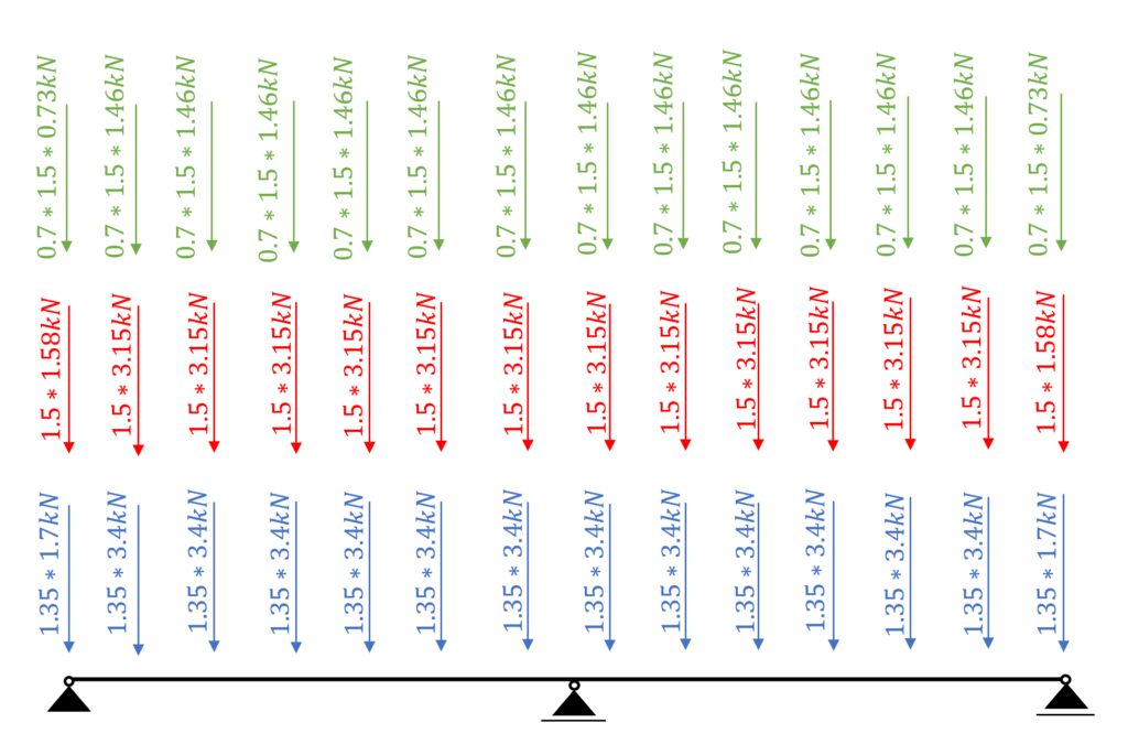
As we promised in the last article the support forces of the rafters are applied as point loads on the purlin roof – in the opposite direction!
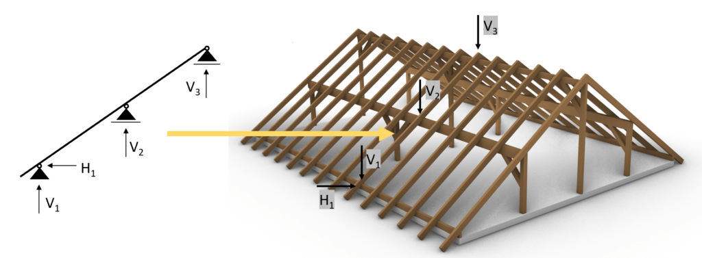
Therefore we need to calculate the support forces of the rafters due to the characteristic loads. Another way is to calculate the biggest design support loads (from load combinations). We are choosing the first way.
Loads
The characteristic loads will not be derived in this article. We explained the calculation of dead, live, wind and snow loads for pitched roofs thoroughly in previous articles.
❗
Loads depend on a lot of different factors like location, National Annex and geometry of the building and roof to name just a few. Loads therefore need to be calculated for every structure.
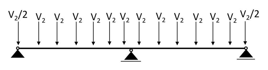
As already mentioned we are interested in the characteristic support forces of the rafters which we then apply to the purlin.
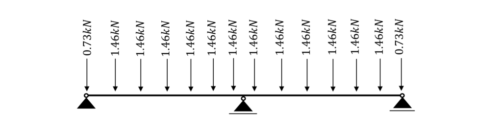
And for 14 rafters we get 14 point loads 😁
Let’s do an example. We will apply the characteristic snowload to the rafter to see what pointload needs to get applied to the purlins.
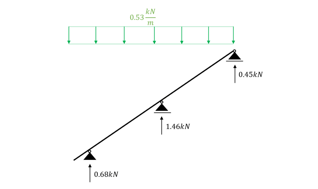
.. When designing the “middle” purlin, we can now apply 1.46 kN to the purlin beam as the characteristic snow load.
It is like applying the characteristic snow line load to the roof rafter.
Now we do this for all the characteristic loads we have. To speed things a bit up we are only considering the worst-case wind load value.
3D FE programmes can take all the different values into account. This would be too much data in our “simple” tutorial.
| $s_{k}$ | 1.46 kN | Characteristic value of snow load |
| $g_{k}$ | 3.40 kN | Characteristic value of dead load |
| $q_{k}$ | 3.15 kN | Characteristic value of live load |
| $w_{k}$ | 0.72 kN | Characteristic value of wind load (Area H) |
The self-weight of the purlin has to be added to $g_{k}$ as well.
When you design an element like the purlin, you do not know the exact dimensions of the cross-section. Therefore, you assume the width and height.
Once the correct cross-section is found, the self-weight gets updated as well.
However, we will not do this in this tutorial because it makes things more complicated and the focus of this tutorial is on the design of the timber elements.
Load combinations
Luckily we have already written an extensive article about what load combinations are and how we use them. In case you need to brush up on it you can read the blog post here.
❗We are choosing to include $w_{k.H.}$ = 0.72 kN as the wind load in the load combinations and the following calculations to keep it clean.
In principle, you should consider all load combinations. However, with a bit more experience, you might be able to exclude some of the values.
In modern FE programs, multiple values for the wind load can be applied, and load combinations automatically generated.
So the computer is helping us a lot. Just keep in mind that you should include all wind loads, but because of simplicity we do only consider 1 value in this article😁.
ULS Load combinations
| LC1 | $1.35 * 3.4 kN $ |
| LC2 | $1.35 * 3.4 kN + 1.5 * 3.15 kN$ |
| LC3 | $1.35 * 3.4 kN + 1.5 * 3.15 kN + 0.7 * 1.5 * 1.46 kN$ |
| LC4 | $1.35 * 3.4 kN + 0 * 1.5 * 3.15 kN + 1.5 * 1.46 kN$ |
| LC5 | $1.35 * 3.4 kN + 1.5 * 3.15 kN + 0.7 * 1.5 * 1.46 kN + 0.6 * 1.5 * 0.72 kN $ |
| LC6 | $1.35 * 3.4 kN + 0 * 1.5 * 3.15 kN + 1.5 * 1.46 kN + 0.6 * 1.5 * 0.72 kN $ |
| LC7 | $1.35 * 3.4 kN + 0 * 1.5 * 3.15 kN + 0.7 * 1.5 * 1.46 kN + 1.5 * 0.72 kN $ |
| LC8 | $1.35 * 3.4 kN + 1.5 * 1.46 kN $ |
| LC9 | $1.35 * 3.4 kN + 1.5 * 0.72 kN $ |
| LC10 | $1.35 * 3.4 kN + 1.5 * 3.15 kN + 0.6 * 1.5 * 0.72 kN $ |
| LC11 | $1.35 * 3.4 kN + 1.5 * 0.72 kN + 0.7 * 1.5 * 1.46 kN $ |
| LC12 | $1.35 * 3.4 kN + 1.5 * 1.46 kN + 0.6 * 1.5 * 0.72 kN$ |
Characteristic SLS Load combinations
| LC1 | $3.4 kN $ |
| LC2 | $3.4 kN + 3.15 kN$ |
| LC3 | $3.4 kN + 3.15 kN + 0.7 * 1.46 kN$ |
| LC4 | $3.4 kN + 3.15 kN + 0.6 * 0.72 kN$ |
| LC5 | $3.4 kN + 3.15 kN + 0.7 * 1.46 kN + 0.6 * 0.72 kN $ |
| LC6 | $3.4 kN + 0 * 3.15 kN + 1.46 kN + 0.6 * 0.72 kN $ |
| LC7 | $3.4 kN + 0 * 3.15 kN + 0.7 * 1.46 kN + 0.72 kN $ |
| LC8 | $3.4 kN + 1.46 kN$ |
| LC9 | $3.4 kN + 0.72 kN $ |
| LC10 | $3.4 kN + 3.15 kN + 0.6 * 0.72 kN $ |
| LC11 | $3.4 kN + 0.72 kN + 0.7 * 1.46 kN $ |
| LC12 | $3.4 kN + 0 * 3.15 kN + 1.46 kN$ |
| LC13 | $3.4 kN + 0 * 3.15 kN + 0.72 kN$ |
✔️
Line loads…
Since the distance between the rafters is set to 1.0 m the line loads have the same values as the area loads. If the spacing (distance between rafters) was 0.8 m then all Area loads would have needed to be multiplied by 0.8 m.
Rafter timber material
For this blog post/tutorial, we are choosing a Glulam GL 30h. More comments on which timber material to pick and where to get the properties from were made here.
The following characteristic strength and stiffness parameters were found online from a manufacturer.
| Bending strength $f_{m.k}$ | 30 $\frac{N}{mm^2}$ |
| Tension strength parallel to grain $f_{t.0.k}$ | 24 $\frac{N}{mm^2}$ |
| Tension strength perpendicular to grain $f_{t.90.k}$ | 0.5 $\frac{N}{mm^2}$ |
| Compression strength parallel to grain $f_{c.0.k}$ | 30 $\frac{N}{mm^2}$ |
| Compression strength perpendicular to grain $f_{c.90.k}$ | 2.5 $\frac{N}{mm^2}$ |
| Shear strength $f_{v.k}$ | 3.5 $\frac{N}{mm^2}$ |
| E-modulus $E_{0.mean}$ | 13.6 $\frac{kN}{mm^2}$ |
Modification factor $k_{mod}$
If you do not know what the modification factor $k_{mod}$ is, we wrote an explanation to it in a previous article, which you can check out.
Since we want to keep everything as short as possible, we are not going to repeat it in this article – we are only defining the values of $k_{mod}$.
For a residential house which is classified as Service class 1 according to EN 1995-1-1 2.3.1.3 we extract the following load durations for the different loads.
| Self-weight/dead load | Permanent |
| Live load, Snow load | Medium-term |
| Wind load | Instantaneous |
❗
The snow load can also be categorized as a short-term load. This depends on the location and the National Annex.
From EN 1995-1-1 Table 3.1 we get the $k_{mod} values for the load durations and a Glulam GL 30h (Glued laminated timber).
| $k_{mod}$ | |||
|---|---|---|---|
| Self-weight/dead load | Permanent action | Service class 1 | 0.6 |
| Live load, Snow load | Medium term action | Service class 1 | 0.8 |
| Wind load | Instantaneous action | Service class 1 | 1.1 |
Partial factor $\gamma_{M}$
According to EN 1995-1-1 Table 2.3 the partial factor $\gamma_{M}$ is defined as
$\gamma_{M} = 1.3$
❗
Please be aware that those factors can vary from country to country. So please make sure to check those values with your National Annex.
Assumption of width and height of rafter
We are defining the width w and height h of the C24 structural wood Cross-section as
Width w = 200 mm
Height h = 320 mm
Those values are based on the experience of the designer.
💡We highly recommend doing any calculation in a program where you can always update values and not by hand on a piece of paper!
I made that mistake in my bachelor. In any course and even in my bachelor thesis, I calculated everything except the forces (FE program) on a piece of paper.
Now that we know the width and the height of the Cross-section we can calculate the Moment of inertias $I_{y}$ and $I_{z}$.
$I_{y} = \frac{w * h^3}{12} = \frac{200mm * (320mm)^3}{12} = 5.46 * 10^8 mm^4 $
$I_{z} = \frac{w^3 * h}{12} = \frac{(200mm)^3 * 320mm}{12} = 2.13 * 10^8 mm^4 $
ULS Design
In the ULS (ultimate limit state) Design we verify the stresses in the timber members due to bending and shear.
In order to calculate the stresses of our purlins, we need to calculate the Bending Moments and shear forces due to different loads.
This is a little bit more work than for a flat roof/beam (simply supported) because our statical system has 3 supports (statically indeterminate) and we are having point loads.
Calculation of bending moment and shear forces
We use a FE program to calculate the bending moments and shear forces.
Load combination 5 with live load as leading, snow and wind load as reduced load leads to the highest results however due to different $k_{mod}$ values for LC5 (instantaneous) and LC3 (medium), LC3 will lead to the highest utilization $\eta$.
Load combination 3
❗
Because of the $k_{mod}$ factor, the biggest loads might not lead to the worst case scenario. Be careful here.
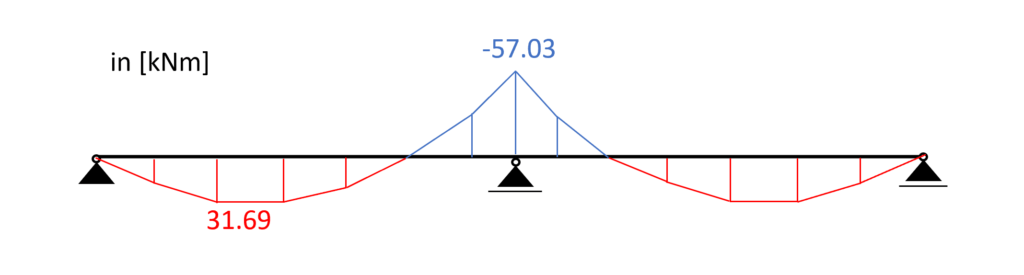
Load combination 3 – Bending moments
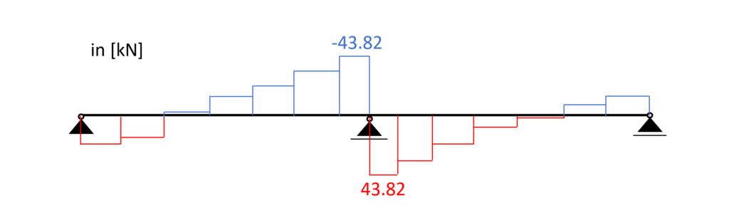
Load combination 3 – Shear forces
Bending
From the max. bending moment (midsupport: -57.03 kNm) we can calculate the stress in the most critical cross section.
Bending stress:
$\sigma_{m} = \frac{M_{d}}{I_{y}} * \frac{h}{2} = \frac{57.03 kNm}{5.46*10^{-4}m^4} * \frac{0.32m}{2} = 16.7 MPa$
Resistance stresses of the timber material:
$ f_{d} = k_{mod} * \frac{f_{k}}{\gamma_{m}} $
| LC3 (M-action) | $k_{mod.M} * \frac{f_{m.k}}{\gamma_{m}} $ | $0.8 * \frac{30 MPa}{1.3} $ | $18.46 MPa $ |
Utilization according to EN 1995-1-1 (6.19)
$\eta = \frac{\sigma_{m}}{f_{m.d}} = 0.905 < 1.0$
✔️
Bending is therefore verified.
Shear
From the max. shear force (midsupport: 43.82 kN) we can calculate the shear stress in the most critical cross section.
Shear stress:
$\tau_{d} = \frac{3*V}{2*w*h} = \frac{3*43.82 kN}{2*0.2m*0.32m} = 1.03 MPa$
Resistance stresses of the timber material:
$ f_{v} = k_{mod.M} * \frac{f_{v}}{\gamma_{m}} $
$ f_{v} = 0.8 * \frac{3.5 MPa}{1.3} = 2.15 MPa$
Utilization according to EN 1995-1-1 (6.13)
$\eta = \frac{\tau_{v}}{f_{v}} = 0.477 < 1.0$
✔️
Shear is therefore verified.
SLS Design
We also discussed the SLS design a bit more in detail in a previous article. In this blog post we are not explaining too much but rather show the calculations😊.
Instantaneous deformation $u_{inst}$
$u_{inst}$ (instantaneous deformation) of our beam can be calculated with the load of the characteristic load combination.
As for the bending moments, shear and axial forces, we are using a FE programme to calculate the deflections due to our Load combinations.
LC 5 of the characteristic SLS load combinations leads to the largest deflection u.
$u_{inst}$ = 11.7 mm
Unfortunately, EN 1995-1-1 Table 7.2 recommends values for $w_{inst} only for “Beams on two supports” and “Cantilevering beams” and not for a continuous beam, which is our case.
However, the limits of the deflection can be agreed upon with the client and the structure is not collapsing due to too large deflections if the rafter is verified for all ULS calculations.
So for the sake of this tutorial we are using the value for “Beam on two supports” from EN 1995-1-1 Table 7.2.
$w_{inst}$ = l/300 = 6.5m/300 = 21.7 mm
Utilization
$\eta = \frac{u_{inst}}{w_{inst}} = \frac{11.7mm}{21.7mm} = 0.54$
✔️
The Instantaneous deflection is verified for the purlin.
Final deformation $u_{fin}$
$u_{fin}$ (final deformation) of our beam can be calculated by adding the creep deformation $u_{creep}$ to the instantaneous deflection $u_{inst}$.
Therefore, we will calculate the creep deflection with a FE program.
This might be a bit quick, but we have already covered the basics in the article about the timber beam dimensioning.
So check that out if you want to know exactly how to calculate $u_{creep}$ by hand.
$u_{creep}$ = 3.36mm
Adding the creep to the instantaneous deflection leads to the final deflection.
$u_{fin} = u_{inst} + u_{creep} = 11.7mm + 3.36mm= 15.06mm$
Limit of $u_{fin}$ according to EN 1995-1-1 Table 7.2
$w_{fin}$ = l/150 = 6.5m/150 = 43.3 mm
Utilization
$\eta = \frac{u_{fin}}{w_{fin}} = \frac{15.06mm}{43.3mm} = 0.35$
✔️
The final deflection is verified for the purlin.
🎉 Finishing off with the final deflection criteria, the purlin is now designed and verified.
The next step is to apply the support forces to the columns or walls – depending on how the design looks like – and design the columns. So see you in the next tutorial😎.
![Rafter Roof Design [Step-By-Step Guide]](https://www.structuralbasics.com/wp-content/uploads/2022/04/Rafter-Roof-Design-1-768x439.jpg)