Masonry Wall Subjected To Point Load [Step-By-Step Guide]
Masonry walls are commonly used in residential family houses. They resist vertical and horizontal loads from floors or external wind. And in some cases, masonry walls need to resist concentrated loads from beams.
In this guide, I’ll show, step-by-step, how you verify masonry walls that are subjected to point loads.
Let’s get started. 🚀🚀
Process of Verifying Masonry Walls for Concentrated Loads
Before we dive into the nerdy calculations, it’s good to get an overview of the steps that need to be taken in the design. These are the steps, I always follow when I verify point loads on masonry walls in my job as a structural engineer. 👇👇
- Calculate characteristic load that act on the wall/beam
- Load combinations to find the design load
- Define geometry
- Material properties of the wall
- ULS verification of masonry wall subjected to concentrated load
There are many different types of masonry. In this tutorial, we’ll use autoclaved aerated concrete units, which are classified as Group 1 according to EN 1996-1-1 3.1.1 (4).
To be more specific, we’ll use the product ThermSuper wall element from Ytong.
1. Characteristic Loads
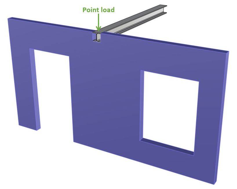
The masonry wall supports a steel beam. This beam on the other hand is the support of another structure such as a roof or a floor which is exposed to loads such as snow, dead and live load.
These loads are taken up by the steel beam and transferred to the masonry wall and the other element that supports the beam. The masonry wall transfers then the loads further to the foundation. Finally, the loads are taken up by the soil.
In this tutorial, we won’t explain how loads travel through a building/structure. Instead, we’ll define some point loads that correspond to the reaction forces of the steel beam and the concentrated load that is exposed to the wall.
The following characteristic load values are assumptions.
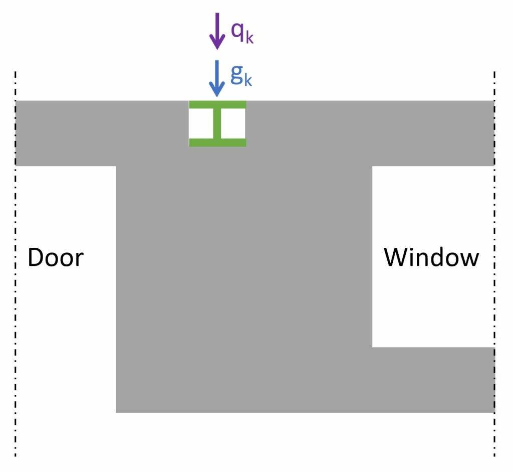
| gk | 20 kN | Characteristic dead load |
| qk | 12 kN | Characteristic live load |
❗❗
The characteristic values of loads depend on a lot of different factors like location, National Annex and geometry of the building and roof to name just a few. Loads therefore need to be calculated for every structure.
Check out our articles about the dead load and the live load.
2. Load Combinations
Load combinations combine several load cases and multiply the characteristic loads with safety factors.
Luckily, we have already written an extensive article about what load combinations are and how we use them.
In case you need to brush up on it or want to check how we derived the safety factors, you can read the blog post here.
ULS load combinations
| LC1 | $1.35 \cdot g_{k} + 1.5 \cdot q_k$ | NEd = 32.3 kN |
3. Geometry Of The Walls
Here are the dimensions and parameters of the wall:
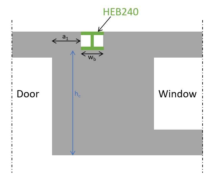
| Width of steel beam (HEB240) | wb = 240 mm |
| Distance from the end of the wall to the nearer edge of the loaded area | a1 = 0.5 m |
| Wall thickness | t = 100 mm |
| Height of the wall to the loaded area (HEB240) | hc = 3.8 m |
4. Masonry Properties
We’ll use autoclaved aerated concrete as the masonry type. To be more specific, we’ll use the wall element Ytong ThermSuper. You can check out its properties here.
| Characteristic compressive strength of masonry (Ytong datasheet) | $f_{k} = 1.8 MPa$ |
| Group (EN 1996-1-1 3.1.1 (4)) | 1 |
| Partial factor for compressive strength (Danish Annex) | $\gamma_{c.c} = 1.6$ |
| Design compressive strength of masonry | $f_d = \frac{f_k}{\gamma_{c.c}} = 1.13 MPa$ |
5. ULS Verification Of A Wall Subjected To A Concentrated Load
In this verification, we check that the compression stresses/forces due to the point load from the steel beam can be taken up by the masonry.
The resistance of the masonry is calculated according to EN 1996-1-1 (6.10):
$$N_{Rdc} = \beta \cdot A_b \cdot f_d$$
$\beta$ is an enhancement factor for concentrated loads and is calculated according to EN 1996-1-1 (6.11) with the following parameters:
| Loaded area | Ab = wb ⋅ t = 24000 mm2 |
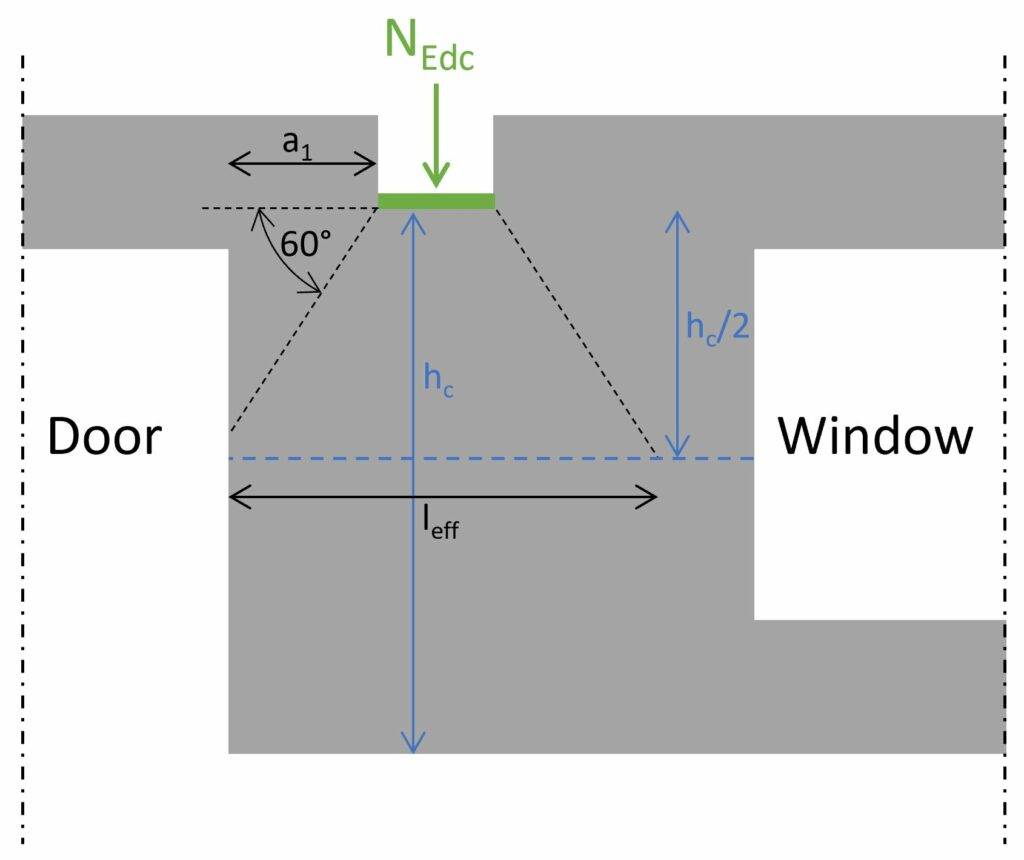
| Effective length of the bearing (determined at mid-height of the wall -> see image below (EN 1996-1-1 Figure 6.2)) | lefm = a1 + wb + hc/2 ⋅ tan(30°) = 1.84 m |
| Effective area of the bearing | Aef = lefm ⋅ t = 1.84 ⋅ 105 mm2 |
| Enhancement factor for concentrated loads (EN1996-1-1 (6.11)) | $\beta = (1 + 0.3 \cdot \frac{a_1}{h_c}) \cdot (1.5 – 1.1 \cdot \frac{A_b}{A_{ef}}) = 1.41$ |
| Check if $\beta$ > 1.0 (EN 1996-1-1 (6.11) | $\beta = max(\beta ; 1.0) = 1.41$ |
| Check minimum value of $\beta$ (EN 1996-1-1 (6.11) | $\beta = min(\beta; 1.5; 1.25 + \frac{a_1}{2 \cdot h_c}) = 1.32$ |
❗❗
Note that this formula for $\beta$ is only used for masonry units in group 1. $\beta$ = 1.0 for groups 2, 3 and 4 according to EN 1996-1-1 6.1.3 (3).
Now, we can calculate the resistance and verify the wall for the point load NEd.
| Resistance of wall for a concentrated load (EN 1996-1-1 (6.10)) | $N_{Rdc} = \beta \cdot A_b \cdot f_d = 35.53 kN$ |
| Utilisation | $\eta = \frac{N_{Ed}}{N_{Rdc}} = 0.91 < 1.0$ |
The wall subjected to a concentrated load is verified.
Conclusion
Et voilà, the masonry wall is verified for a concentrated point load. 💯💯
If you are new to structural design, then check out more of our design tutorials where you can learn how to design elements such as: 👇👇
- Design reinforced concrete beams
- Design of unreinforced masonry shear wall
- Punching shear design of a flat slab
But now, I would like to hear from you: Are you designing masonry walls for a new building? Or are you renovating your own house? Tell us a bit about the structure, as we all want to learn from each other. ✍️✍️

![Timber Beam Design [Step-By-Step]](https://www.structuralbasics.com/wp-content/uploads/2022/01/Wood-timber-beam-design-Bending-moment-shear-and-deformation-verification-kmod-strength-768x439.png)