Structural Frame Types And How They Work {2026 Guide}
Structural frames are a static system commonly used for structures like warehouses, sports halls, carports and bridges. They are characterized by resisting horizontal loads without the need for bracing elements or shear walls.
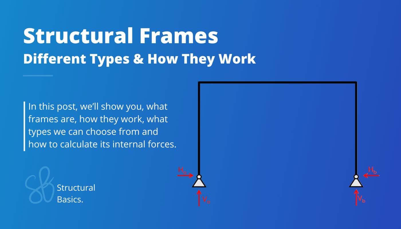
In this guide, I’ll show, what frames are, which types we use in structural engineering and how to calculate its internal forces.
Let’s get started. 🚀🚀
What Is A Frame?
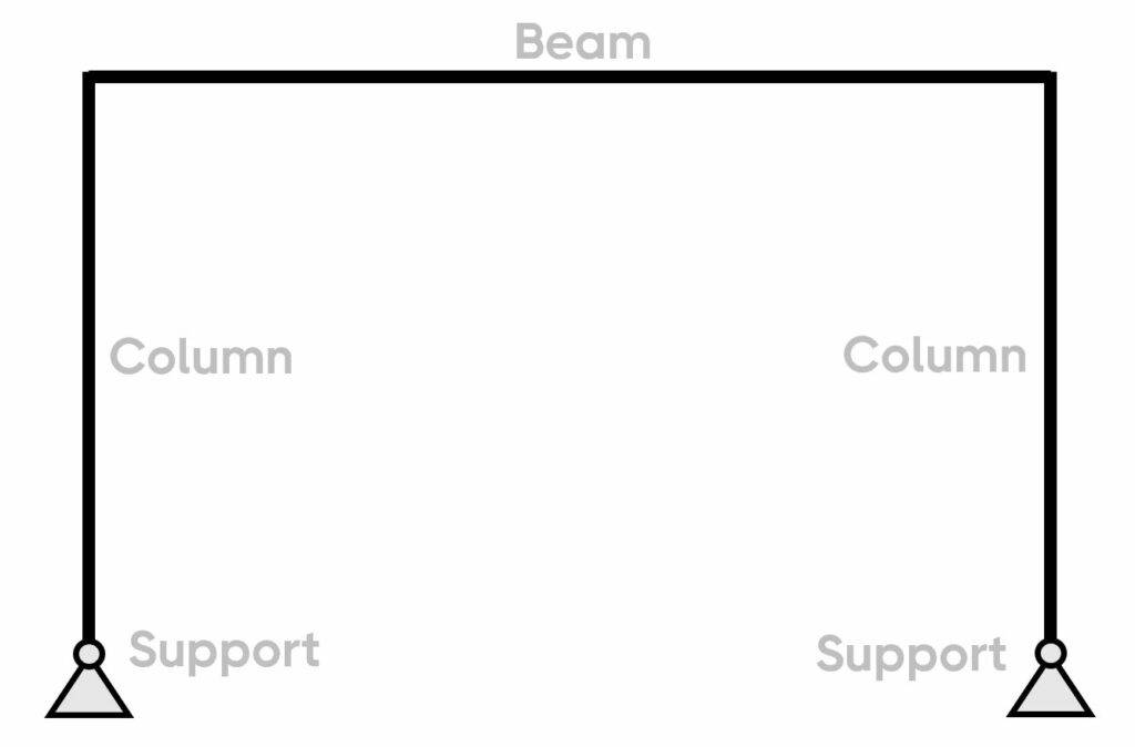
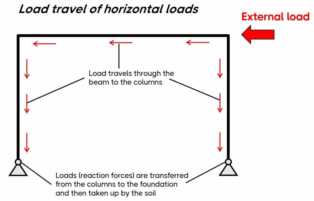
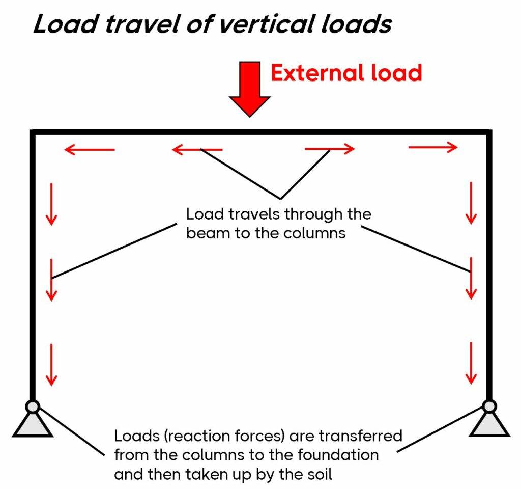
A frame is a static and structural system that consists of beams and columns. The main characteristic of a frame is that it’s a stable structure without depending on floors and walls (in-plane). In the next picture, you can see that the horizontal loads travel through the frame and to the foundation.
Frames are built in all 3 main materials – timber, steel and reinforced concrete. The static system of the frame can have different support and connection conditions, which are explained further in the following.
The Static System of a Frame
The frame structure has a variety of different static systems due to different support and connection conditions.
Here are the most common static systems you can choose from: 👇👇
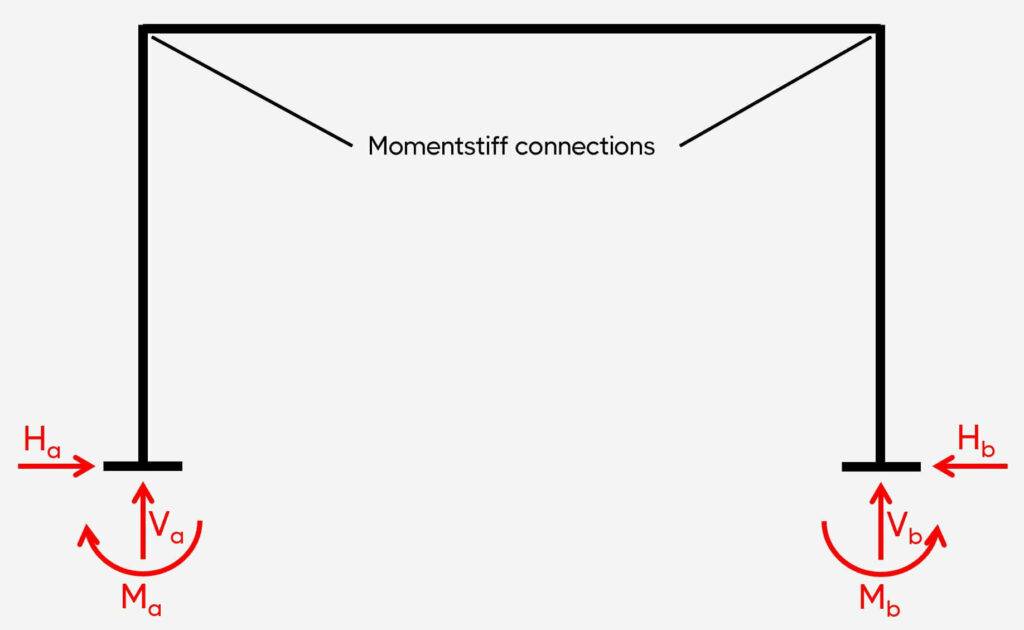
1. Rigid frame (fixed-fixed frame)
Support types
2 fixed supports
Reactions
Fixed: Vertical, horizontal & moment
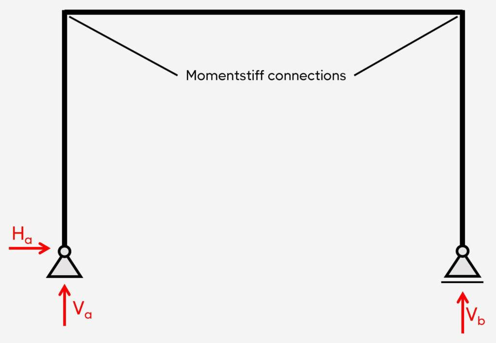
The rigid frame is categorized by having 2 fixed supports and momentstiff connections. Therefore, the static system is indeterminate. The fixed supports (a) and (b) take up
- a vertical reaction force V
- a horizontal reaction force H and
- a moment reaction M
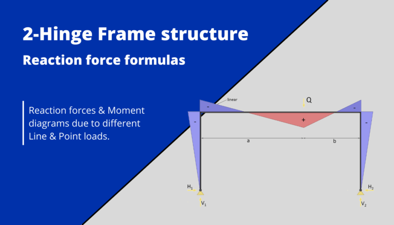
You can check out the internal force formulas of rigid frames here:
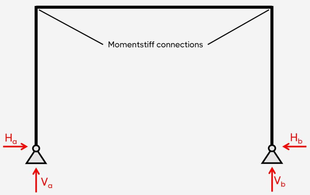
2. Pinned-pinned frame
Support types
2 pins
Reactions
Pin: Vertical & horizontal
The pinned-pinned frame is characterized by having 2 pin supports and momentstiff connections. This static system is also statically indeterminate.
The pinned supports (a) and (b) take up
- a vertical reaction force V
- a horizontal reaction force H and
3. Pinned-roller frame
Support types
2 pins
Reactions
Pin: Vertical & horizontal
The pinned-roller frame is characterized by having 1 pin support, 1 roller support, and momentstiff connections. This static system is also statically determinate.
The pinned support (a) takes up
- a vertical reaction force V
- a horizontal reaction force H and
The roller support (b) takes up
- a vertical reaction force V
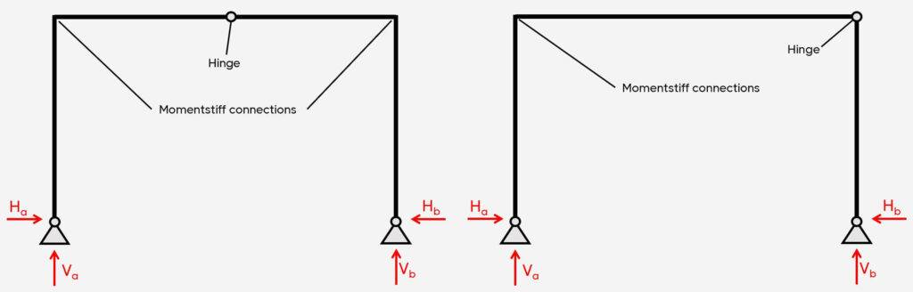
4. Frames with hinge connections
Support types
Fixed, pin and/or roller
Reactions
Pin: Vertical & horizontal
Roller: Vertical
Fixed: Vertical, horizontal & moment
💡💡 You can add 1 hinge connection to a pinned-pinned frame or 2 hinge connections to a fixed-fixed frame. But you can’t introduce a hinge to a pinned-roller frame because that would make the static system instable. 💡💡
Example Structures of Frames
Frames are commonly used in warehouses, parking garages, carports, industrial production facilities, sports halls to mention a few. Frames are even used for small span bridges (roughly 10 meter span).
They are lightweight and quick to construct.
The most common material that is used for frames is steel, but as mentioned earlier timber and concrete are also often used.
Let’s look at some more specific examples.
1. Warehouses
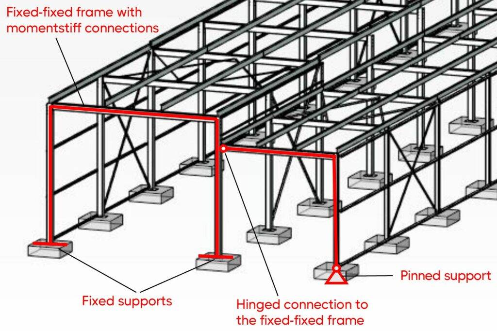
The steel warehouse from the picture below is the structure I designed for my bachelor thesis. 👇👇
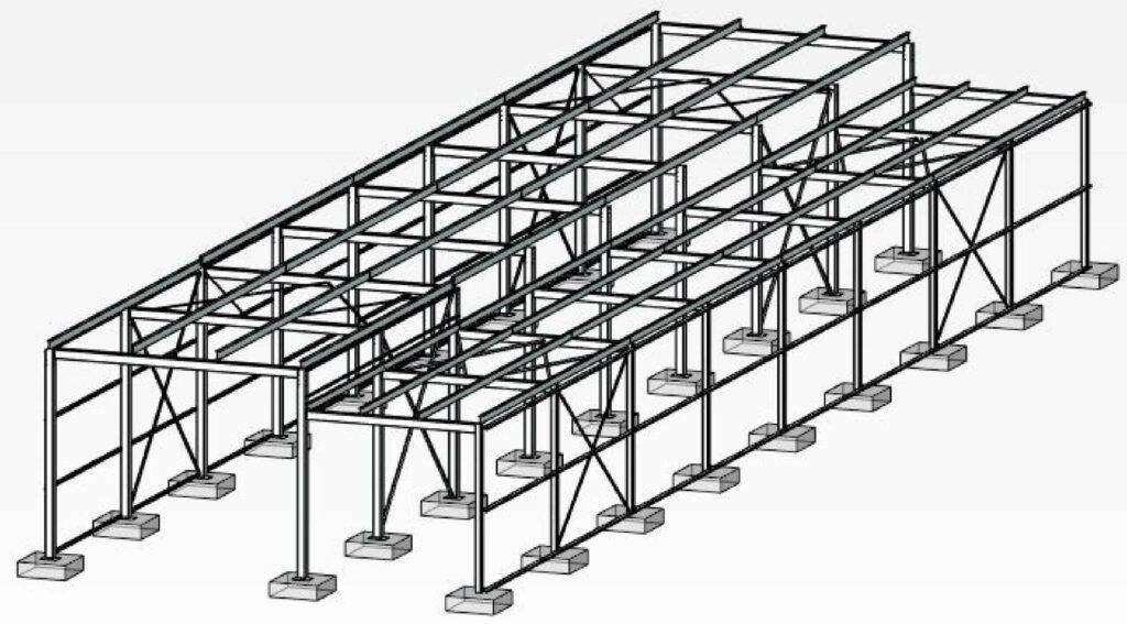
As the static system, I used a fixed-fixed frame and the frame extension (beam and column) were connected with a hinge to the column of the rigid frame.
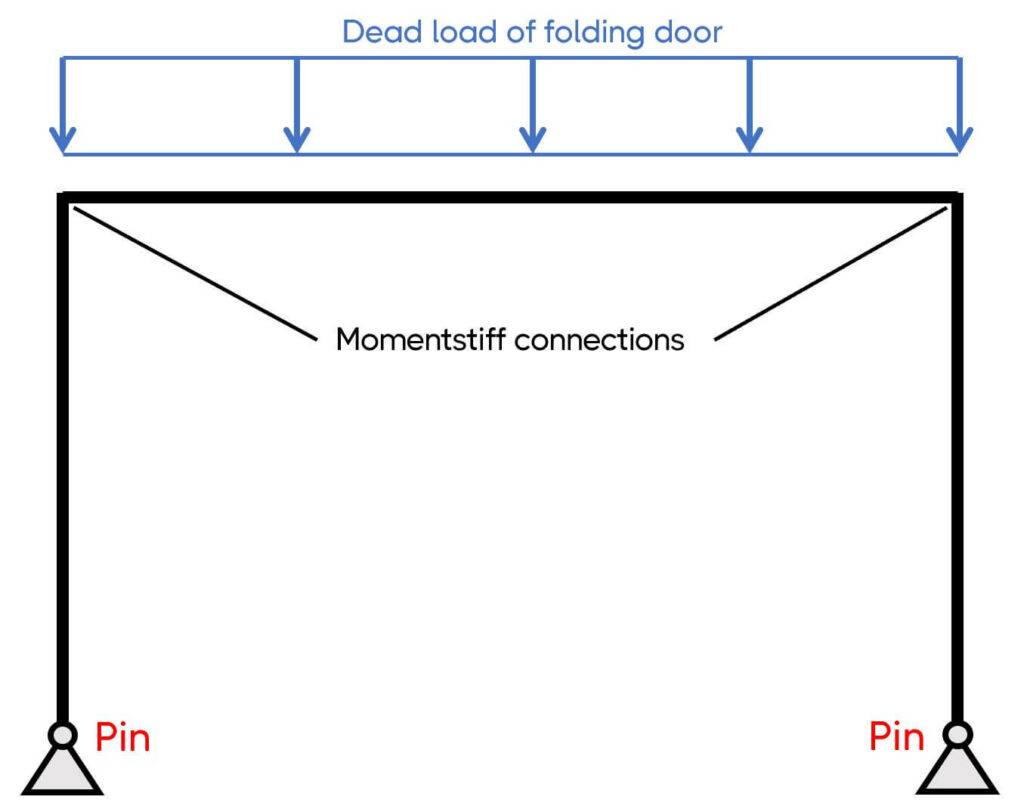
2. Timber frame as a support for a folding door
This is a structure I designed some time ago. The only purpose of the frame was to resist the vertical loads of the self-weight of a folding door inside an office building.
So, I choose the static system of a pinned-pinned frame with momentstiff connections in the corners.
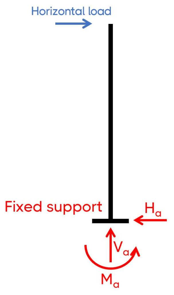
Now, I had one challenge with this frame: I couldn’t connect the frame to any of the existing structure, which meant that I had to make the frame also stable out-of-plane for potential horizontal loads like internal wind pressure or a person hitting the door.
So the support out-of-plane was designed as a fixed support. The frame out-of-plane was then a cantilever beam/column.
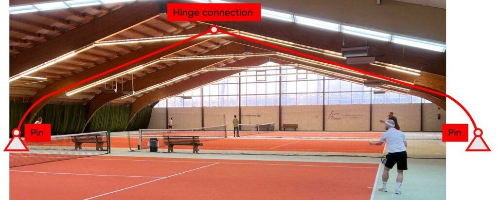
3. Timber frames in sports halls
Many sports halls are built with timber frames. In many cases tapered beams are used instead of straight ones to avoid moment stiff connections which are challenging to design and construct.
4. Frame bridge
Bridges with smaller spans are often frames. You can see an example → here ←.
The beam is the bridge deck and the columns are the abutment walls. I designed a bunch of these types of bridges in a earlier job as a BIM modeller. The amount of reinforcement that went into these structures was massive. It was very hard to read the reinforcement plans. Even for me, who created them. So we decided to also provide our 3D models to the construction companies.
Example Hand Calculation Of Internal Forces
Let’s define the dimensions and loading situation of the frame. 👇👇
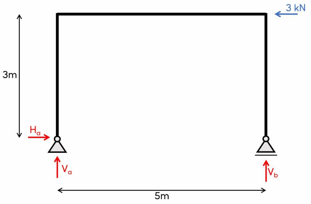
1. The first thing we always calculate for determinate structures are the reaction forces/moment. In our case, that is Va, Ha at support (a) and Vb at support (b) due to the equilibrium conditions.
Horizontal equilibrium:
$\sum H = 0: 3 kN – H_a = 0$
$H_a = 3 kN$
Now, to get the vertical reaction forces, we’ll take the moments in point (b):
$\sum M_b=0: V_a \cdot 5m – 3kN \cdot 3m = 0$
We now solve this equation for Va:
$V_a = \frac{3 kN \cdot 3m}{5m} = 1.8 kN$
We can now find Vb with the vertical equilibrium:
$\sum V = 0: V_a + V_b = 0$
$V_b = – V_a = -1.8 kN$
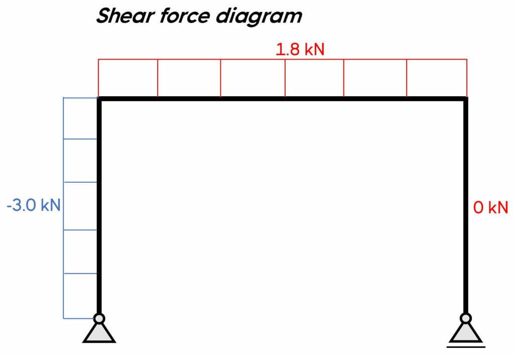
2. Calculation of the shear, normal and moment distribution along the frame due to the reaction forces and external load. The parameter x is introduced as the length between point a and any point on the left column.
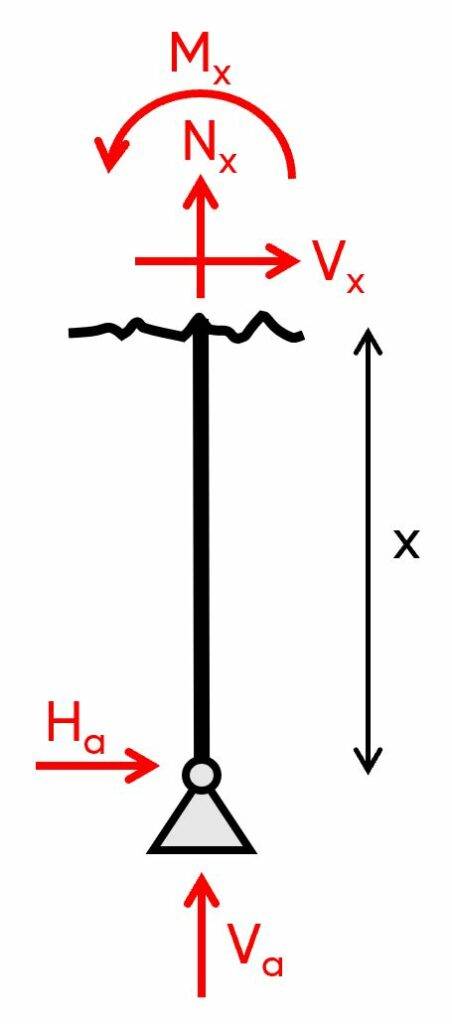
$\sum V = 0: V_a + N_x = 0 \rightarrow N_x = – 1.8 kN$
$\sum H = 0: H_a + V_x = 0 \rightarrow V_x = – 3 kN$
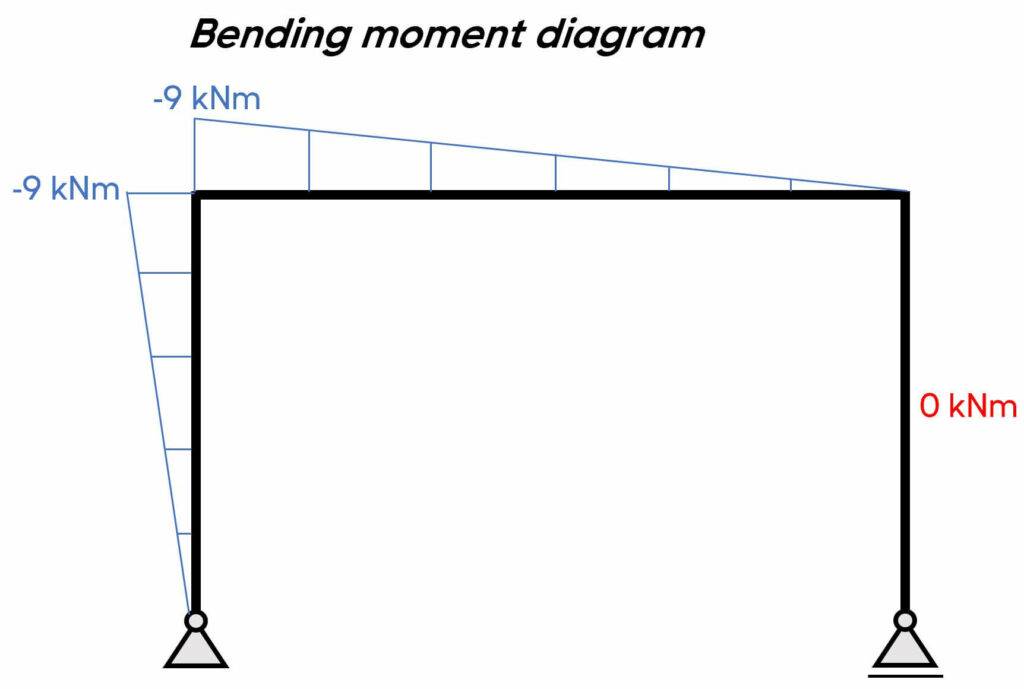
$\sum M_x = 0: M_x + H_a \cdot x = 0 \rightarrow M_x = – H_a \cdot x$
We can see from these results that the shear and normal forces in the left column are constant, but the bending moment is linear (increases/decreases with an increase of x).
Let’s set x = 3 m:
$M(x=3m) = – H_a \cdot 3m = – 9 kNm$
At the support M(x=0m) = 0 which makes sense when we have a pin support.
3. Calculation of the shear, normal and moment distribution along the beam.
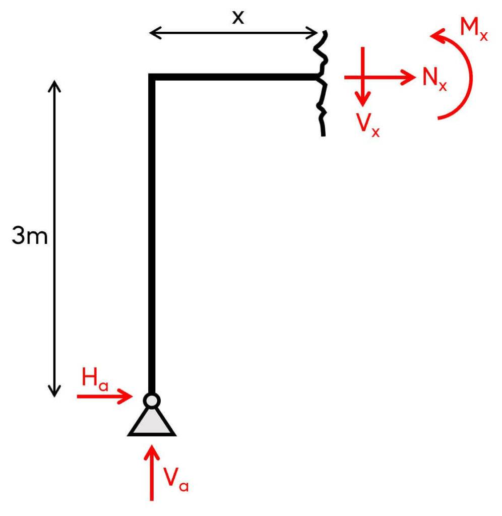
$\sum V = 0: V_a – V_x = 0 \rightarrow V_x = 1.8 kN$
$\sum H = 0: H_a + N_x = 0 \rightarrow N_x = – 3 kN$
$\sum M_x = 0: M_x + H_a \cdot 3m – V_a \cdot x = 0 \rightarrow M_x = V_a \cdot x – H_a \cdot 3m$
Let’s first set x=0m:
$M_x = V_a \cdot 0 – H_a \cdot 3m = – 9 kNm$
It’s the same value as for the column when we set x=3m.
And now, x=5m:
$M_x = V_a \cdot 5m – H_a \cdot 3m = 0 kNm$
With some experience, we already know that the bending moment in the right column is 0. Let’s run through the calculation anyways.
4. Calculation of the shear, normal and moment distribution along the right column.
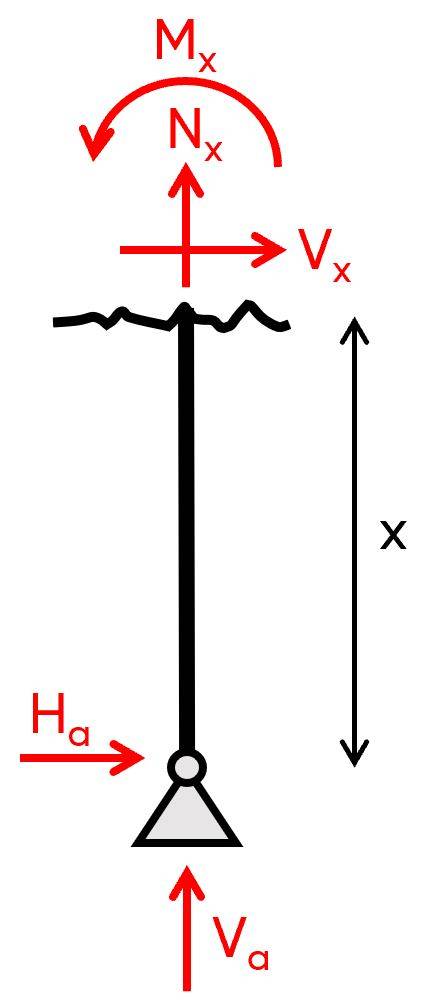
$\sum V = 0: V_b + N_x = 0 \rightarrow N_x = 1.8 kN$
$\sum H = 0: V_x = 0$
$\sum M_x = 0: M_x = 0$
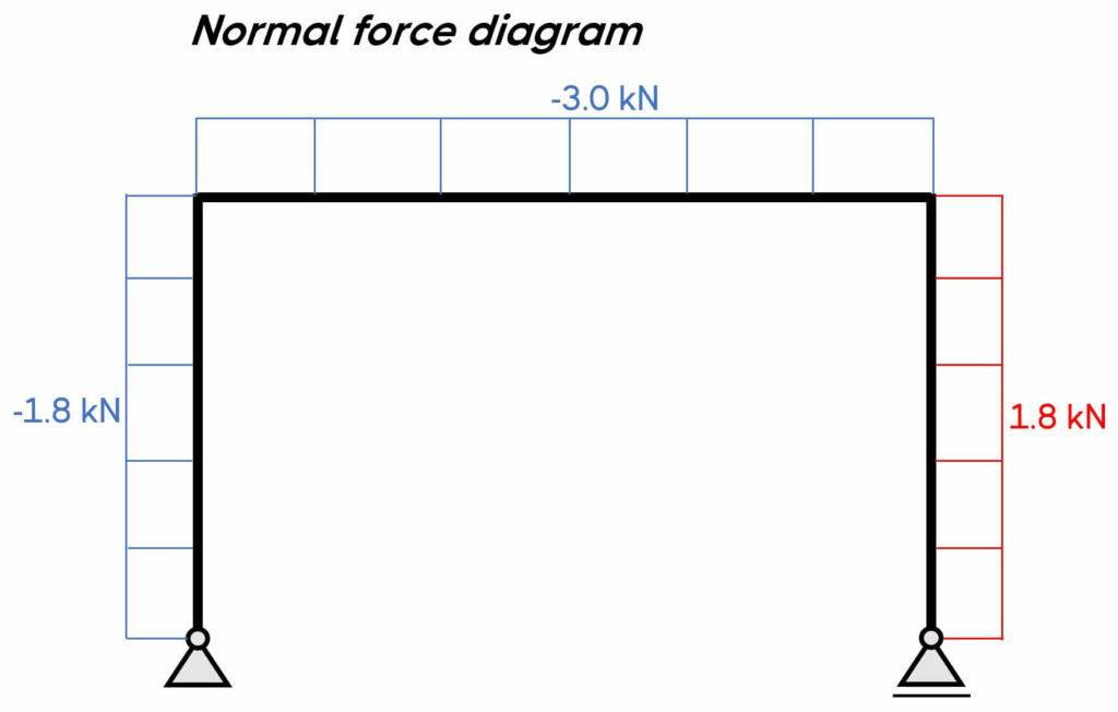
5. Bending moment, normal force and shear force diagrams.
We can plot the diagrams by hand.
Conclusion
Frames are a static system we use for many structures in structural engineering.
Hopefully, this gave you an overview and good understanding of how frames work and which types exist.
There are many other static systems that we use in our structural design. Check them out here: 👇👇
But now, I would like to hear from you: Are you designing a frame for a personal project? Or are you uni student confused about the different static systems? Let us know in the comments below.✍️