How To Find The Centroid [A Step-By-Step Guide]
Are you an engineer, student, or someone who is looking to understand how to find the centroid of a section? 🙋♂️🙋♂️
The centroid is a crucial parameter in determining the stability and strength of 3D objects such as beams, columns and slabs.
By understanding the centroid calculation, you are one step closer to designing the most complex engineering elements. 🔥🔥
In this beginner’s guide, we’ll walk you through the process of determining the centroid of a section step-by-step. 📄📄
Alright, let’s get started. 🚀🚀
What is The Centroid?
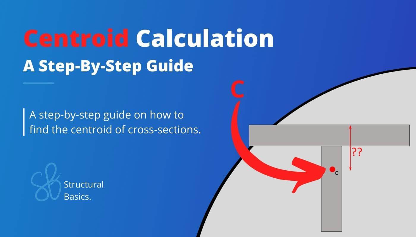
The centroid is a point of a cross-section or profile that represents the center of mass. It’s the point at which the entire area of the section can be assumed to be concentrated.
If a force is applied at that point, it will produce the same effect on the section as if the force were distributed uniformly across the entire area of the section.
The Centroid of a section is important for the calculation of the Moment of Inertia and Section Modulus of cross-sections. These are 2 important properties used in structural design of elements such as beams, columns and slabs.
In easy language, it’s a geometric property used in the design of flexural members.
Before we look at the calculation of the centroid, we have to clarify some concepts. 🧑🏫🧑🏫
The centroid is calculated by cross-sectional dimensions (height, width, etc.).
The following paragraphs are for everyone who doesn’t know what a cross-section is or how to determine it from 3D objects such as beams, columns, slabs and walls.
Everyone, who knows about cross-sections, can directly jump into the calculation section.⬇️⬇️
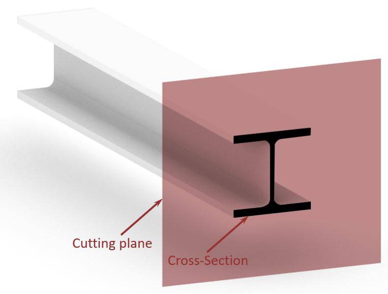
In structural engineering, cross-sections are determined by cutting through a 3D structural object, like a beam, column, slab, etc. perpendicular to its length. This is visualized in the following picture, where the cross-section of an I or H beam is shown.
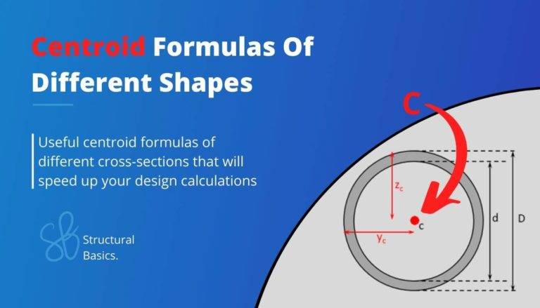
Here are some cheat sheets of formulas for the moment of inertia and section modulus of different sections and where the centroid was used:
Enough talk, let’s get into the calculations.🧮🧮
Calculation of The Centroid of A Section
There’s a simple step-by-step procedure that we can follow for any cross-section to calculate the centroid. 👍👍
Procedure:
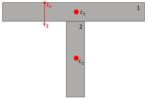
- Split the (Cross-) Section into its parts (see picture below). E.g. the T profile can be split into 2 parts, while the I-profile is split into 3 parts.
- Find the centroid of each part.
- With the centroid formula the centroid of the entire section (z-direction) is calculated:
$$z = \frac{\sum_{i=1}^{n} A_i \cdot z_i}{A}$$
With,
$A_i$ = area of a part i of the section
$z_i$ = vertical distance from reference point to the centroid of part i
$A$ = area of the section
OK, now let’s apply this procedure to the T Section. 👇👇
Example Calculation of A T Section
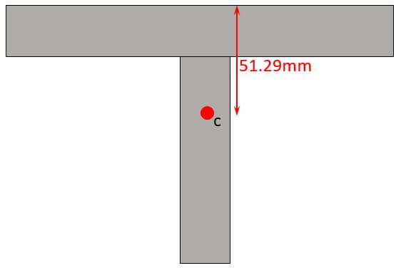
Let’s calculate the centroid for the following example T Section.
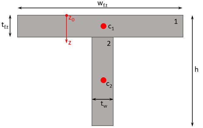
Now, let’s also define the dimensions needed:
$t_{f.t}$ = 15 mm
$h$ = 180 mm
$w_{f.t}$ = 200 mm
$t_w$ = 10 mm
As we see from the formula above, we need to calculate
- the area of each part i and
- the centroid of each part i
So let’s do that. ⬇️⬇️
Area of part 1
$$A_1 = t_{f.t} \cdot w_{f.t} = 15mm \cdot 200mm = 3000mm^2$$
Area of part 2
$$A_2 = t_{w} \cdot (h-t_{f.t}) = 10mm \cdot (180mm-15mm) = 1650mm^2$$
Centroid of part 1
$$z_{c.1} = \frac{t_{f.t}}{2} = \frac{15mm}{2} = 7.5mm$$
Centroid of part 2
$$z_{c.2} = t_{f.t} + \frac{h-t_{f.t}}{2} = 15mm + \frac{180mm – 15mm}{2} = 97.5mm$$
Alright, now let’s insert these results into the centroid formula
Centroid Formula
$$z = \frac{\sum_{i=1}^{n} A_i \cdot z_i}{A}$$
$$z = \frac{A_1 \cdot z_1 + A_2 \cdot z_2}{A_1 + A_2}$$
$$z = \frac{3000mm^2 \cdot 7.5mm + 1650mm^2 \cdot 97.5mm}{3000mm^2 + 1650mm^2}$$
$$z = 51.29mm$$
Centroid for Different Cross-Sections
We have already written a Cheat sheet with the Centroid Formulas for many different cross-sections around the strong and weak axis. Make sure to check that out, if you are looking for formulas.
The following cross-sections exist and find use in engineering:
- Rectangular section
- I or H section
- Circular section
- Hollow circular section
- Hollow rectangular section
- C Channel
- T Section
- L Section
- Composite Cross-section (concrete and steel, or concrete and timber)
Units of Measurement
As the centroid is often calculated as a distance from one of the section’s edges, mm [milimeter], cm [centimeter] or m [meter] is used.
Calculation of Centroid of Complex Cross-Sections
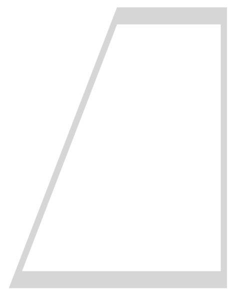
In engineering, you sometimes come across complex cross-sections, like in the picture below. In a university course, I had to calculate the moment of inertia of that section.
To do that, I needed the centroid first.
It was a beam used on the edge of a deck cross-section of a cable-stayed bridge.
To be honest with you – who likes to calculate the centroid of such a profile?
It’s time-consuming and prone to errors.❌❌
Luckily, there is a great tool that can help us to calculate the area.
It’s Rhinoceros/Grasshopper.
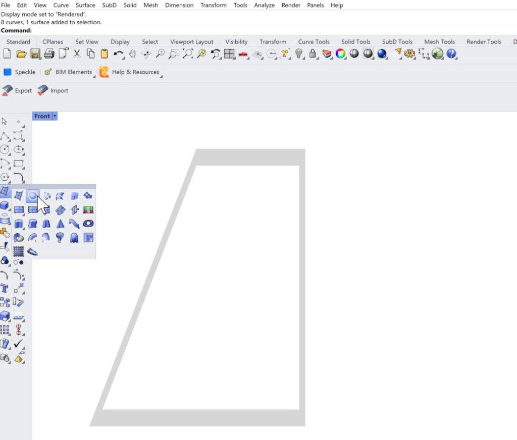
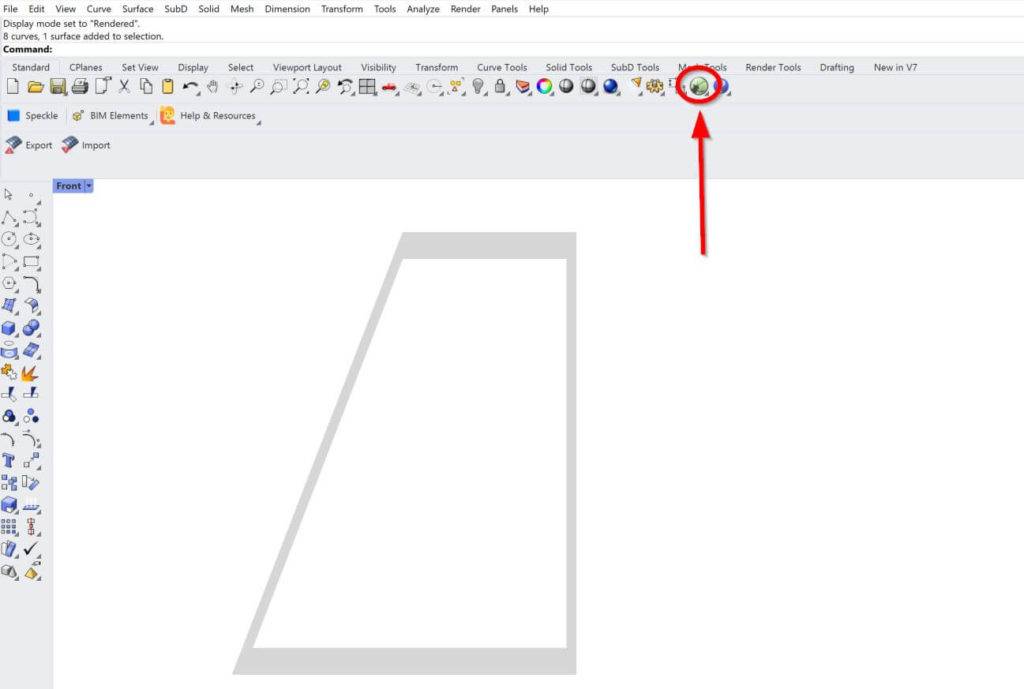
1. We simply draw the geometry in Rhinoceros and create a surface from lines.
2. We then open Grasshopper.
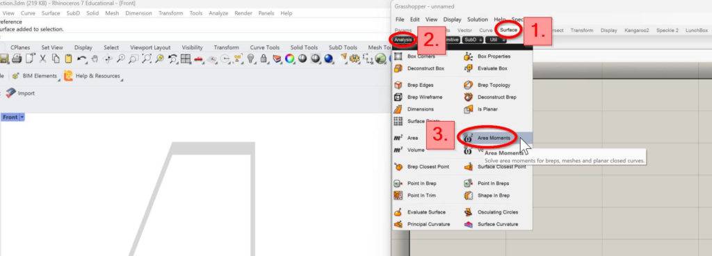
3. In Grasshopper, we click on Surface, Analysis and Area Moments.
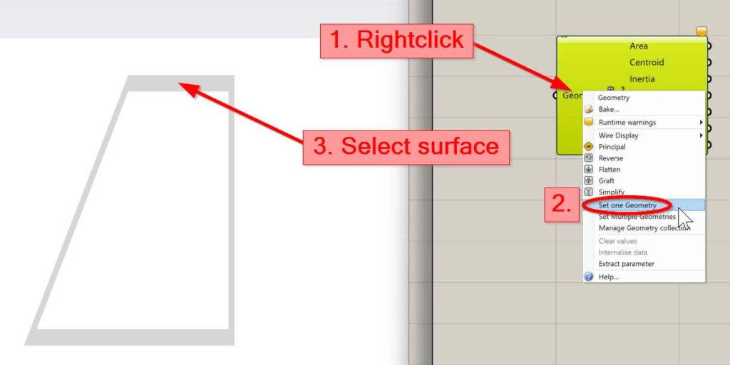
4. Right click on Geometry of the component, click on Set one Geometry and select the surface of the Cross-section.
5. Right click on Centroid and click on Bake
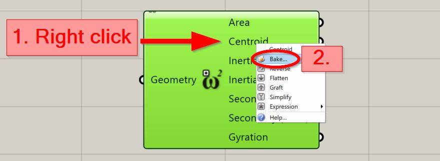
Now, the centroid is a point in Rhino.
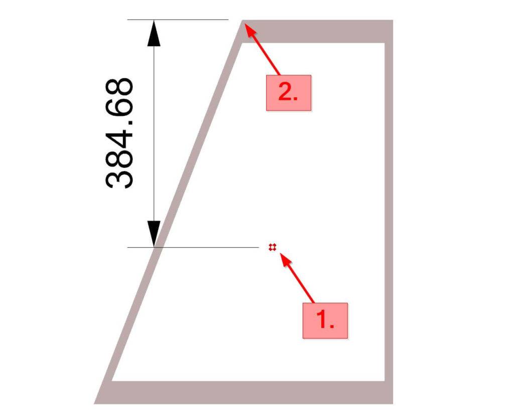
6. We can now measure the distance from the centroid to the most outer fibres.
Click on Linear Dimension >> Vertical Dimension
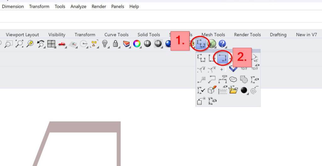
8. Click on the centroid point and a point on the top or bottom edge.
Let us know in the comments below 📝📝 if you could follow along or if you need a video tutorial for this, let us know.
Conclusion
Now, that you got an understanding of how to calculate the centroid of any section, you can learn about moment of inertia and section modulus, because these parameters are also cross-sectional properties and used in engineering.
If you want to learn where the section modulus and moment of inertia is used in structural engineering, then check out the following articles.📖📖
- Bending verification of a steel beam
- Lateral torsional buckling verification of a steel beam
- Timber flat roof beam design
I hope that this article helped you understand the centroid calculation and how to go further from here. In case you still have questions.
Let us know in the comments below. ✍️✍️
Centroid FAQ
A centroid is the center of mass or geometric center of a cross-section (rectangle, t section, i or h section, etc.). It is the point at which the shape would balance if it were suspended from that point.
The centroid is important in many engineering applications, as it is the point at which the shape/cross-section balances if it is suspended. It is also used in calculating moments of inertia and section modulus.
![Moment of Inertia Calculation [2026]](https://www.structuralbasics.com/wp-content/uploads/2023/01/Moment-of-Inertia-calculation-768x439.jpg)
![9+ Polar Moment Of Inertia Formulas [2026]](https://www.structuralbasics.com/wp-content/uploads/2023/09/2nd-polar-moment-of-inertia-formulas-768x439.jpg)
![The Pratt Truss Explained [2026]](https://www.structuralbasics.com/wp-content/uploads/2022/12/Pratt-truss-explained-768x439.jpg)
![12 Types of Columns in Buildings [The MOST Used]](https://www.structuralbasics.com/wp-content/uploads/2022/11/Types-of-columns-and-what-a-column-is-1-768x439.jpg)