Moment of Inertia Calculation [2026]
Are you an engineer, student, or someone who is looking to understand better how the moment of inertia is calculated?
The moment of inertia is a crucial parameter in determining the stability and strength of 3D objects used in engineering.
By understanding the moment of inertia calculation, you are one step closer to designing the most complex engineering elements.
In this beginner’s guide, we’ll walk you through the process of calculating the moment of inertia step-by-step.
Alright, let’s get started. 🚀🚀
What is The Moment of Inertia?
The moment of inertia is a key parameter used in the analysis and design of beams and other structural elements subject to bending. It is a measure of an object’s resistance to changes in rotational motion. It is used to calculate the bending stresses that a structural element will experience when subjected to a load.
In easy language, it’s a measure of how the material of a structural element is distributed with respect to the axis of rotation, like, for example, the centerline of a beam.
Before we look at the calculation of the moment of inertia, we have to clarify some concepts.
The moment of inertia is calculated by cross-sectional dimensions (height, width, etc.). The following paragraphs are for everyone who doesn’t know what a cross-section is or how to determine it from 3D objects.
Everyone, who knows about cross-sections, can directly jump into the calculation section.⬇️
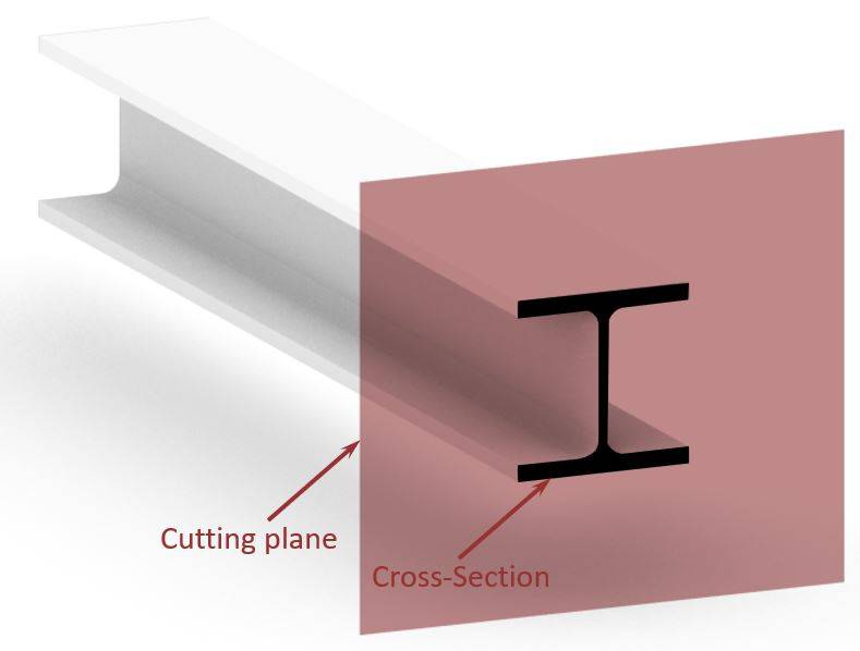
In structural engineering, cross-sections are determined by cutting through a 3D structural object, like a beam, column, slab, etc. perpendicular to its length. This is visualized in the following picture, where the cross-section of an I or H beam is shown.
Before we show how to calculate the moment of inertia of structural elements, here are some designs where the moment of inertia is used:
- Bending verification of flat roof timber beams
- Bending verification of timber rafters of collar beam roof
- Bending stress calculation of timber purlins
Enough talk, let’s get into the calculations.🧮🧮
Calculation of Moment of Inertia
The following expressions are the general formulas for the moment of inertia around the two main axes x and y used in structural engineering.
🙏🙏 Please don’t run away – those formulas scared me as well when I saw them at university. We will try to make it as practical as possible and bridge the gap to the formulas we are actually using as engineers.
But for everyone who doesn’t understand the following derivation or wants the shortcut: Scroll down to the parallel-axes theorem.⬇️⬇️
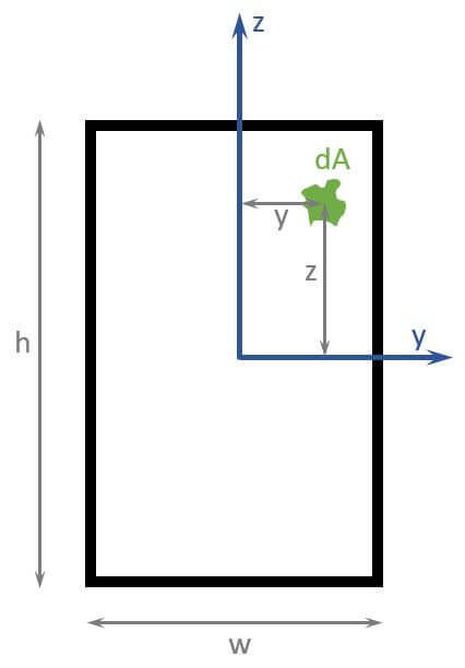
From this expression, we can actually calculate the formula of the moment of inertia of the rectangular cross-section shown in the picture above.
Now, when calculating $I_y$ dA can also be written as $w \, dz$ as the limits of the inner integral are from 0 to w.
$$I_y = 2 \int_0^{h/2} z^2 \cdot w \,dz$$
Let’s integrate further to get to the formula of the moment of inertia of a rectangle.
$$I_y = 2 [\frac{z^3}{3} \cdot w]_0^{h/2}$$
$$I_y = 2 [\frac{(h/2)^3}{3} \cdot w]$$
$$I_y = 2 [\frac{h^3}{24} \cdot w]$$
$$I_y = \frac{h^3 \cdot w}{12}$$
Voilà, this is the moment of inertia formula for the strong axis of a rectangular cross-section.
We could do the same now for the weak axis $I_z$ as well.
But let’s rather get to the general and “easier” formula for calculating the moment of inertia: It’s called the parallel-axes theorem.
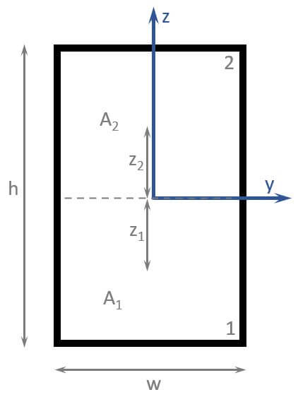
Let’s apply the parallel-axes theorem on the same rectangular cross-section again to see that we’ll get the same formula.
You can find the formulas for the moment of inertias of different shapes in this article.👈👈
$$I = \sum I_{0.1} + A_1 \cdot (z_1)^2 + \sum I_{0.2} + A_2 \cdot (z_2)^2$$
$$I = \frac{(\frac{h}{2})^3 \cdot w}{12} + \frac{h}{2} \cdot w \cdot (\frac{h}{4})^2 + \frac{(\frac{h}{2})^3 \cdot w}{12} + \frac{h}{2} \cdot w \cdot (\frac{h}{4})^2$$
$$I = 2 \frac{\frac{h^3}{8} \cdot w}{12} + 2 \frac{h}{2} \cdot w \cdot \frac{h^2}{16}$$
$$I = \frac{h^3 \cdot w}{48} + h \cdot w \cdot \frac{h^2}{16}$$
$$I = \frac{h^3 \cdot w}{48} + 3h \cdot w \cdot \frac{h^2}{48}$$
$$I = \frac{h^3 \cdot w}{12}$$
So, we basically got the same formula as before with the integral calculation.🎉🎉
Now, let’s insert some values in the formula.
w = 100 mm
h = 240 mm
This results in a moment of inertia of the strong axis of: ⬇️⬇️
$$I = \frac{(240mm)^3 \cdot 100mm}{12} = 1.152 \cdot 10^8 mm^4$$
However, this was only one example of the moment of inertia of 1 cross-section. Let’s have a look at what other sections exist.⬇️⬇️
Moment of Inertia for Different Cross-Sections
We have already written a Cheat sheet with the Moment of Inertia formulas for many different cross-sections around the strong and weak axis. Make sure to check that out, if you are looking for formulas.
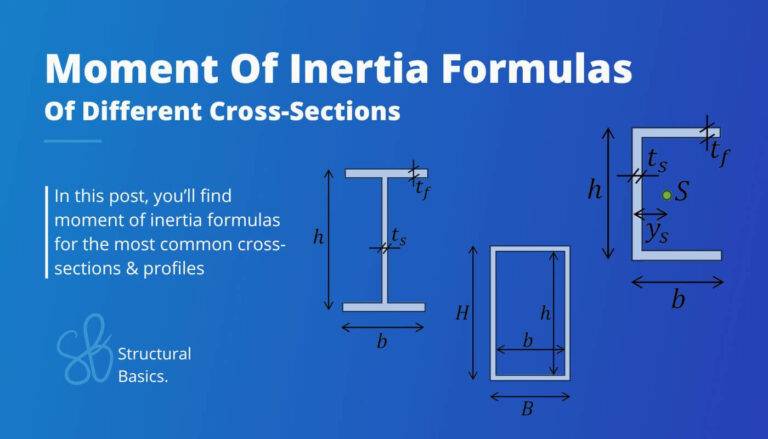
The following cross-sections exist and find use in engineering:
- Rectangular section
- I or H section
- Circular section
- Hollow circular section
- Hollow rectangular section
- C Channel
- T Section
- L Section
Units of Measurement
The unit of the cross-sectional area is mm4 [square milimeter] for most elements. However, if bigger elements such as bridge cross-section are designed, then m4 might be used.
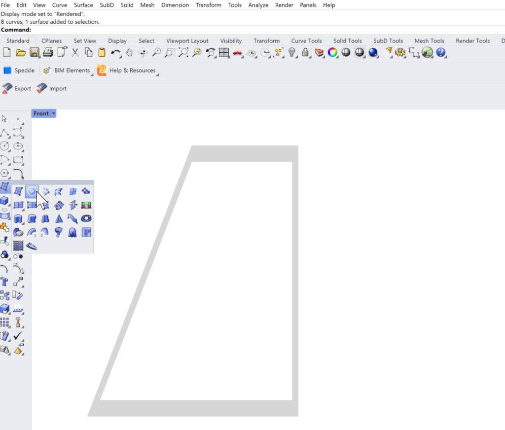
Calculation of Moment of Inertias of Complex Cross-Sections
In engineering, you sometimes come across complex cross-sections, like in the picture below. In a university course, I had to calculate the moment of inertia of that section. It was a beam used on the edge of a deck cross-section of a cable-stayed bridge.

To be honest with you – who likes to calculate the moment of inertia of such a profile?
It’s time-consuming and prone to errors.❌❌
Luckily, there is a great tool that can help us to calculate the area.
It’s Rhinoceros/Grasshopper.
1. We simply draw the geometry in Rhinoceros and create a surface from lines.
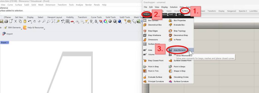
2. We then open Grasshopper.
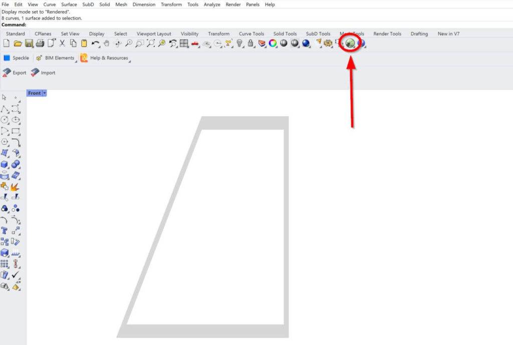
3. In Grasshopper, we click on Surface, Analysis and Area Moments.
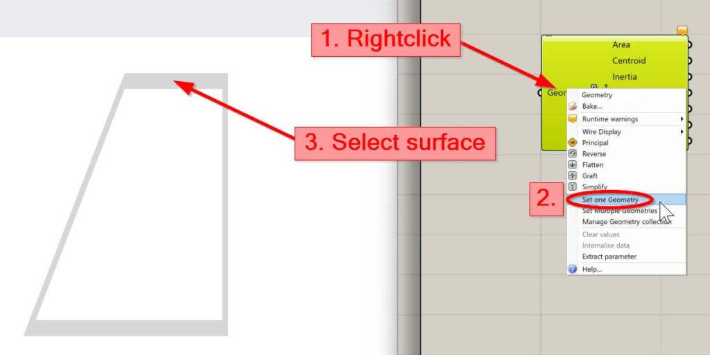
4. Right click on Geometry of the component, click on Set one Geometry and select the surface of the Cross-section.
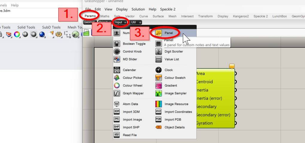
5. Last thing we need to do: Connect a panel with the output of the Area Moments component to see the result.
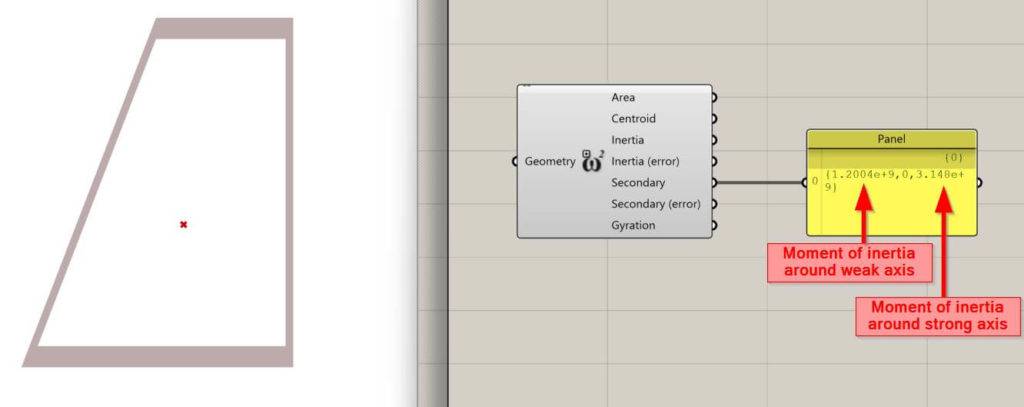
Now, we just connect the area output with the panel input, and we can see the calculated Moment of inertia.
❗Be careful, because the third value is the moment of inertia around the strong axis, while the first value is around the weak axis.
Let us know in the comments below⬇️⬇️, if you need a video tutorial for this or if you could follow along.
Conclusion
Now, that you got an understanding of how to calculate the moment of inertia, you can learn about section modulus and cross-sectional area, because these parameters are also cross-sectional properties and used in engineering.
If you want to learn where the moment of inertia is actually used in structural engineering, then check out the following articles.📖📖
I hope that this article helped you understand the moment of inertia calculation and how to go further from here. In case you still have questions.
Let us know in the comments below. ✍️✍️
Moment of Inertia FAQ
The moment of inertia is calculated using the formula I = ∑mr^2, where m is the mass of an object and r is the distance from the centroid of the mass to the axis of rotation. However, for typical cross-sections, formulas can be used to calculate the moment of inertia.
The moment of inertia describes how difficult it is to rotate an object around a specific axis. It is often used in physics and engineering to calculate the 3D object’s capacity to resist external forces.
![9+ Polar Moment Of Inertia Formulas [2026]](https://www.structuralbasics.com/wp-content/uploads/2023/09/2nd-polar-moment-of-inertia-formulas-768x439.jpg)