Collar Beam Design: Structural Calculation Of A Timber Roof
Are you building a roof or need to fix it, but you’re not sure which type of timber roof will be best?
The roof is a crucial component of a house and will affect the overall look and strength of a building, but it’s challenging to decide if a rafter, truss or maybe a collar beam roof is the right choice for the project. 🤔🤔
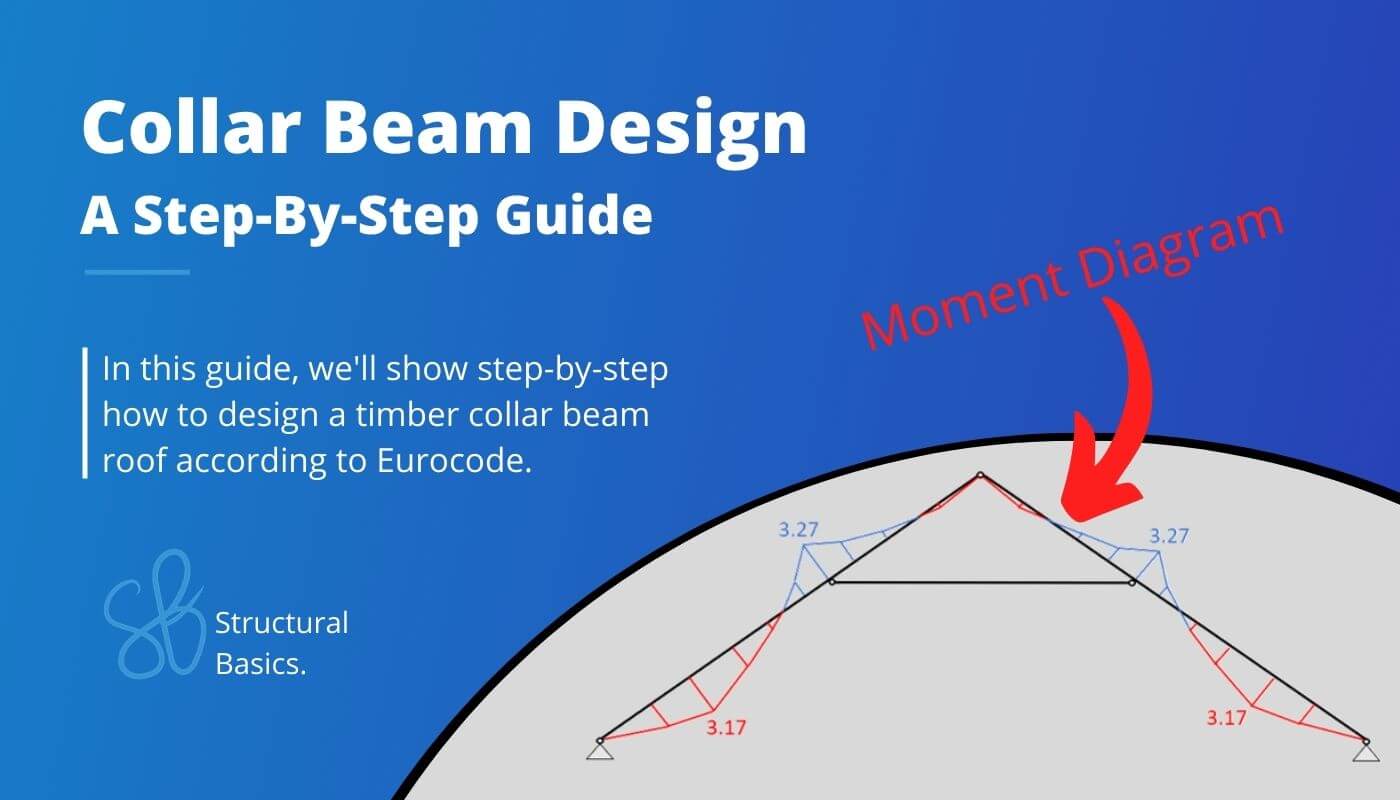
In this blog post, we’ll take a closer look at the collar beam roof and design step-by-step its timber elements according to the timber Eurocode EN 1995-1-1:2004.
Alright, so let’s dive into it. 🚀🚀
🙋♀️ What is a Collar Beam or Collar Roof?
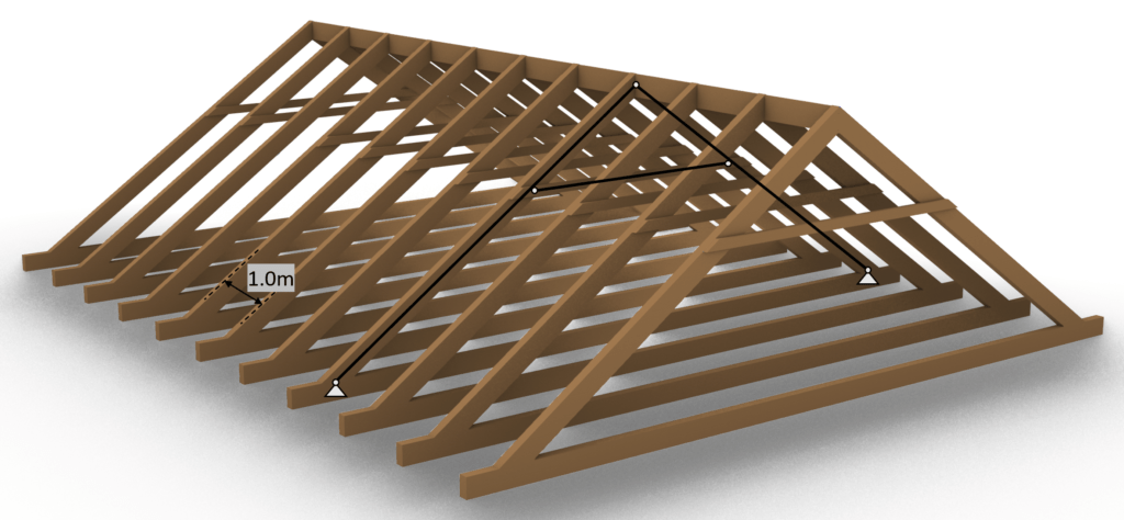
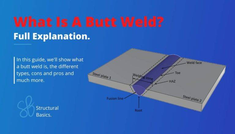
The collar beam roof is a roof type that consists of 2 rafters which are inclined and connected to each other at the top. The rafters are statically speaking beams and at some point between the rafters a horizontal element – the collar beam – connects to the rafters. The collar beam can, however, be modelled as a normal force only member depending on whether a additional floor is put on top of the collar beam or not.
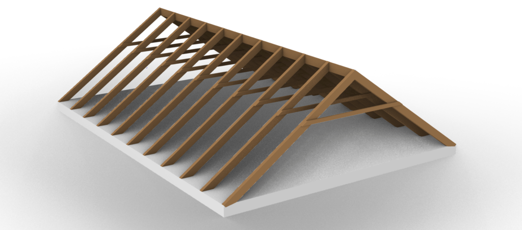
There are different ways to build the collar beam roof, meaning that the different elements can be built with different materials and systems.
One example of the collar beam type can be seen in the next picture where a timber beam is chosen as the collar beam and also a timber ceiling joist system is chosen as the structural floor.
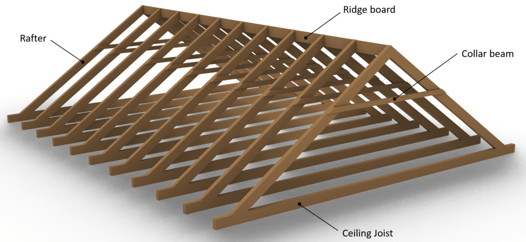
Sometimes the collar beam roof is supported by a concrete slab instead of a timber ceiling joist.
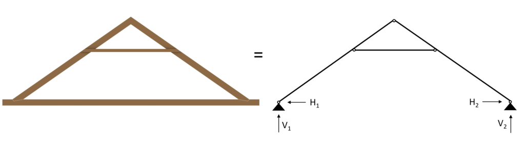
👆 Static System of the Collar Beam Roof
The static system of the collar beam roof is built up by 2 inclined rafters modelled as beams and connected to each other at the top with a hinge.
Those beams are supported with pinned supports at its lowest point or – in case of a overhang of the roof – close to the lowest point.
Between the start and the endpoint of the rafters, a horizontal beam or bar element is connected with hinges to both rafters.
This element is the collar beam.
The collar beam can act as a beam in all use cases and especially if there is an additional floor on top of it, but it can also be modelled as a bar element for the sake of simplicity – in case there is no additional floor on top.
The static system of the collar beam roof is visualized in the next picture.
To not lose context – the 2D static system represents the following rafters and beams.
But it can also represent any other section of rafters and beam.
The spacing between the rafters is set to 1m.
The collar beam roof can of course also have different layouts with wider spans, or a different position of the collar beam.
⬇️ Characteristic Loads
The loads will not be derived in this article. We explained the calculation of dead, live, wind and snow loads for pitched roofs thoroughly in previous articles.
The defined load values are estimations from the previous calculations.
| $g_{k}$ | 1.08 kN/m2 | Characteristic value of dead load |
| $q_{k}$ | 1.0 kN/m2 | Characteristic value of live load |
| $s_{k}$ | 0.53 kN/m2 | Characteristic value of snow load |
❗
The characteristic values of loads depend on a lot of different factors like location, National Annex and geometry of the building and roof to name just a few. Loads therefore need to be calculated for every structure.
As we also discussed in the article about the characteristic snow load, there are 3 different load cases, where only half of the value is applied on one pitched side but the full value on the other.
However, due to simplicity we only consider load case 1 in this tutorial which applies $s_{k} = 0.53 kN/m^2$ on both rafters.
We will split up the wind load from the above table due to the complexity of the wind with its wind areas and directions.
In this calculation, we will only focus on the external wind pressure for areas of 10 m2.
Wind direction front
| $w_{k.F}$ | -0.25(/0.35) kN/m2 | Characteristic value of wind load Area F |
| $w_{k.G}$ | -0.25(/0.35) kN/m2 | Characteristic value of wind load Area G |
| $w_{k.H}$ | -0.1(/0.2) kN/m2 | Characteristic value of wind load Area H |
| $w_{k.I}$ | -0.2(/0.0) kN/m2 | Characteristic value of wind load Area I |
| $w_{k.J}$ | -0.25(/0.0) kN/m2 | Characteristic value of wind load Area J |
Wind direction side
| $w_{k.F}$ | -0.55 kN/m2 | Characteristic value of wind load Area F |
| $w_{k.G}$ | -0.7 kN/m2 | Characteristic value of wind load Area G |
| $w_{k.H}$ | -0.4 kN/m2 | Characteristic value of wind load Area H |
| $w_{k.I}$ | -0.25 kN/m2 | Characteristic value of wind load Area I |
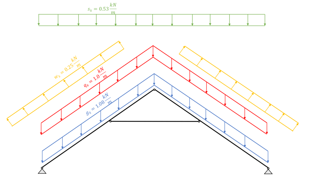
The following picture presents the static system of the collar beam roof with its line loads applied. The section that is presented in Figure: Collar beam roof | 2D static system representing rafters and beams is used for this example.
Due to simplicity, this tutorial looks only at the wind load from the side. Therefore, the wind load $w_{k.I} = -0.25 kN/m^2$ is applied to both rafters.
➕ Load Combinations
Luckily we have already written an extensive article about what load combinations are and how we use them. In case you need to brush up on it you can read the blog post here.
We choose to include $w_{k.I.}$ = -0.25 kN/m2 as the wind load in the load combinations, as this is the wind load that is applied to the section we look at, and to keep the calculation clean.
In principle, you should consider all load combinations.
However, with a bit more experience, you might be able to exclude some of the values.
In modern FE programs, multiple values for the wind load can be applied and load combinations automatically generated. So the computer is helping us a lot.
Just keep in mind that you should include all wind loads, but because of simplicity we do only consider 1 value in this article😁.
ULS Load combinations
❗
Due to the fact that the load direction and distribution is not the same, the loads can not simply be added up.
I know you might not understand what that means when you do load combinations the first time, but we did a whole article about what loads exist and how to apply them on a pitched roof 😎.
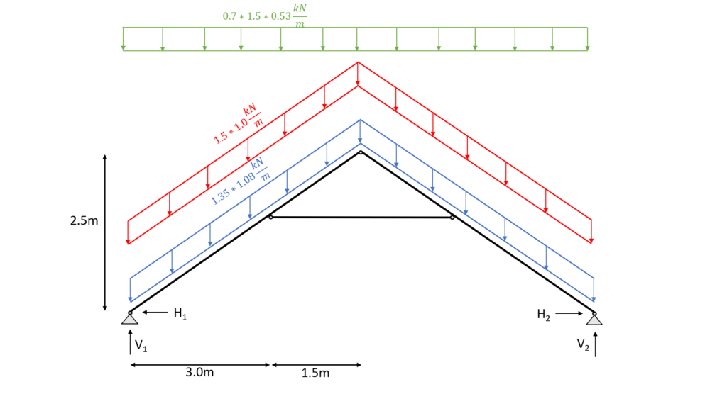
| LC1 | $1.35 * 1.08 \frac{kN}{m^2} $ |
| LC2 | $1.35 * 1.08 \frac{kN}{m^2} + 1.5 * 1.0 \frac{kN}{m^2}$ |
| LC3 | $1.35 * 1.08 \frac{kN}{m^2} + 1.5 * 1.0 \frac{kN}{m^2} + 0.7 * 1.5 * 0.53 \frac{kN}{m^2}$ |
| LC4 | $1.35 * 1.08 \frac{kN}{m^2} + 0 * 1.5 * 1.0 \frac{kN}{m^2} + 1.5 * 0.53 \frac{kN}{m^2}$ |
| LC5 | $1.35 * 1.08 \frac{kN}{m^2} + 1.5 * 1.0 \frac{kN}{m^2} + 0.7 * 1.5 * 0.53 \frac{kN}{m^2} + 0.6 * 1.5 * (-0.25 \frac{kN}{m^2}) $ |
| LC6 | $1.35 * 1.08 \frac{kN}{m^2} + 0 * 1.5 * 1.0 \frac{kN}{m^2} + 1.5 * 0.53 \frac{kN}{m^2} + 0.6 * 1.5 * (-0.25 \frac{kN}{m^2}) $ |
| LC7 | $1.35 * 1.08 \frac{kN}{m^2} + 0 * 1.5 * 1.0 \frac{kN}{m^2} + 0.7 * 1.5 * 0.53 \frac{kN}{m^2} + 1.5 * (-0.25 \frac{kN}{m^2}) $ |
| LC8 | $1.35 * 1.08 \frac{kN}{m^2} + 1.5 * 0.53 \frac{kN}{m^2} $ |
| LC9 | $1.35 * 1.08 \frac{kN}{m^2} + 1.5 * (-0.25 \frac{kN}{m^2}) $ |
| LC10 | $1.35 * 1.08 \frac{kN}{m^2} + 1.5 * 1.0 \frac{kN}{m^2} + 0.6 * 1.5 * (-0.25 \frac{kN}{m^2}) $ |
| LC11 | $1.35 * 1.08 \frac{kN}{m^2} + 1.5 * (-0.25 \frac{kN}{m^2}) + 0.7 * 1.5 * 0.53 \frac{kN}{m^2} $ |
| LC12 | $1.35 * 1.08 \frac{kN}{m^2} + 1.5 * 0.53 \frac{kN}{m^2} + 0.6 * 1.5 * (-0.25 \frac{kN}{m^2})$ |
Characteristic SLS Load combinations
| LC1 | $1.08 \frac{kN}{m^2} $ |
| LC2 | $1.08 \frac{kN}{m^2} + 1.0 \frac{kN}{m^2}$ |
| LC3 | $1.08 \frac{kN}{m^2} + 1.0 \frac{kN}{m^2} + 0.7 * 0.53 \frac{kN}{m^2}$ |
| LC4 | $1.08 \frac{kN}{m^2} + 1.0 \frac{kN}{m^2} + 0.6 * (-0.25 \frac{kN}{m^2})$ |
| LC5 | $1.08 \frac{kN}{m^2} + 1.0 \frac{kN}{m^2} + 0.7 * 0.53 \frac{kN}{m^2} + 0.6 * (-0.25 \frac{kN}{m^2}) $ |
| LC6 | $1.08 \frac{kN}{m^2} + 0 * 1.0 \frac{kN}{m^2} + 0.53 \frac{kN}{m^2} + 0.6 * (-0.25 \frac{kN}{m^2}) $ |
| LC7 | $1.08 \frac{kN}{m^2} + 0 * 1.0 \frac{kN}{m^2} + 0.7 * 0.53 \frac{kN}{m^2} + (-0.25 \frac{kN}{m^2}) $ |
| LC8 | $1.08 \frac{kN}{m^2} + 0.53 \frac{kN}{m^2}$ |
| LC9 | $1.08 \frac{kN}{m^2} + (-0.25 \frac{kN}{m^2}) $ |
| LC10 | $1.08 \frac{kN}{m^2} + 1.0 \frac{kN}{m^2} + 0.6 * (-0.25 \frac{kN}{m^2}) $ |
| LC11 | $1.08 \frac{kN}{m^2} + (-0.25 \frac{kN}{m^2}) + 0.7 * 0.53 \frac{kN}{m^2} $ |
| LC12 | $1.08 \frac{kN}{m^2} + 0 * 1.0 \frac{kN}{m^2} + 0.53 \frac{kN}{m^2}$ |
| LC13 | $1.08 \frac{kN}{m^2} + 0 * 1.0 \frac{kN}{m^2} + (-0.25 \frac{kN}{m^2})$ |
🪵 Rafter Timber Material
For this blog post/tutorial we are choosing a Structural timber C24. More comments on which timber material to pick and where to get the properties from were made here.
The following characteristic strength and stiffness parameters were found online from a manufacturer.
| Bending strength $f_{m.k}$ | 24 $\frac{N}{mm^2}$ |
| Tension strength parallel to grain $f_{t.0.k}$ | 14 $\frac{N}{mm^2}$ |
| Tension strength perpendicular to grain $f_{t.90.k}$ | 0.4 $\frac{N}{mm^2}$ |
| Compression strength parallel to grain $f_{c.0.k}$ | 21 $\frac{N}{mm^2}$ |
| Compression strength perpendicular to grain $f_{c.90.k}$ | 2.5 $\frac{N}{mm^2}$ |
| Shear strength $f_{v.k}$ | 4.0 $\frac{N}{mm^2}$ |
| E-modulus $E_{0.mean}$ | 11.0 $\frac{kN}{mm^2}$ |
| E-modulus, 5% quantile $E_{0.05}$ | 7.4 $\frac{kN}{mm^2}$ |
Modification factor $k_{mod}$
If you do not know what the modification factor $k_{mod}$ is, we wrote an explanation to it in a previous article, which you can check out.
Since we want to keep everything as short as possible, we are not going to repeat it in this article – we are only defining the values of $k_{mod}$.
For a residential house which is classified as Service class 1 according to EN 1995-1-1 2.3.1.3 we extract the following load durations for the different loads.
| Self-weight/dead load | Permanent |
| Live load, Snow load | Medium-term |
| Wind load | Instantaneous |
❗
The snow load can also be categorized as a short-term load. This depends on the location and the National Annex.
From EN 1995-1-1 Table 3.1 we get the $k_{mod}$ values for the load durations and a structural wood C24 (Solid timber).
| $k_{mod}$ | |||
|---|---|---|---|
| Self-weight/dead load | Permanent action | Service class 1 | 0.6 |
| Live load, Snow load | Medium term action | Service class 1 | 0.8 |
| Wind load | Instantaneous action | Service class 1 | 1.1 |
Partial factor $\gamma_{M}$
According to EN 1995-1-1 Table 2.3 the partial factor $\gamma_{M}$ is defined as
$\gamma_{M} = 1.3$
❗
Please be aware that those factors can vary from country to country. So please make sure to check those values with your National Annex.
📏 Assumption of Width and Height of Rafter and Collar Beam
We are defining the width w and height h of the C24 structural wood rafter cross-section as
Width w = 100 mm
Height h = 160 mm
And the values for the collar beam are defined as
Width w = 80 mm
Height h = 120 mm
💡We highly recommend doing any calculation in a program where you can always update values and not by hand on a piece of paper! Check out our beginners guide for SMath!
I made that mistake in my bachelor. In any course and even in my bachelor thesis, I calculated everything except the forces (FE program) on a piece of paper.
Now that we know the width and the height of the rafter cross-section we can calculate the Moment of inertias $I_{y}$ and $I_{z}$.
$I_{y} = \frac{w \cdot h^3}{12} = \frac{100mm \cdot (160mm)^3}{12} = 3.413 \cdot 10^7 mm^4 $
$I_{z} = \frac{w^3 \cdot h}{12} = \frac{(100mm)^3 \cdot 160mm}{12} = 1.333 \cdot 10^7 mm^4 $
And for the collar beam
$I_{y} = \frac{w \cdot h^3}{12} = \frac{80mm \cdot (120mm)^3}{12} = 1.152 \cdot 10^7 mm^4 $
$I_{z} = \frac{w^3 \cdot h}{12} = \frac{(80mm)^3 \cdot 120mm}{12} = 5.12 \cdot 10^6 mm^4 $
🆗 ULS Design
In the ULS (ultimate limit state) Design we verify the stresses in the timber members due to bending, shear and normal forces.
In order to calculate the stresses of our rafters and the collar beam, we need to calculate the Bending Moments, normal and shear forces due to different loads.
A FE or beam program is used to execute this task.
Calculation of bending moment, normal and shear forces
We use a FE program to calculate the bending moments, normal and shear forces.
Load combination 3 with live load as leading and snow load as reduced load leads to the highest results which we visualize.
Load combination 3
In our example the collar beam is modelled as a bar element, meaning that it can only take normal forces. Therefore the bending moments in this element equal 0.
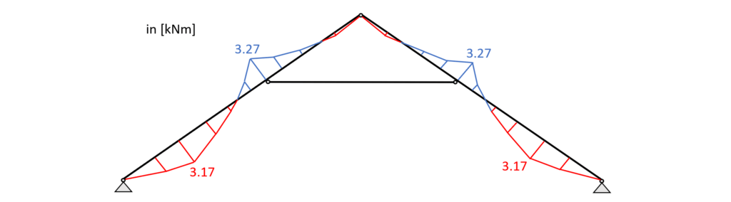
Load combination 3 – Bending moments
Load combination 3 – Shear forces
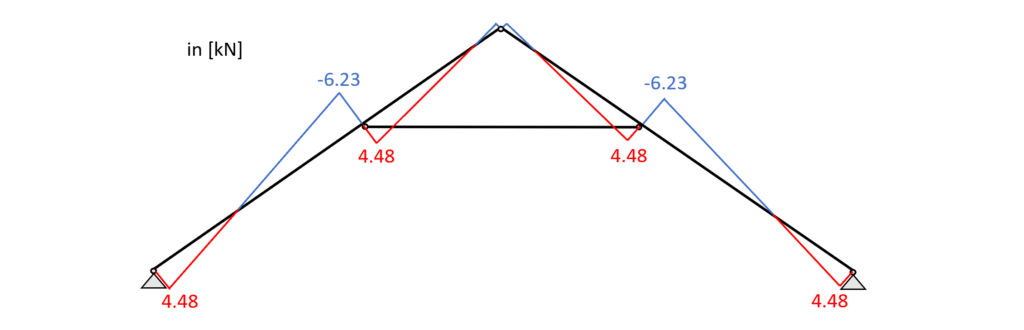
Load combination 3 – Normal forces
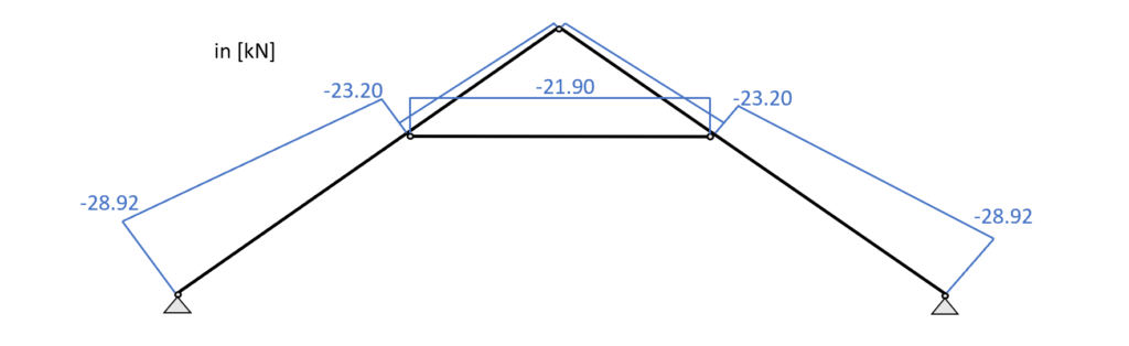
From the picture it can be seen that due to the leading load combination LC3 every element of the collar beam system acts in compression.
Bending and Compression Verification – Rafters
From the max. bending moment in the span (3.27 kNm) and the compression force (23.2 kN) in the same point we can calculate the stress in the most critical cross section.
Bending stress:
$\sigma_{m} = \frac{M_{d}}{I_{y}} \cdot \frac{h}{2} = \frac{3.27 kNm}{3.4 \cdot 10^{-5}} \cdot \frac{0.16m}{2} = 7.66 MPa$
Compression stress:
$\sigma_{c} = \frac{N_{d}}{w \cdot h} = \frac{23.2 kN}{0.1m \cdot 0.16m} = 1.46 MPa$
Resistance stresses of the timber material:
$ f_{d} = k_{mod} \cdot \frac{f_{k}}{\gamma_{m}} $
| LC3 (L-action) | $k_{mod.L} \cdot \frac{f_{m.k}}{\gamma_{m}} $ | $0.8 \cdot \frac{24 MPa}{1.3} $ | $14.77 MPa $ |
| LC3 (L-action) | $k_{mod.L} \cdot \frac{f_{c.k}}{\gamma_{m}} $ | $0.8 \cdot \frac{21 MPa}{1.3} $ | $12.92 MPa $ |
Utilization according to EN 1995-1-1 (6.19)
$\eta = (\frac{\sigma_{c}}{f_{c.d}})^2 + \frac{\sigma_{m}}{f_{m.d}} = 0.53 < 1.0$
✔️
Bending and Compression is therefore verified.
Shear Verification – Rafters
From the max. shear force (midsupport: 6.23 kN) we can calculate the shear stress in the most critical cross section.
Shear stress:
$\tau_{d} = \frac{3V}{2 \cdot w \cdot h} = \frac{3 \cdot 6.23 kN}{2 \cdot 0.1m \cdot 0.16m} = 0.584 MPa$
Resistance stresses of the timber material:
$ f_{v} = k_{mod.L} \cdot \frac{f_{v}}{\gamma_{m}} $
$ f_{v} = 0.8 \cdot \frac{4 MPa}{1.3} = 2.46 MPa$
Utilization according to EN 1995-1-1 (6.13)
$\eta = \frac{\tau_{v}}{f_{v}} = 0.24 < 1.0$
✔️
Shear is therefore verified.
Buckling Verification – Rafters
We assume that buckling out of the plane (z-direction) can be neglected because the rafters are held on the sides. Therefore, we can define the buckling length $l_{y}$ as
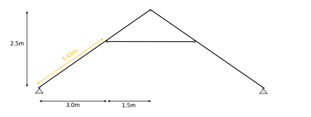
$l_{y} = 3.43m$
Radius of inertia
$i_{y} = \sqrt{\frac{I_{y}}{w \cdot h}} = 0.046m$
Slenderness ratio
$\lambda_{y} = \frac{l_{y}}{i_{y}} = 74.26$
Relative slenderness ratio (EN 1995-1-1 (6.21))
$ \lambda_{rel.y} = \frac{\lambda_{y}}{\pi} \cdot \sqrt{\frac{f_{c.0.k}}{E_{0.g.05}}} = 1.26$
$\beta_{c}$ factor for solid timber (EN 1995-1-1 (6.29))
$\beta_{c} = 0.2$
Instability factor (EN 1995-1-1 (6.27))
$k_{y} = 0.5 \cdot (1+ \beta_{c} \cdot (\lambda_{rel.y} – 0.3) + \lambda_{rel.y}^2) = 1.39$
Buckling reduction coefficient (EN 1995-1-1 (6.25))
$k_{c.y} = \frac{1}{k_{y} + \sqrt{k_{y}^2 – \lambda_{rel.y}^2}} = 0.51$
Utilization (EN 1995-1-1 (6.23))
$\frac{\sigma_{c}}{k_{c.y} \cdot f_{c.d}} + \frac{\sigma_{m}}{f_{m.d}} = 0.74$
✔️
Buckling is verified for the rafter.
Compression Verification – Collar beam
From the max. compression force (21.9 kN) in the collar beam we can calculate the stress in the most critical cross section.
Compression stress:
$\sigma_{c} = \frac{N_{d}}{w \cdot h} = \frac{21.9 kN}{0.08m \cdot 0.12m} = 2.28 MPa$
Resistance stresses of the timber material:
$ f_{d} = k_{mod} \cdot \frac{f_{k}}{\gamma_{m}} $
| LC3 (L-action) | $k_{mod.L} \cdot \frac{f_{c.k}}{\gamma_{m}} $ | $0.8 \cdot \frac{21 MPa}{1.3} $ | $12.92 MPa $ |
Utilization according to EN 1995-1-1 (6.19)
$\eta = \frac{\sigma_{c}}{f_{c.d}} = 0.18 < 1.0$
✔️
Compression is verified for the collar beam.
Buckling Verification – Collar beam
Buckling out of plane is assumed to have the same buckling length as in plane. Therefore we can define the buckling lengths $l_{y}$ and $l_{z}$ as
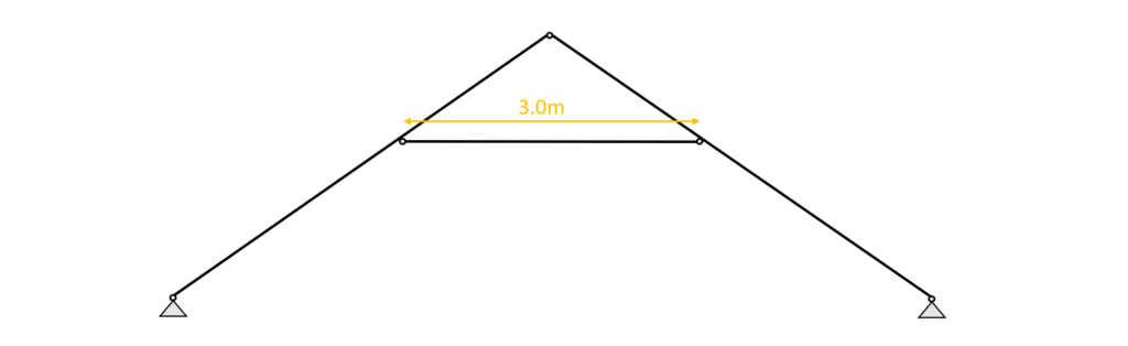
$l_{y} = 3.0m$
$l_{z} = 3.0m$
Radius of inertia
$i_{y} = \sqrt{\frac{I_{y}}{w \cdot h}} = 0.035m$
$i_{z} = \sqrt{\frac{I_{z}}{w \cdot h}} = 0.023m$
Slenderness ratio
$\lambda_{y} = \frac{l_{y}}{i_{y}} = 86.6$
$\lambda_{z} = \frac{l_{z}}{i_{z}} = 129.9$
Relative slenderness ratio (EN 1995-1-1 (6.21))
$ \lambda_{rel.y} = \frac{\lambda_{y}}{\pi} \cdot \sqrt{\frac{f_{c.0.k}}{E_{0.g.05}}} = 1.47$
$ \lambda_{rel.z} = \frac{\lambda_{z}}{\pi} \cdot \sqrt{\frac{f_{c.0.k}}{E_{0.g.05}}} = 2.2$
$\beta_{c}$ factor for solid timber (EN 1995-1-1 (6.29))
$\beta_{c} = 0.2$
Instability factor (EN 1995-1-1 (6.27))
$k_{y} = 0.5 \cdot (1+ \beta_{c} \cdot (\lambda_{rel.y} – 0.3) + \lambda_{rel.y}^2) = 1.7$
$k_{z} = 0.5 \cdot (1+ \beta_{c} \cdot (\lambda_{rel.z} – 0.3) + \lambda_{rel.z}^2) = 3.12$
Buckling reduction coefficient (EN 1995-1-1 (6.25))
$k_{c.y} = \frac{1}{k_{y} + \sqrt{k_{y}^2 – \lambda_{rel.y}^2}} = 0.4$
$k_{c.z} = \frac{1}{k_{z} + \sqrt{k_{z}^2 – \lambda_{rel.z}^2}} = 0.19$
Utilization (EN 1995-1-1 (6.23))
$\frac{\sigma_{c}}{k_{c.y} \cdot f_{c.d}}= 0.45$
$\frac{\sigma_{c}}{k_{c.z} \cdot f_{c.d}}= 0.94$
✔️
Buckling is therefore verified for the collar beam.
✔️ SLS Design
We also discussed the SLS design a bit more in detail in a previous article. In this blog post we are not explaining too much but rather show the calculations😊
Instantaneous deformation $u_{inst}$
$u_{inst}$ (instantaneous deformation) of our beam can be calculated with the load of the characteristic load combination.
As for the bending moments, shear and axial forces, we are using a FE program to calculate the deflections due to our Load combinations.
LC 3 of the characteristic SLS load combinations leads to the largest deflection u.
$u_{inst}$ = 6.9 mm
Unfortunately, EN 1995-1-1 Table 7.2 recommends values for $w_{inst}$ only for “Beams on two supports” and “Cantilevering beams” and not for a collar beam system like in this case.
However, the limits of the deflection can be agreed upon with the client and the structure is not collapsing due to too large deflections if the rafter is verified for all ULS calculations.
So for the sake of this tutorial we are using the value for “Beam on two supports” from EN 1995-1-1 Table 7.2.
But my question to you: What limit would you use in this case? Let me know in the comments below.
$w_{inst}$ = l/300 = 3.43m/300 = 11.43 mm
Utilization
$\eta = \frac{u_{inst}}{w_{inst}} = \frac{6.9mm}{11.43mm} = 0.604$
✔️
The Instantaneous deflection is verified for the rafter(s).
Final deformation $u_{fin}$
$u_{fin}$ (final deformation) of our beam/rafter can be calculated by adding the creep deformation $u_{creep}$ to the instantaneous deflection $u_{inst}$.
Therefore, we will calculate the creep deflection with a FE program.
This might be a bit quick, but we have already covered the basics in the article about the timber beam dimensioning.
So check that out if you want to know exactly how to calculate $u_{creep}$ by hand.
The creep deformation of LC3 is calculated as
$u_{creep}$ = 1.98mm
Adding the creep to the instantaneous deflection leads to the final deflection.
$u_{fin} = u_{inst} + u_{creep} = 6.9mm + 1.98mm= 8.88mm$
Limit of $u_{fin}$ according to EN 1995-1-1 Table 7.2
$w_{fin}$ = l/150 = 3.43m/150 = 22.87 mm
Utilization
$\eta = \frac{u_{fin}}{w_{fin}} = \frac{8.88mm}{22.87mm} = 0.388$
✔️
The final deflection is verified for the rafter.
🤝 Conclusion
Now that the rafters and the collar beam are verified for compression, bending, buckling and deflection, we can finally say that the cross-section heights and widths are verified – check✔️✔️.
If you are new to structural design, then check out more of our design tutorials where you can also learn how to design other wood elements such as
But now, I would like to hear from you: Have you already designed a collar beam in university or at your work? And which semester was that in? Tell us a bit about the structure, as we all want to learn from each other. ✍️✍️
🙋♂️ Collar Beam FAQ
Collar beams are horizontal members that connect the rafters of a roof. They are usually located near the peak of the roof and the main material used is wood.
Collar beams prevent the rafters from spreading apart under the weight and external loads (snow, wind, live) of the roof.
One potential downside to using collar beams is that they can reduce the height of the usable space in the attic or upper level of a building.
![How To Dimension Rafters Of Purlin Roofs? [Structural Guide]](https://www.structuralbasics.com/wp-content/uploads/2022/03/How-to-design-rafters-of-purlin-roofs-768x439.jpg)
![Butt Weld Design [Structural Calculation]](https://www.structuralbasics.com/wp-content/uploads/2023/09/Butt-weld-design-768x439.jpg)
Hey!
I have been following your work for a while and learnt some things aswell. Good work on these guides!
Also I have tried to research about double wood beams connected together, so that they work together and bear higher load (like massive glued timber beams) . Haven’t found anything useful yet (especially how to calculate beam connections and the whole beam load bearing).
Do you have experience about that kind of beams or heard about it?
Respectfully,
Rain
Hi Rain,
Thanks for your message.
I am not sure I fully understand what you mean by double wood beams.
I assume you mean 2 beams places next to each other (horizontally) with a small gap or no gap at all.
This type of structure is very beneficial for
1. Connecting a beam to a column or diagonal member of a truss
2. Structures where the beam height is limited
The load bearing capacity is twice as high as for 1 beam because the moment of inertia is double as you double the width: I=h^3•(2w)/12.
You can follow this step-by-step guide (https://www.structuralbasics.com/how-to-dimension-a-timber-beam/), just consider double the moment of inertia when verifying the beam.
Now, when it comes to the connections, it depends what elements you want to connect. But let’s say you want to connect a timber beam with a timber column as a hinge connection. I would use bolts or dowels and try to verify it as a timber to timber connection (EN 1995-1-1). Don’t forget to verify spacing and edge distances. If that doesn’t verify then include steel plates. For some of the parameters you can follow https://www.structuralbasics.com/timber-steel-connection-beam-to-beam-an-example-of-a-flat-roof/
Hope that helped!
Laurin