Rafter Roof Design [Step-By-Step Guide]
Designing a rafter roof for a building project can be challenging. 🙆♂️🙆♂️
You need to know what loads act on the roof, how to do load combinations, which static system applies to the rafters and then finally how to design timber elements and ensure the structure is structurally sound.
So in this post, we’ll show exactly, step-by-step, how to design a timber rafter roof according to Eurocode EN 1995-1-1:2004.
Not much more talk, let’s dive into it.
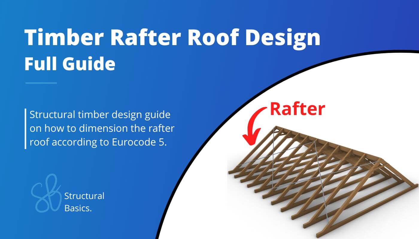
What is a rafter roof?
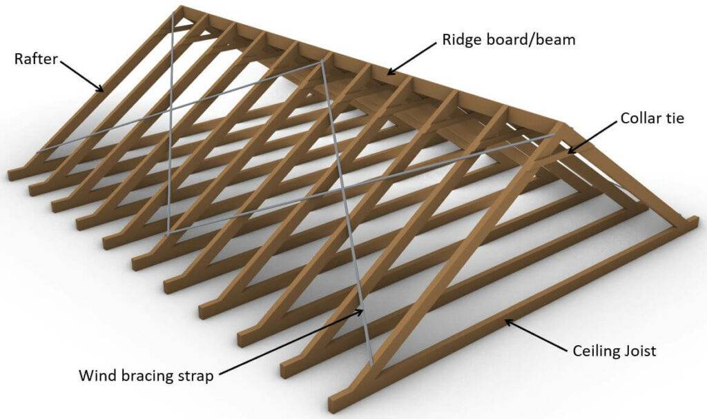
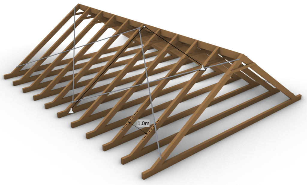
The rafter roof consists of 2 rafters which are inclined and connected to each other at the top with a ridge board. The rafters are statically speaking beams and have usually a connection/support at the bottom (floor) and the top (2nd rafter or ridge board). Depending on the design the rafters can also be cantilevered to create an overhang of the roof.
As already mentioned, there is different ways to build the rafter roof, meaning that the different elements can be built with different materials and systems.
One example of the rafter roof type can be seen in the picture above where a timber beam is chosen as the ceiling joist which takes up the horizontal support forces of the rafters in, mostly, tension. A concrete slab could be used as an alternative.
A steel wind bracing strap is furthermore chosen as the wind bracing system. Alternatively, you could also use plates such as OSB boards.
Types Of Rafters
Common Rafter
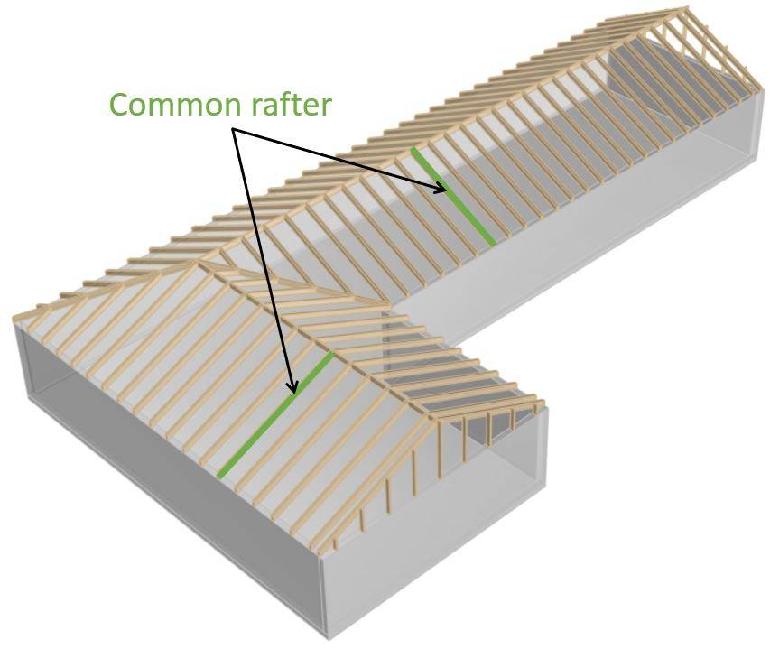
The common rafters are inclined members of the rafter roof that are supported by the ridge and the walls. The common rafters are equally spaced and support the roof cover.
Valley Rafter
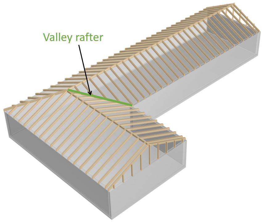
Valley rafters are placed where two roof planes intersect. These rafters run diagonally from the walls to the ridge and support the rafters that run perpendicular to the ridge.
Valley rafters have usually a bigger cross-section as they are carrying more load.
Hip Rafter
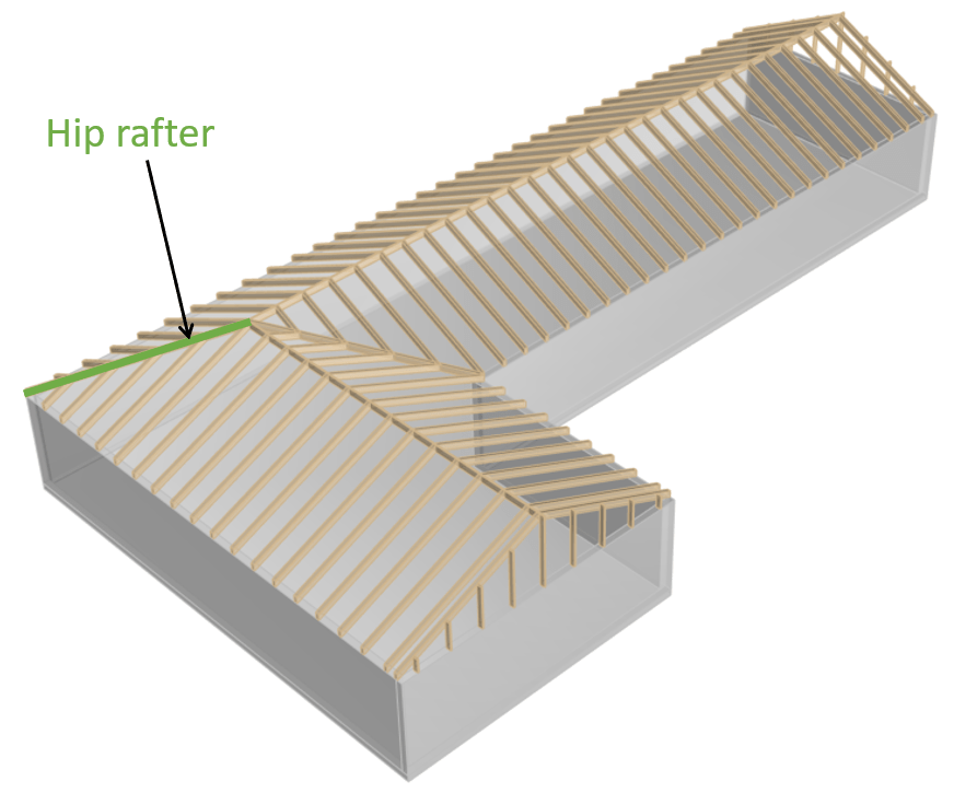
Hip rafters are structural members of the rafter roof which are used in the outer corners running diagonally from the intersection of two walls to the intersection of the ridge.
As the valley rafters, hip rafters support the rafters running perpendicular to the ridge. Also the hip rafters have a bigger cross-section than the common rafters as they carry more load.
Ridge
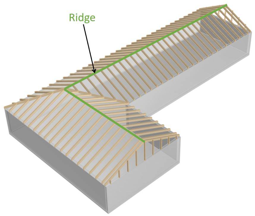
The ridge is the highest horizontal element of a rafter roof. The ridge is where the two rafters with inclination meet.
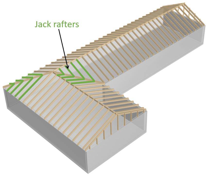
Jack Rafter
Jack rafters are shorter than common rafters as they terminate at the hip or valley rafters.
Static system of the rafter roof
The static system of the rafter roof is built up by 2 inclined rafters modelled as beams and connected to each other at the top with a hinge.
Those beams are supported with pinned supports at its lowest point or – in case of a cantilevered overhang of the roof – close to the lowest point.
The static system of the rafter roof is visualized in the next picture. ⬇️⬇️
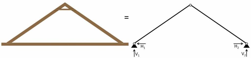
It consists of 2 pin supports and a hinge connection at the top.
To not lose context – the 2D static system represents the following rafters. 👇👇
The rafter roof can of course also have different layouts with wider spans or steeper inclination.
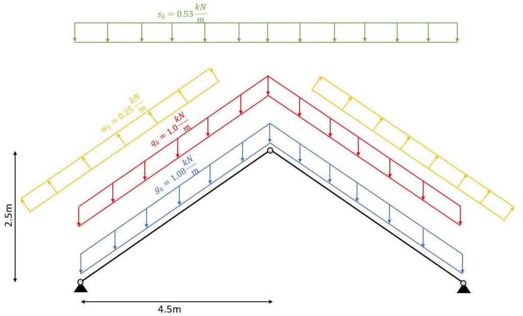
Characteristic Loads – Rafter roof
The loads will not be derived in this article. We explained the calculation of dead, live, wind and snow loads for pitched roofs thoroughly in previous articles.
We’ll use the following load assumptions for the design of the rafters:
| gk | 1.08 kN/m2 | Characteristic value of dead load |
| qk | 1.0 kN/m2 | Characteristic value of live load |
| sk | 0.53 kN/m2 | Characteristic value of snow load |
❗
The characteristic values of loads depend on a lot of different factors like location, National Annex and geometry of the building and roof to name just a few. Loads therefore need to be calculated for every structure.
As we also discussed in the article about the characteristic snow load, that there are 3 different load cases, where only half of the value is applied on one pitched side but the full value on the other.
However, due to simplicity we only consider load case 1 in this tutorial which applies sk = 0.53 kN/m2 on both rafters.
We will split up the wind load from the above table due to the complexity of the wind with its wind areas and directions.
In this calculation, we will only focus on the external wind pressure for areas of 10 m2.
Wind direction front
| wk.F | -0.25(/0.35) kN/m2 | Characteristic value of wind load Area F |
| wk.G | -0.25(/0.35) kN/m2 | Characteristic value of wind load Area G |
| wk.H | -0.1(/0.2) kN/m2 | Characteristic value of wind load Area H |
| wk.I | -0.2(/0.0) kN/m2 | Characteristic value of wind load Area I |
| wk.J | -0.25(/0.0) kN/m2 | Characteristic value of wind load Area J |
Wind direction side
| wk.F | -0.55 kN/m2 | Characteristic value of wind load Area F |
| wk.G | -0.7 kN/m2 | Characteristic value of wind load Area G |
| wk.H | -0.4 kN/m2 | Characteristic value of wind load Area H |
| wk.I | -0.25 kN/m2 | Characteristic value of wind load Area I |
Due to simplicity, in this tutorial we only use the wind load from the side. Therefore, the wind load wk.I = -0.25 kN/m2 is applied to both rafters.
💡
Line loads:
Since the distance between the rafters is set to 1.0 m the line loads have the same values as the area loads. If the spacing (distance between rafters) was 0.8 m then all area loads would need to be multiplied by 0.8 m.
Load combinations – Rafter roof
Luckily we have already written an extensive article about what load combinations are and how we use them. In case you need to brush up on it you can read the blog post here.
We choose to include wk.I = -0.25 kN/m2 as the wind load in the load combinations, as this is the wind load that is applied to the section we look at, and to keep the calculation clean.
In principle, you should consider all load cases. However, with a bit more experience, you might be able to exclude some of the values.
In modern FE programs, multiple values for the wind load can be applied and load combinations are automatically generated. So the computer is helping us a lot.
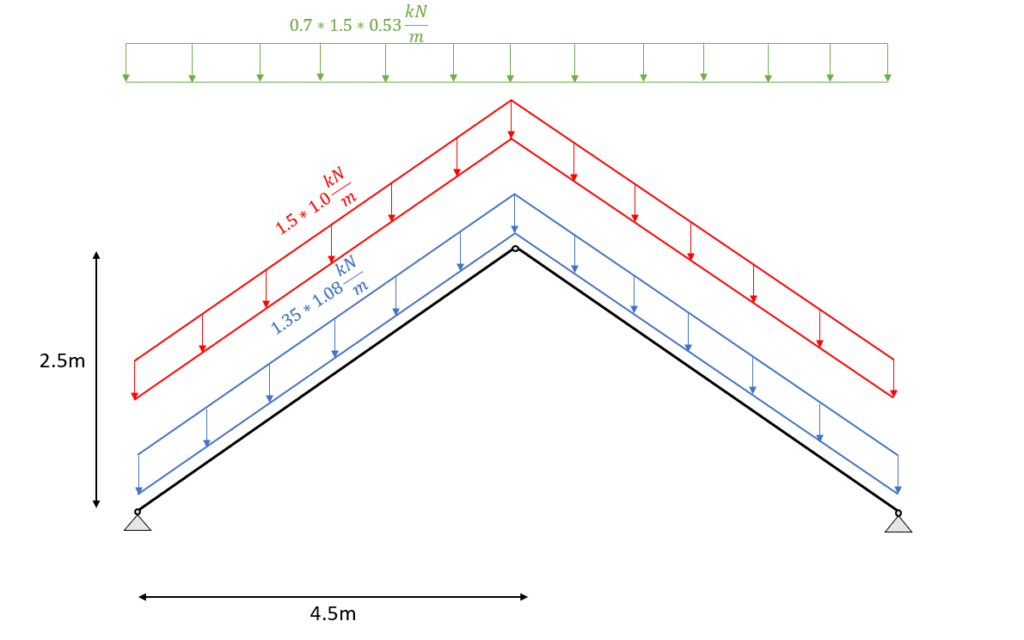
ULS Load combinations
❗
Due to the fact that the load direction and distribution is not the same, the loads can not simply be added up.
I know you might not understand what that means when you do load combinations the first time, but we did a whole article about what loads exist and how to apply them on a pitched roof.
| LC1 | $1.35 \cdot 1.08 \frac{kN}{m^2} $ |
| LC2 | $1.35 \cdot 1.08 \frac{kN}{m^2} + 1.5 \cdot 1.0 \frac{kN}{m^2}$ |
| LC3 | $1.35 \cdot 1.08 \frac{kN}{m^2} + 1.5 \cdot 1.0 \frac{kN}{m^2} + 0.7 \cdot 1.5 \cdot 0.53 \frac{kN}{m^2}$ |
| LC4 | $1.35 \cdot 1.08 \frac{kN}{m^2} + 0 \cdot 1.5 \cdot 1.0 \frac{kN}{m^2} + 1.5 \cdot 0.53 \frac{kN}{m^2}$ |
| LC5 | $1.35 \cdot 1.08 \frac{kN}{m^2} + 1.5 \cdot 1.0 \frac{kN}{m^2} + 0.7 \cdot 1.5 \cdot 0.53 \frac{kN}{m^2} + 0.6 \cdot 1.5 \cdot (-0.25 \frac{kN}{m^2}) $ |
| LC6 | $1.35 \cdot 1.08 \frac{kN}{m^2} + 0 \cdot 1.5 \cdot 1.0 \frac{kN}{m^2} + 1.5 \cdot 0.53 \frac{kN}{m^2} + 0.6 \cdot 1.5 \cdot (-0.25 \frac{kN}{m^2}) $ |
| LC7 | $1.35 \cdot 1.08 \frac{kN}{m^2} + 0 \cdot 1.5 \cdot 1.0 \frac{kN}{m^2} + 0.7 \cdot 1.5 \cdot 0.53 \frac{kN}{m^2} + 1.5 \cdot (-0.25 \frac{kN}{m^2}) $ |
| LC8 | $1.35 \cdot 1.08 \frac{kN}{m^2} + 1.5 \cdot 0.53 \frac{kN}{m^2} $ |
| LC9 | $1.35 \cdot 1.08 \frac{kN}{m^2} + 1.5 \cdot (-0.25 \frac{kN}{m^2}) $ |
| LC10 | $1.35 \cdot 1.08 \frac{kN}{m^2} + 1.5 \cdot 1.0 \frac{kN}{m^2} + 0.6 \cdot 1.5 \cdot (-0.25 \frac{kN}{m^2}) $ |
| LC11 | $1.35 \cdot 1.08 \frac{kN}{m^2} + 1.5 \cdot (-0.25 \frac{kN}{m^2}) + 0.7 \cdot 1.5 \cdot 0.53 \frac{kN}{m^2} $ |
| LC12 | $1.35 \cdot 1.08 \frac{kN}{m^2} + 1.5 \cdot 0.53 \frac{kN}{m^2} + 0.6 \cdot 1.5 \cdot (-0.25 \frac{kN}{m^2})$ |
You can also use our free load combination generator to create all ULS load combinations automatically.
Characteristic SLS Load combinations
| LC1 | $1.08 \frac{kN}{m^2} $ |
| LC2 | $1.08 \frac{kN}{m^2} + 1.0 \frac{kN}{m^2}$ |
| LC3 | $1.08 \frac{kN}{m^2} + 1.0 \frac{kN}{m^2} + 0.7 \cdot 0.53 \frac{kN}{m^2}$ |
| LC4 | $1.08 \frac{kN}{m^2} + 1.0 \frac{kN}{m^2} + 0.6 \cdot (-0.25 \frac{kN}{m^2})$ |
| LC5 | $1.08 \frac{kN}{m^2} + 1.0 \frac{kN}{m^2} + 0.7 \cdot 0.53 \frac{kN}{m^2} + 0.6 \cdot (-0.25 \frac{kN}{m^2}) $ |
| LC6 | $1.08 \frac{kN}{m^2} + 0 \cdot 1.0 \frac{kN}{m^2} + 0.53 \frac{kN}{m^2} + 0.6 \cdot (-0.25 \frac{kN}{m^2}) $ |
| LC7 | $1.08 \frac{kN}{m^2} + 0 \cdot 1.0 \frac{kN}{m^2} + 0.7 \cdot 0.53 \frac{kN}{m^2} + (-0.25 \frac{kN}{m^2}) $ |
| LC8 | $1.08 \frac{kN}{m^2} + 0.53 \frac{kN}{m^2}$ |
| LC9 | $1.08 \frac{kN}{m^2} + (-0.25 \frac{kN}{m^2}) $ |
| LC10 | $1.08 \frac{kN}{m^2} + 1.0 \frac{kN}{m^2} + 0.6 \cdot (-0.25 \frac{kN}{m^2}) $ |
| LC11 | $1.08 \frac{kN}{m^2} + (-0.25 \frac{kN}{m^2}) + 0.7 \cdot 0.53 \frac{kN}{m^2} $ |
| LC12 | $1.08 \frac{kN}{m^2} + 0 \cdot 1.0 \frac{kN}{m^2} + 0.53 \frac{kN}{m^2}$ |
| LC13 | $1.08 \frac{kN}{m^2} + 0 \cdot 1.0 \frac{kN}{m^2} + (-0.25 \frac{kN}{m^2})$ |
Rafter timber material
For this blog post/tutorial we are choosing a structural timber C24.
The following characteristic strength and stiffness parameters were found online from a manufacturer.
| Bending strength fm.k | 24 N/mm2 |
| Tension strength parallel to grain ft.0.k | 14 N/mm2 |
| Tension strength perpendicular to grain ft.90.k | 0.4 N/mm2 |
| Compression strength parallel to grain fc.0.k | 21 N/mm2 |
| Compression strength perpendicular to grain fc.90.k | 2.5 N/mm2 |
| Shear strength fv.k | 4.0 N/mm2 |
| E-modulus E0.mean | 11.0 kN/mm2 |
| E-modulus E0.g.05 | 7.4 kN/mm2 |
Modification factor kmod
If you do not know what the modification factor kmod is, we wrote an explanation to it in a previous article, which you can check out.
Since we want to keep everything as short as possible, we are not going to repeat it in this article – we are only defining the values of kmod.
For a residential house which is classified as Service class 1 according to EN 1995-1-1 2.3.1.3 we extract the following load durations for the different loads.
| Self-weight/dead load | Permanent |
| Live load, Snow load | Medium-term |
| Wind load | Instantaneous |
❗
The snow load can also be categorized as a short-term load. This depends on the location and the National Annex.
From EN 1995-1-1 Table 3.1 we get the kmod values for the load durations and a structural wood C24 (Solid timber).
| Self-weight/dead load | Permanent action | Service class 1 | 0.6 |
| Live load, Snow load | Medium term action | Service class 1 | 0.8 |
| Wind load | Instantaneous action | Service class 1 | 1.1 |
Partial factor $\gamma_{M}$
According to EN 1995-1-1 Table 2.3 the partial factor $\gamma_{M}$ is defined as
$$\gamma_{M} = 1.3$$
❗
Please be aware that those factors can vary from country to country. So please make sure to check those values with your National Annex.
Assumption of width and height of rafter
We are defining the width w and height h of the C24 structural wood rafter cross-section as
| Width | w = 100 mm |
| Height | h = 240 mm |
💡 We highly recommend doing any calculation in a program where you can always update values and not by hand on a piece of paper!
I made that mistake in my bachelor. In any course and even in my bachelor thesis, I calculated everything except the forces (FE program) on a piece of paper.
Now that we know the width and the height of the rafter cross-section we can calculate the Moment of inertias Iy and Iz.
$$I_{y} = \frac{w \cdot h^3}{12} = \frac{100mm \cdot (240mm)^3}{12} = 1.152 \cdot 10^8 mm^4 $$
$$I_{z} = \frac{w^3 \cdot h}{12} = \frac{(100mm)^3 \cdot 240mm}{12} = 2.0 \cdot 10^7 mm^4 $$
ULS Design
In the ULS (ultimate limit state) design we verify the stresses in the timber members due to bending, shear and normal forces.
You can check out our YouTube video tutorial on how to design timber beams. 👇👇
In order to calculate the stresses of the rafters, we need to calculate the bending moments, normal and shear forces due to different loads. A FE or beam program is used to execute this task.
Calculation of bending moment, normal and shear forces – Rafter roof
We use a FE programm to calculate the bending moments, normal and shear forces.
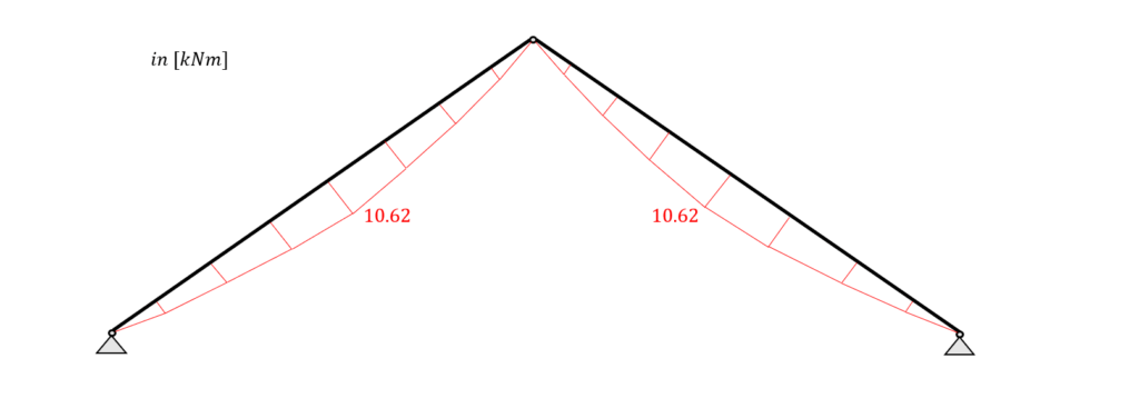
Load combination 3 with live load as leading and snow load as reduced load leads to the highest results which we visualize.
Load combination 3 – Loads
Load combination 3 – Bending moments
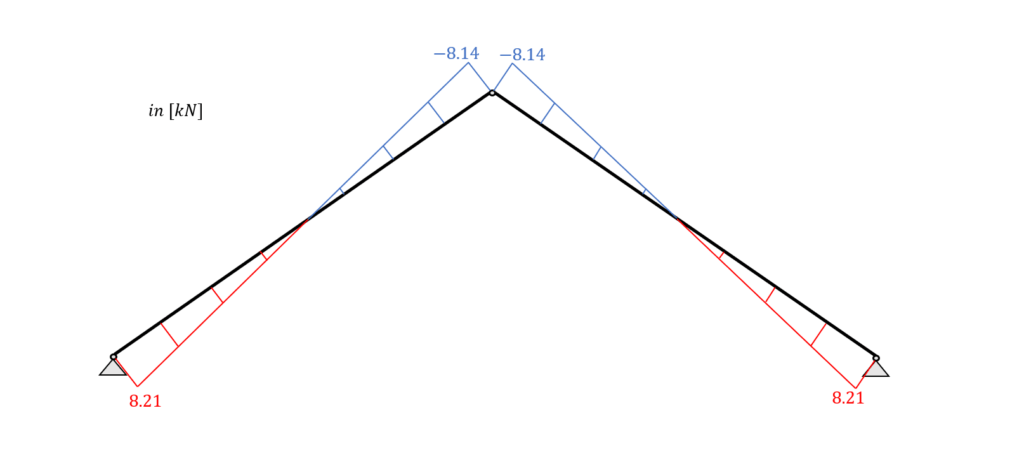
Load combination 3 – Shear forces
Load combination 3 – Normal forces
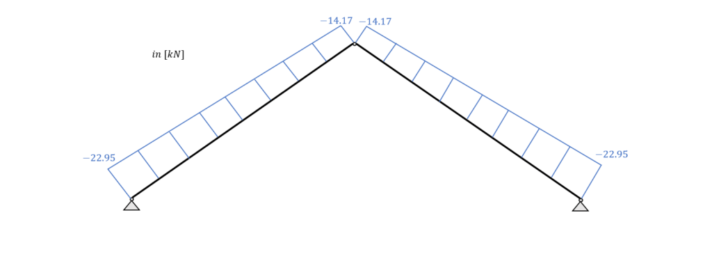
From the picture it can be seen that due to the leading load combination LC3 every element of the rafter system acts in compression.
Bending and Compression Verification – Rafters
From the max. bending moment in the span (10.62 kNm) and the compression force $(\frac{14.17kN + 22.95kN}{2}=18.56kN)$ in the same point we can calculate the stress in the most critical cross section.
| Bending stress: | $\sigma_{m} = \frac{M_{d}}{I_{y}} \cdot \frac{h}{2} = \frac{10.62 kNm}{1.152 \cdot 10^{-4}} \cdot \frac{0.24m}{2} = 11.06 MPa$ |
| Compression stress: | $\sigma_{c} = \frac{N_{d}}{w \cdot h} = \frac{18.56 kN}{0.1m \cdot 0.24m} = 0.773 MPa$ |
| Resistance stresses of the timber material: | $f_{d} = k_{mod} \cdot \frac{f_{k}}{\gamma_{m}}$ |
| Bending resistance stress (M-action): | $k_{mod.M} \cdot \frac{f_{m.k}}{\gamma_{m}} = 14.8 MPa$ |
| Compression resistance stress (M-action): | $k_{mod.M} \cdot \frac{f_{c.k}}{\gamma_{m}} = 12.9 MPa$ |
| Utilization according to EN 1995-1-1 (6.19): | $\eta = (\frac{\sigma_{c}}{f_{c.d}})^2 + \frac{\sigma_{m}}{f_{m.d}} = 0.75 < 1.0$ |
✔️
Bending and Compression is therefore verified.
Shear Verification – Rafters
From the max. shear force (support: 8.21 kN) we can calculate the shear stress in the most critical cross section.
| Shear stress | $\tau_{d} = \frac{3V}{2 \cdot w \cdot h} = \frac{3 \cdot 8.21 kN}{2 \cdot 0.1m \cdot 0.24m} = 0.513 MPa$ |
| Resistance stresses of the timber | $f_{v} = k_{mod.M} \cdot \frac{f_{v}}{\gamma_{m}} = 2.46 MPa$ |
| Utilization according to EN 1995-1-1 (6.13): | $\eta = \frac{\tau_{v}}{f_{v}} = 0.21 < 1.0$ |
✔️
Shear is therefore verified.
Buckling verification – Rafters
We assume that buckling out of the plane (z-direction) can be neglected because the rafters are held on the sides by the roof plates like OSB boards. Therefore we can define the buckling length ly as
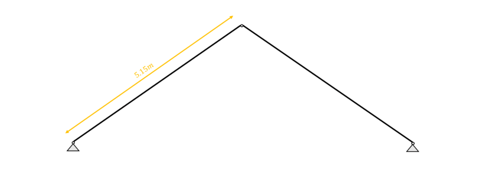
| Moment of inertia | $l_{y} = 5.15m$ |
| Radius of inertia | $i_{y} = \sqrt{\frac{I_{y}}{w \cdot h}} = 0.069m$ |
| Slenderness ratio | $\lambda_{y} = \frac{l_{y}}{i_{y}} = 74.334$ |
| Relative slenderness ratio (EN 1995-1-1 (6.21)) | $ \lambda_{rel.y} = \frac{\lambda_{y}}{\pi} \cdot \sqrt{\frac{f_{c.0.k}}{E_{0.g.05}}} = 1.26$ |
| $\beta_{c}$ factor for solid timber (EN 1995-1-1 (6.29)) | $\beta_{c} = 0.2$ |
| Instability factor (EN 1995-1-1 (6.27)) | $k_{y} = 0.5 \cdot (1+ \beta_{c} \cdot (\lambda_{rel.y} – 0.3) + \lambda_{rel.y}^2) = 1.39$ |
| Buckling reduction coefficient (EN 1995-1-1 (6.25)) | $k_{c.y} = \frac{1}{k_{y} + \sqrt{k_{y}^2 – \lambda_{rel.y}^2}} = 0.51$ |
| Utilization (EN 1995-1-1 (6.23)) | $\frac{\sigma_{c}}{k_{c.y} \cdot f_{c.d}} + \frac{\sigma_{m}}{f_{m.d}} = 0.87 < 1$ |
✔️
Buckling is verified for the rafter.
SLS Design
We also discussed the SLS design a bit more in detail in a previous article. In this blog post we are not explaining too much but rather show the calculations😊
Instantaneous deformation uinst – Rafter roof
The uinst (instantaneous deformation) of our beam is be calculated with the load of the characteristic load combination.
As for the bending moments, shear and axial forces, we are using a FE program to calculate the deflections due to our Load combinations.
LC3 of the characteristic SLS load combinations leads to the largest deflection u.
$$u_{inst} = 15.9 mm$$
EN 1995-1-1 Table 7.2 recommends values for winst only for “Beams on two supports” and “Cantilevering beams” and not for a rafter system like in this case.
However, the limits of the deflection can be agreed upon with the client and the structure is not collapsing due to too large deflections if the rafter is verified for all ULS calculations.
Also, because the bending moment and shear distribution is like one from a simply supported beam, we use the value for “Beam on two supports” from EN 1995-1-1 Table 7.2 in this tutorial.
$w_{inst}$ = l/300 = 5.15m/300 = 17.17 mm
Utilization
$\eta = \frac{u_{inst}}{w_{inst}} = \frac{15.9mm}{17.17mm} = 0.92 < 1$
✔️
The Instantaneous deflection is verified for the rafter(s).
Final deformation ufin
The final deformation ufin (final deformation) of our beam/rafter can be calculated by adding the creep deformation ucreep to the instantaneous deflection uinst.
Therefore, we will calculate the creep deflection with a FE program. This might be a bit quick, but we have already covered the basics in the article about the timber beam dimensioning.
So check that out if you want to know exactly how to calculate ucreep. Let me know in the comments below if you struggle with calculating the creep deformation.
The creep deformation of LC3 is calculated as:
$$u_{creep} = 4.8mm$$
Adding the creep to the instantaneous deflection leads to the final deflection.
$$u_{fin} = u_{inst} + u_{creep} = 15.9mm + 4.8mm= 20.7mm$$
Limit of ufin according to EN 1995-1-1 Table 7.2:
$$w_{fin} = l/150 = 5.15m/150 = 34.3 mm$$
Utilization
$$\eta = \frac{u_{fin}}{w_{fin}} = \frac{20.7mm}{34.3mm} = 0.6$$
✔️
The final deflection is verified for the rafter.
Conclusion
Now that the rafters are verified for compression, bending, buckling and deflection, we can finally say that the cross-section heights and widths are verified – check. ✔️✔️
It is interesting to see the difference in Cross-sectional properties from the rafter to the collar beam roof, right?
We used in both designs the same span and inclination, which results in the rafters being 240 mm high in the rafter system compared to 160 mm in the collar beam system.
But in the collar beam roof there is an additional element – the collar beam.
Now, I am very interested to hear from you: Do you prefer the rafter or the collar beam roof? What are the advantages and disadvantages of both systems? Let us know in the comments below. ✍️✍️

![The Pratt Truss Explained [2026]](https://www.structuralbasics.com/wp-content/uploads/2022/12/Pratt-truss-explained-768x439.jpg)