Shear Wall Design {Step-By-Step Guide}
Shear walls stabilize a building. They resist horizontal loads such as wind and seismic loads and transfer these loads down to the foundation.
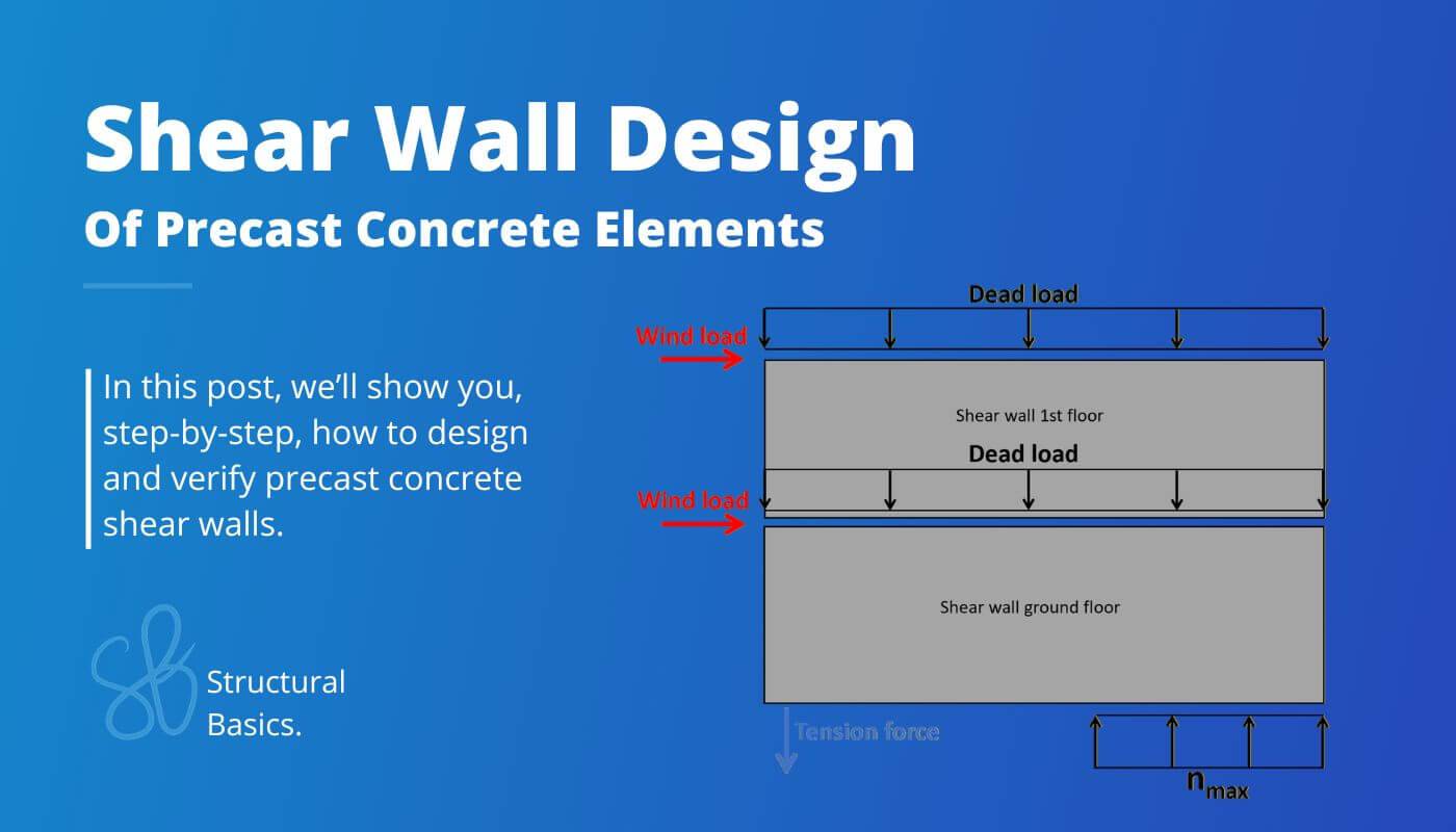
In this guide, we’ll show step-by-step, how you design precast concrete shear walls.
Let’s get started. 🚀🚀
What Are Shear Walls?
Shear walls or also called stabilizing walls are structural elements that resist lateral loads such as wind and seismic loads and transfer these horizontal loads down to the foundation.
Shear walls can be designed as
- Precast concrete (what we use in this blog post)
- In-situ concrete
- Cross-laminated timber
- Masonry
Process of Shear Wall Design
Before we dive into the nerdy calculations, it’s good to get an overview of the steps that need to be taken to design precast concrete shear walls. 👇👇
- Calculate characteristic loads that act on the shear walls
- Load combinations to find the design loads
- Define geometry and material properties of the wall
- ULS tilting verification
- ULS sliding verification
1. Characteristic Loads
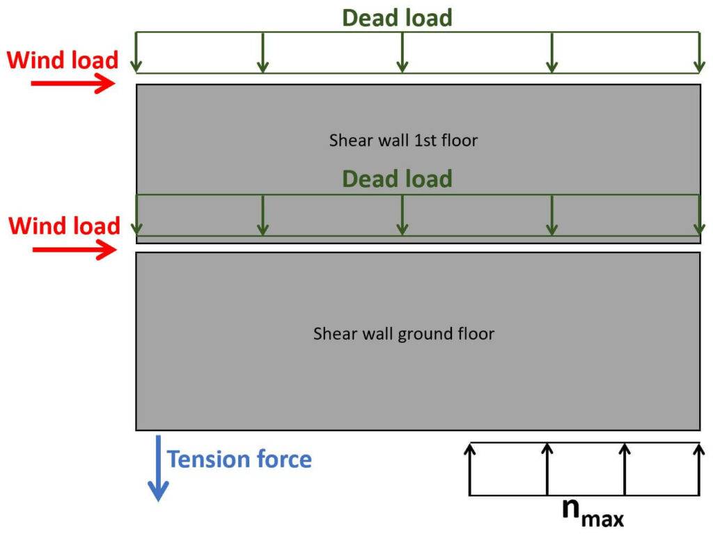
Shear walls have to withstand the horizontal loads acting on a building. However, the self-weight of the structural elements is acting on the walls at the same time, which is beneficial and increasing the resistance of the shear walls.
Therefore, we are also defining the dead load of the structural elements (gk.inf = lower bound).
Lateral Wind Loads
The horizontal loads are transferred from the facades through the floor slabs to the stabilizing walls. The shear walls need to withstand these horizontal wind loads and transfer the loads down to the foundations.
We are not calculating the wind loads in detail in this post, because we have written a step-by-step article that you can follow. 👇👇
Be aware that the following loads are assumptions and we didn’t calculate them.
| Characteristic wind load area D | wk.D = 1 kN/m2 |
| Characteristic wind load area E | wk.D = 0.6 kN/m2 |
The wind loads for areas A, B and C are neglected, because they are of the same magnitude on both transverse facades and therefore don’t influence the stabilizing system for a rectangular building.
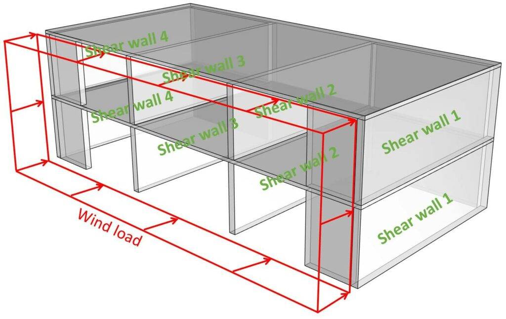
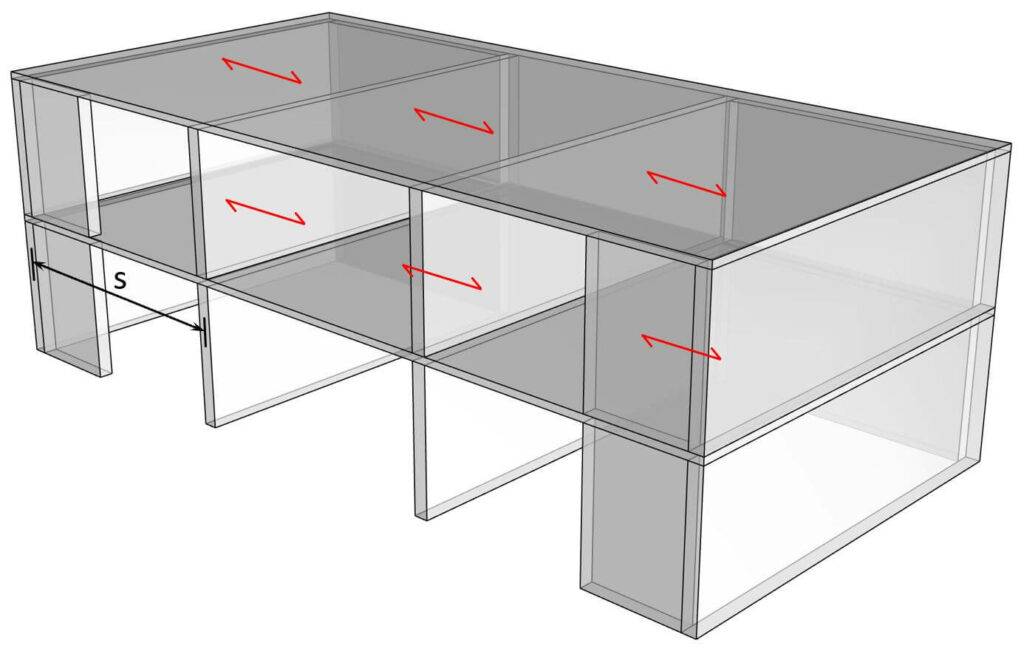
Distribution of Wind Loads
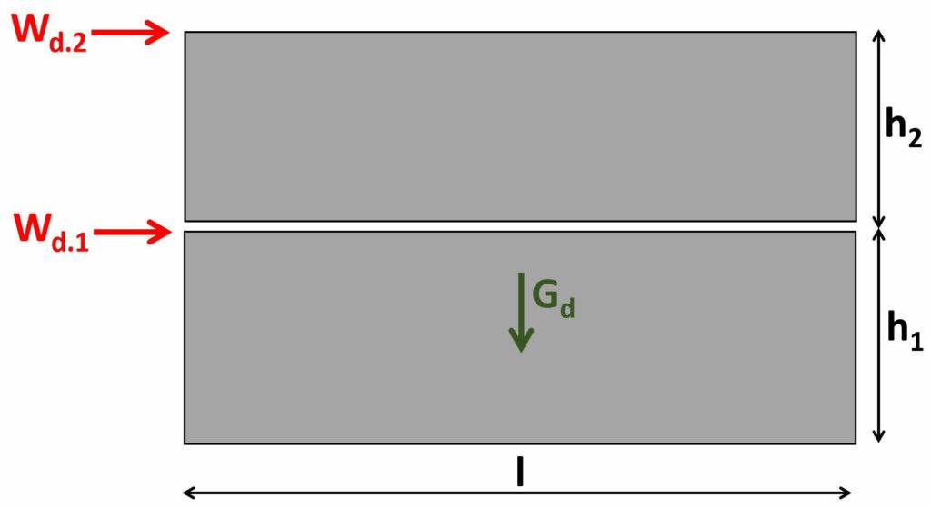
- The horizontal wind loads act perpendicular on the facade (see picture above)
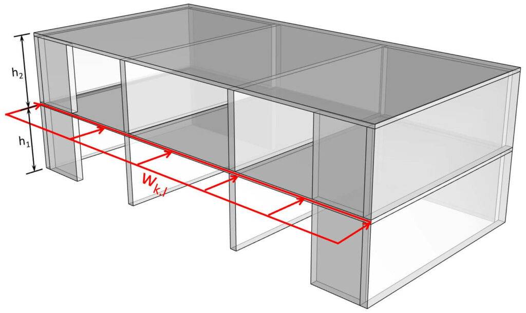
- The facade elements then transfer the load to the floor diaphragms. The load wk.l on the floor diaphragm is calculated as:
$$w_{k.l} = w_k \cdot \frac{h_1 + h_2}{2}$$
Where,
wk = is the wind load (area load)
h1 = height of the storey below the floor
h2 = height of the storey above the floor
Let’s use the following values for h1 and h2:
| h1 | 4 m |
| h2 | 3 m |
We then find the line loads on the floor diaphragms:
| Wind load on roof diaphragm | $w_{w.k.r} = (w_{k.D} + w_{k.E}) \cdot \frac{h_2}{2} = 2.4 kN/m$ |
| Wind load on 1st floor diaphragm | $w_{w.k.1} = (w_{k.D} + w_{k.E}) \cdot \frac{h_1 + h_2}{2} = 5.6 kN/m$ |
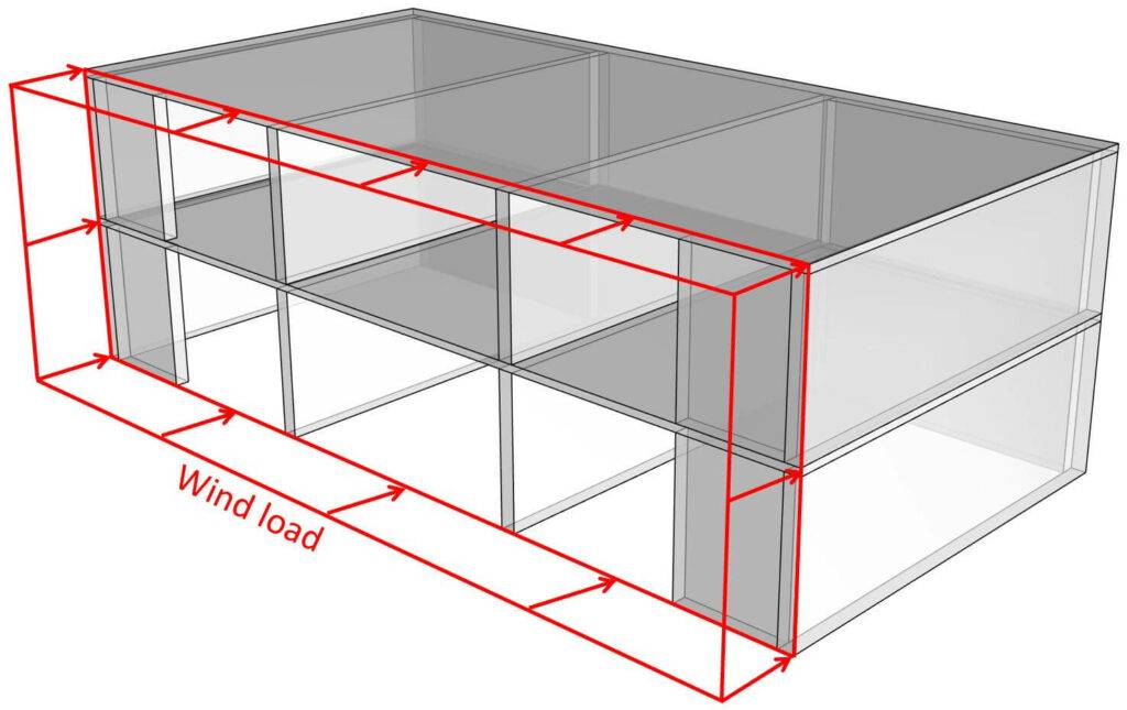
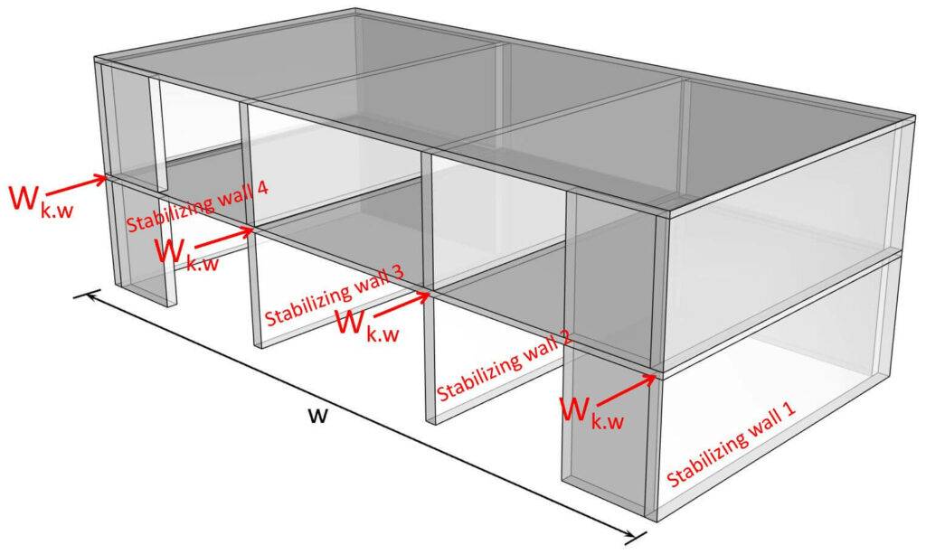
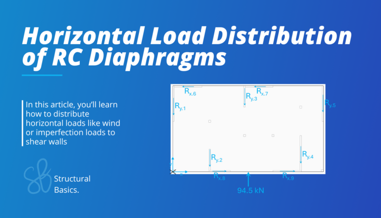
3. The wind loads travel through the floor diaphragm and to the stabilizing walls, assuming the diaphragm is stiff enough. The load distribution can be done either elastically or plastically for in-situ or precast concrete floors. This is, however, a topic for another blog post.
As all 4 transverse stabilizing walls are of the same length and stiffness, each wall takes up 25% of the entire wind load (-> wk.w).
$$w_{k.w} = w_{k.l} \cdot \frac{w}{4}$$
Where,
wk = is the wind load (line load on floor)
w = width of the building
Let’s set the width of the building to: 👇👇
$$w = 15 m$$
Now, this also has to be done for the floor and walls above or in general for every floor and every wall of a building.
| Wind point load on walls – 1st floor | $W_{k.w.1} = w_{k.l.r} \cdot \frac{w}{4} = 9.0 kN$ |
| Wind point load on walls – ground floor | $W_{k.w.0} = w_{k.l.1} \cdot \frac{w}{4} = 21.0 kN$ |
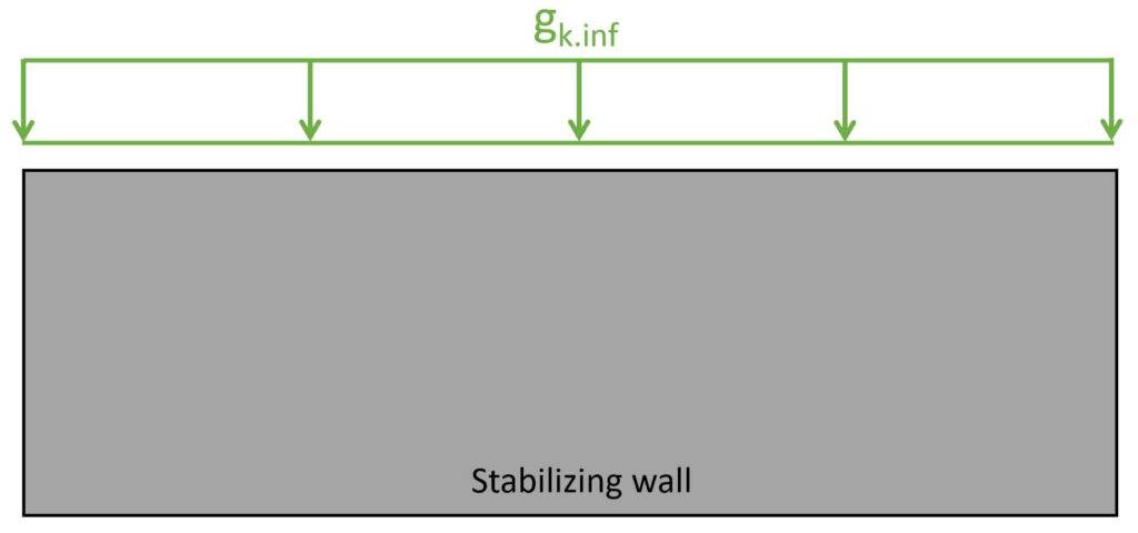
Vertical Dead Load
Additionally, to the horizontal load, the vertical dead load also needs to be considered, as the dead load always acts on the walls.
Later in the calculation, we’ll see that the bigger the dead load, the better the stabilization of the wall.
In our design, the transverse stabilizing walls also support the hollow core slabs.
Therefore, we’ll include the dead load of the stabilizing walls itself and the hollow core slabs.
| Dead load of hollow core slab (t=220 mm) | $g_{k.h} = 3.24 kN/m^2$ |
| Density of concrete of wall | $\rho_c = 25 kN/m^3$ |
| Thickness of walls | $t = 180 mm$ |
| Dead load on stabilizing wall (2 and 3) – 1st floor | $g_{k.inf.1} = \rho_c \cdot t \cdot h_2 + g_{k.h} \cdot \frac{5m + 5m}{2} = 29.7 kN/m$ |
| Dead load on stabilizing wall (2 and 3) – ground floor | $g_{k.inf.0} = \rho_c \cdot t \cdot h_1 + g_{k.h} \cdot \frac{5m + 5m}{2} = 34.2 kN/m$ |
2. Load Combinations
Load combinations combine several load cases and multiply the characteristic loads with safety factors.
Luckily, we have already written an extensive article about what load combinations are and how we use them.
In case you need to brush up on it or want to check how we derived the safety factors, you can read the blog post here.
The dead load will not have the typical factor of 1.35 but instead 1.0 according to EN 1990 Table A1.2 (B). This is because the dead load acts favourable, which means that the bigger the dead load, the higher the load bearing capacity.
For the design of the stabilizing wall, we’ll look at the following ULS load combinations. 👇👇
ULS load combinations
| LC1 | $1.0 \cdot g_{k.inf} + 1.5 \cdot w_k$ | |
| LC2 | $1.35 \cdot g_{k.sup} + 1.5 \cdot w_k + 1.5 \cdot \psi_0 \cdot q_k$ |
Now, LC1 will be leading for the verification of the stabilizing wall. That’s why, we’ll continue only with LC1. However, LC2 will lead to compression stresses at the bottom of the walls. So to verify the joint, you should also consider LC2.
| Design wind load – 1st floor | $W_{d.w.1} = 1.5 \cdot W_{k.w.1} = 13.5 kN$ |
| Design wind load – ground floor | $W_{d.w.0} = 1.5 \cdot W_{k.w.0} = 31.5 kN$ |
| Design dead load – 1st floor | $g_{d.inf.1} = 1.0 \cdot g_{k.inf.1} = 29.7 kN/m$ |
| Design dead load – ground floor | $g_{d.inf.0} = 1.0 \cdot g_{k.inf.0} = 34.2 kN/m$ |
3. Geometry Of The Walls
We have already defined the heights of the stabilizing walls as h2 and h1.
We set the length to l = 5m.
4. Concrete and Reinforcement Properties
| Concrete compression strength of joint | $f_{c.k} = 20 MPa$ |
| Partial factor in-situ concrete (Denmark) | $\gamma_c = 1.45$ |
| Design concrete compression strength (joint) | $f_{c.d} = 13.79 MPa$ |
| Reinforcement yield strength | $f_{y.k} = 550 MPa$ |
| Partial factor reinforcement (Denmark) | $\gamma_s = 1.2$ |
| Design yield strength | $f_{y.d} = \frac{f_{y.k}}{\gamma_s} = 458.3 MPa$ |
5. ULS Design of Stabilizing Walls
In the ULS design of stabilizing walls, we verify tilting and sliding.
Tilting – Is vertical reinforcement required?
First, we’ll check if the wall is stable without vertical reinforcement. The reinforcement would anchor the wall to the wall below or the foundation.
Now, in the following we verify only the bottom wall as this is the most critical. However, in your structural documentation, you should verify each wall on each floor.
| Vertical design load (point load) | $G_d = (g_{d.inf.1} + g_{d.inf.0}) \cdot l = 319 kN$ |
| Design moment due to horizontal loads – ground floor | $M_{d.0} = W_{d.2} \cdot (h_2 +h_1) + W_{d.1} \cdot h_1 = 220.5 kNm$ |
| Eccentricity of load | $e = \frac{M_{d.0}}{G_d} = 0.69m$ |
| Width of compression zone | $c = 2 \cdot (\frac{l}{2} – e) = 3.62m$ |
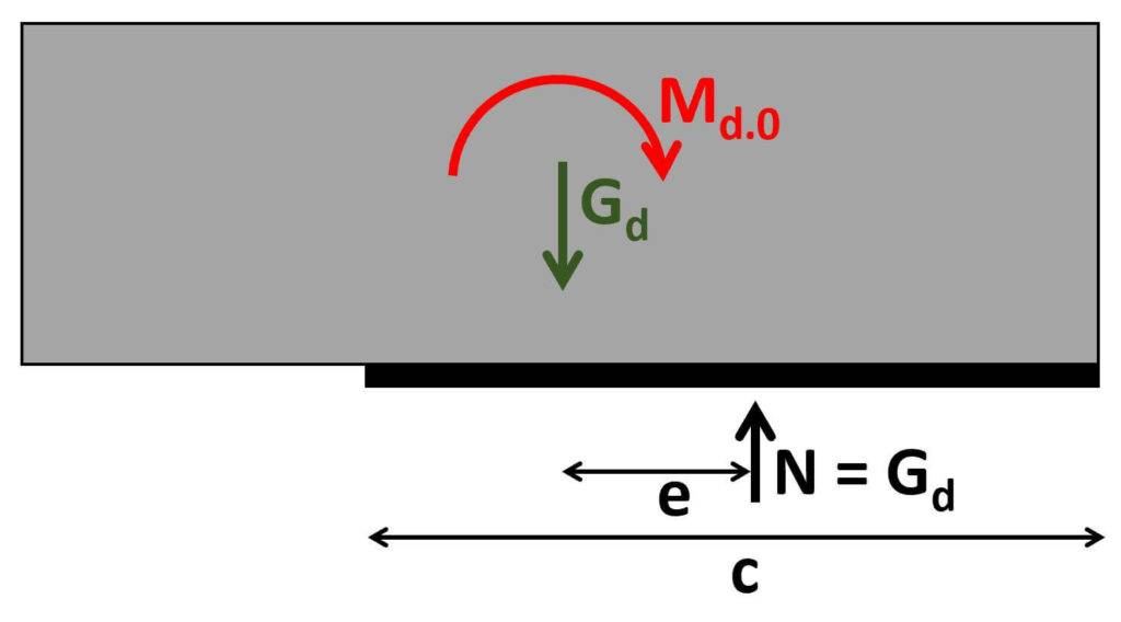
In the verification, we are basically checking that the eccentricity of the load due to the moment is not outside the wall and that the joint can resist the compression stresses in the compression zone.
The loads can only be transferred through an effective section of the joint. This section is smaller than the thickness of the wall, because the hollow core slabs are supported on both sides, and these slabs can’t take any vertical loading.
Now, on the ground floor, we could use the full width of the wall. However, in this blog post we want to showcase how you use the effective thickness and furthermore using the effective width is conservative.
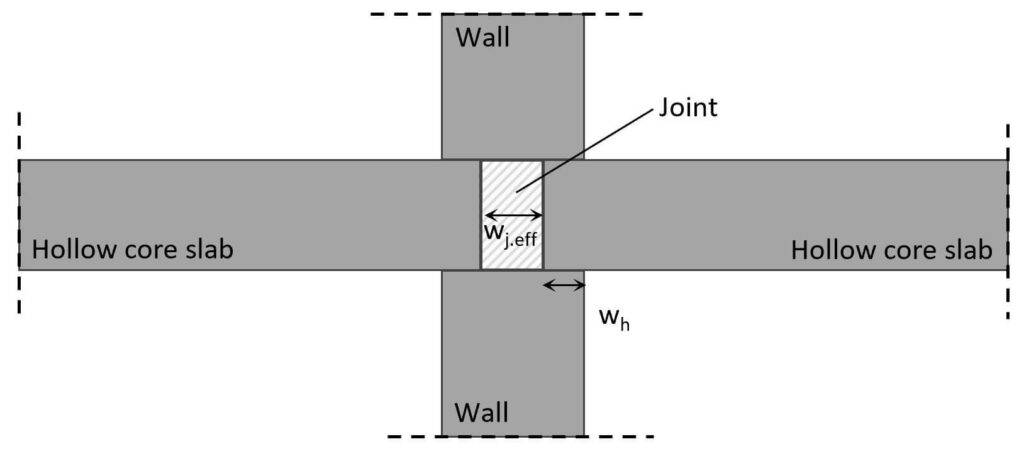
| Support width of hollow core slab (check with your manufacturer) | $w_{h} = 65mm$ |
| Effective width of section | $w_{j.eff} = t-2 \cdot w_h =70mm$ |
| Vertical load bearing capacity of the joint | $n_{max} = f_{c.d} \cdot w_{j.eff} = 965.5 kN/m$ |
| Check 1 if vertical reinforcement is required | $e < \frac{l}{2} = 1$ -> Verified |
| Check 2 if vertical reinforcement is required | $G_d < c \cdot n_{max} = 1$ -> Verified |
As both requirements are fulfilled, we don’t have to add vertical reinforcement.
Tilting – Vertical reinforcement required
Now, let’s look also at a situation where we need vertical reinforcement.
We therefore increase the horizontal loads.
| Design wind load – level 2 | $W_{d.2} = 70 kN$ |
| Design wind load – level 1 | $W_{d.1} = 80 kN$ |
| Moment due to horizontal load – ground floor | $M_{d.0} = W_{d.2} \cdot (h_2 +h_1) + W_{d.1} \cdot h_1 = 810 kNm$ |
| Eccentricity of load | $e = \frac{M_{d.0}}{G_d} = 2.54m$ -> load outside of wall |
| Width of compression zone | $c = 2 \cdot (\frac{l}{2} – e) = -0.07m$ -> load outside of wall |
| Check 1 if vertical reinforcement is required | $e < \frac{l}{2} = 0$ -> Not verified |
| Check 2 if vertical reinforcement is required | $G_d < c \cdot n_{max} = 0$ -> Not verified |
Both requirements are not fullfilled. Therefore, we need vertical reinforcement.
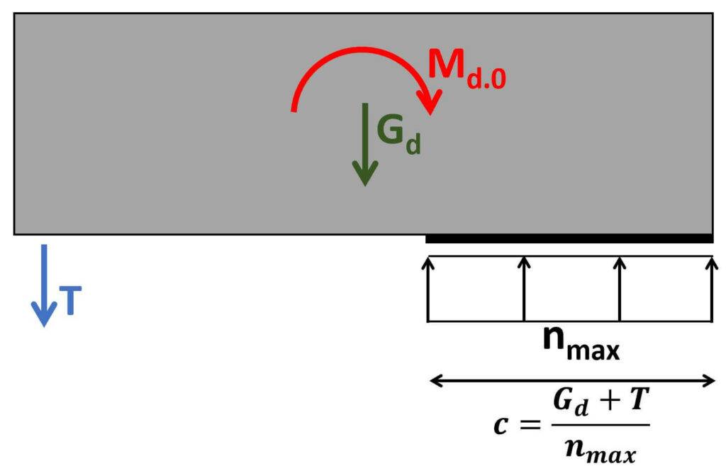
We’ll place it 0.3m from the wall edge.
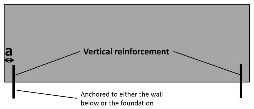
Here are some details of how the rebar anchorage looks like.
| Egde distance vertical reinforcement | $a = 0.3 m$ |
| Tension force | $T = -(G_d – l \cdot n_{max} + a \cdot n_{max}) – \sqrt{(G_d – l \cdot n_{max} + a \cdot n_{max})^2 – (2n_{max} \cdot M_{d.0} – l \cdot n_{max} \cdot G_d + G_d^2)} = 14.7 kN$ |
Lastly, we’ll calculate the reinforcement required to resist this tension force.
| Diameter of reinforcement | $d = 10mm$ |
| Tensile capacity of rebar | $F_{Rd} = (\frac{d}{2})^2 \cdot \pi \cdot f_{y.d} = 36 kN$ |
| Utilization | $\eta = \frac{T}{F_{Rd}} = 0.41$ |
Sliding
Sliding is the other verification that we need to check. From my experience sliding is usually not the critical verification.
Sliding becomes the critical verification for very long walls which are exposed with high horizontal loads and small vertical loads.
For sliding, we check that the shear force at the element base is smaller than the shear resistance of the joint.
| Friction coefficient | $\mu = 0.5$ |
| Shear force at element base | $V_d = W_{d.2} + W_{d.1} = 150 kN$ |
| Shear resistance of element base | $V_{Rd} = \mu \cdot (G_d + T) = 167.1 kN$ |
| Utilization | $\eta = \frac{V_d}{V_{Rd}} = 0.9$ |
Sliding is also verified. ✅✅
In case sliding doesn’t verify, the vertical reinforcement that isn’t used for tilting (at the other end of the element) can be used to resist the shear force.
As a rule of thumb, the resistance of the anchorage perpendicular to its centerline is half of the tensile capacity:
$$V_{Rd} = \frac{F_{Rd}}{2}$$
Conclusion
Et voila, the precast concrete stabilizing wall is verified and dimensioned. 💯💯
If you are new to structural design, then check out more of our design tutorials where you can learn how to design elements such as: 👇👇
But now, I would like to hear from you: Are you designing stabilizing walls for a uni project? Or are you renovating your own house? Tell us a bit about the structure, as we all want to learn from each other.✍️
![Pad Foundation In Clay [Design Of Soil And Concrete]](https://www.structuralbasics.com/wp-content/uploads/2023/05/Pad-foundation-design-clay-768x439.jpg)