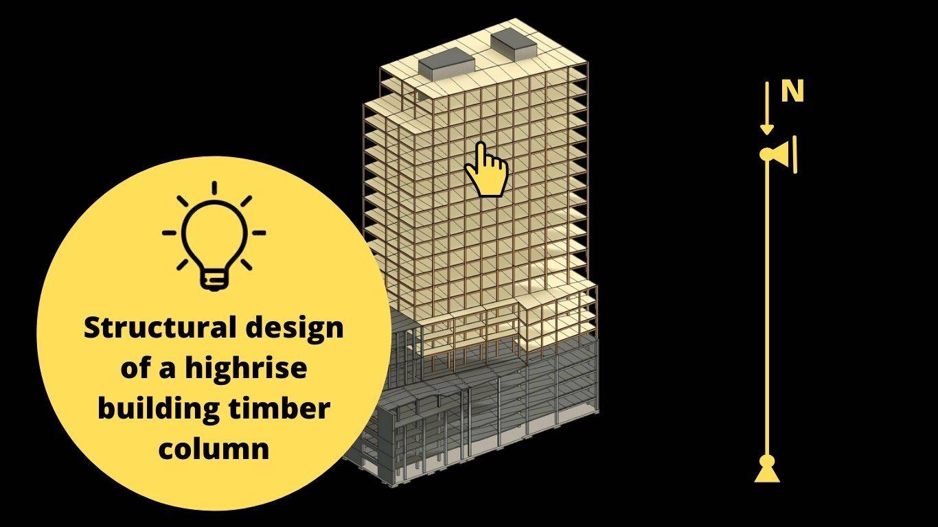
Timber column design: An example of a highrise building column
After designing some roof elements like rafters, purlins and beams, it is now time to look at structural timber columns.
Some of the concepts of designing timber elements have been mentioned in previous articles.
Therefore, we will not go too much into detail if explained previously but will provide a link, so you can read up on it📖.
Alright, so when we say we want to design a timber column, what do we mean by that?🤔
A structural column is an element that is mostly vertical, and the biggest load it has to resist is – in most cases – the axial load. Bending moments can act in columns if imperfections or/and horizontal loads such as wind loads are applied or the column is part of a frame with moment stiff connections.
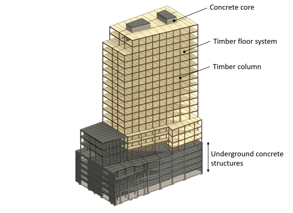
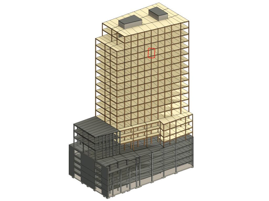
The following picture shows an example where a timber column is used in a high-rise building.
So let’s have a look at what we are going to cover in this blog post👀
1. Choose a right statical system, column in our case
2. Calculate all characteristic loads (dead, snow, wind, live load, etc.)
3. Calculate all load combinations
4. Choose a timber material and find material properties
5. Assume the width w and height h of the cross-section
6. Verify the beam for compression. If not verified, increase the width or height of the beam and do the calculation again
7. Verify the beam for buckling. If not verified, increase the width or height of the beam and do the calculation again
8. If all of those checks are now verified, then you have figured out the correct dimensions of the column
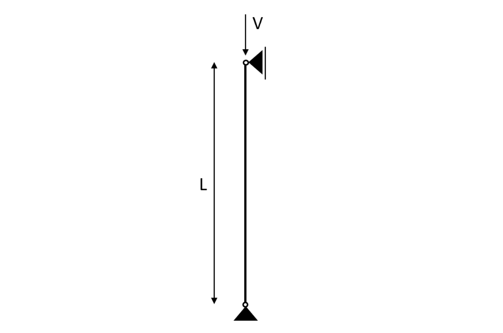
Statical system
The column itself is a beam which means that other than axial loads or also called normal forces (Tension + Compression) it can also take bending moments.
Basically, it is a beam turned by 90°.
As we like to keep things as close to reality and in context as possible this column can be a column in a timber highrise building, a timber roof structure, etc.
Loads
While we have gone into detail with how loads are travelling through elements and then can be applied to other elements in other articles, we are not doing this in full scale for this column calculation.
That being said, let’s have a quick look how certain loads travel to the column of “our” high-rise building, and then we can make some assumptions for the value of the loads.
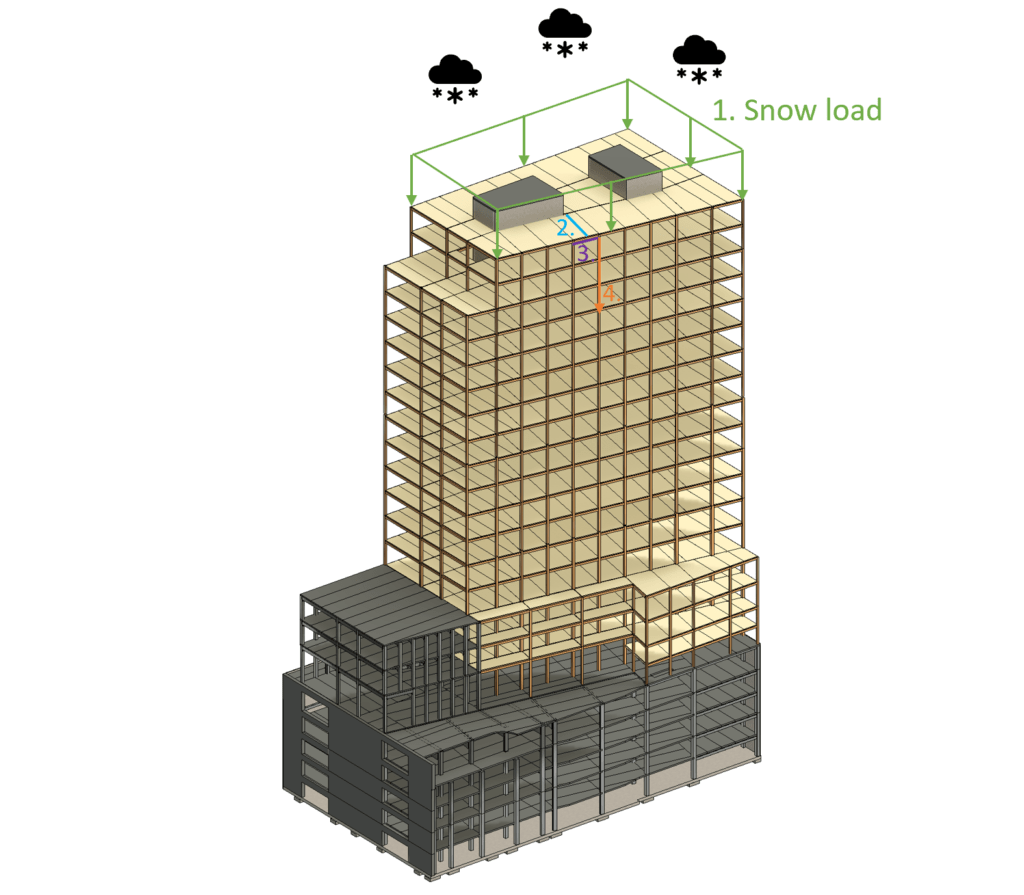
Loadpath of snow load to column – Highrise
- The snowload (area load) is applied vertically downwards on the roof
- The snowload travels from the deck elements to the beams
- From the beams the snow load is traveling to the timber columns and concrete core
- The snow load travels vertically from column to column
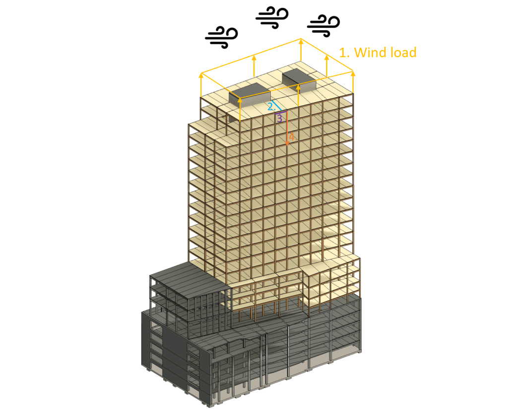
Loadpath of wind load to column – Highrise
- The wind load (area load) is applied vertically upwards on the roof.
- The wind load is taken by the deck elements. The wind leads to uplift.
- From the beams the wind load is traveling to the timber columns and concrete core
- The wind load travels vertically and in tension from column to column
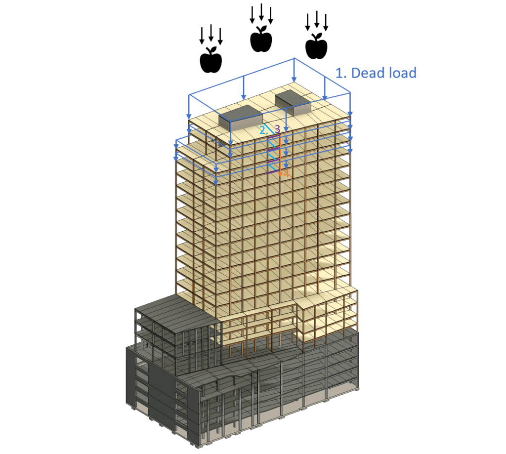
Loadpath of dead load to timber column – Highrise
The dead load on the roof is applied in the same way as the snow load and also travels on the same path to the column.
But the dead load from the other floors also need to be taken into account.
- The dead load (area load) is applied vertically downwards on the roof and the floor slabs
- The dead load travels from the deck elements to the beams
- From the beams the dead load travels to the timber columns and concrete core
- The dead load travels vertically from column to column
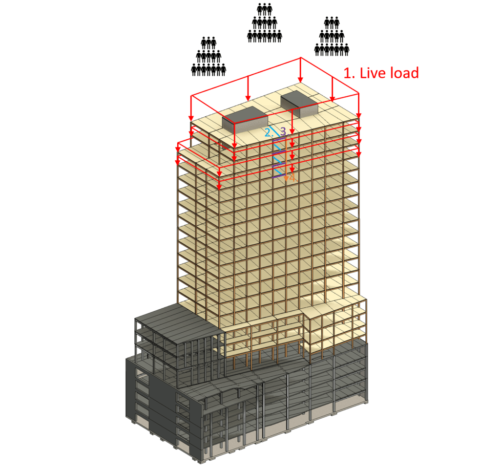
Loadpath of live load to column – Highrise
The live load on the roof is applied in the same way as the snow load and also travels on the same path to the column.
But the live load from the other floors also need to be taken into account.
- The live load (area load) is applied vertically downwards on the roof and the floor slabs
- The live load travels from the deck elements to the beams
- From the beams, the live load travels to the timber columns and concrete core
- The live load travels vertically from column to column
Assumption of loads
As already mentioned at the beginning of this section, we are not going to derive the values of the loads because this tutorial is about the design of the column.
| Characteristic snow load | 8.8 kN |
| Characteristic wind load | -9.1 kN |
| Characteristic dead load | 93 kN |
| Characteristic live load | 110 kN |
Load combinations
Luckily, we have already written an extensive article about what load combinations are and how we use them. In case you need to brush up on it, you can read the blog post here.
ULS Load combinations – Highrise Column
| LC1 | $1.35 * 93 kN $ | $125.55 kN$ |
| LC2 | $1.35 * 93 kN + 1.5 * 110 kN $ | $290.55 kN $ |
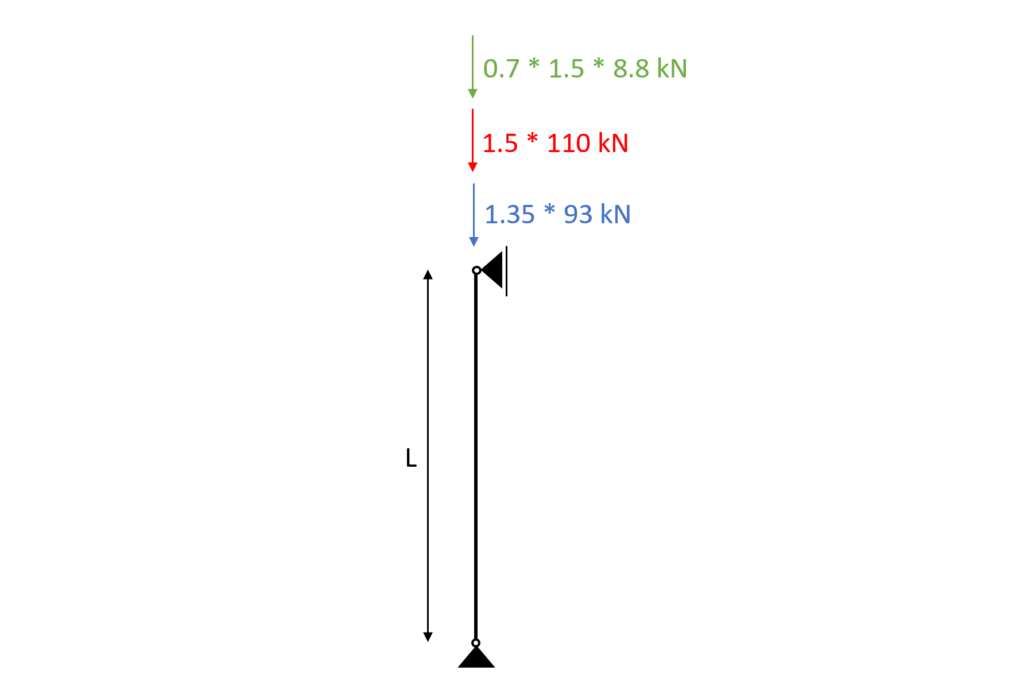
| LC3 | $1.35 * 93 kN + 1.5 * 110 kN + 0.7 * 1.5 * 8.8 kN$ | $299.79 kN$ |
| LC4 | $1.35 * 93 kN + 0 * 1.5 * 110 kN + 1.5 * 8.8 kN$ | $138.75 kN $ |
| LC5 | $1.35 * 93 kN + 1.5 * 110 kN + 0.7 * 1.5 * 8.8 kN + 0.6 * 1.5 * (-9.1 kN) $ | $291.6 kN$ |
| LC6 | $1.35 * 93 kN + 0 * 1.5 * 110 kN + 1.5 * 8.8 kN + 0.6 * 1.5 * (-9.1 kN) $ | $130.56 kN $ |
| LC7 | $1.35 * 93 kN + 0 * 1.5 * 110 kN + 0.7 * 1.5 * 8.8 kN + 1.5 * (-9.1 kN) $ | $ 121.14 kN $ |
| LC8 | $1.35 * 93 kN + 1.5 * 8.8 kN $ | $ 138.75 kN $ |
| LC9 | $1.35 * 93 kN + 1.5 * (-9.1 kN) $ | $ 111.9 kN $ |
| LC10 | $1.35 * 93 kN + 1.5 * 8.8 kN + 0.6 * 1.5 * (-9.1 kN) $ | $ 130.56 kN $ |
| LC11 | $1.35 * 93 kN + 1.5 * (-9.1 kN) + 0.7 * 1.5 * 8.8 kN $ | $121.14 kN$ |
| LC12 | $1.35 * 93 kN + 1.5 * 110 kN + 0.6 * 1.5 * (-9.1 kN)$ | $282.36 kN$ |
So for example Load combination 3 (LC3) can be visualized as in the next figure.
Column timber material
For this blog post/tutorial, we are choosing a Glulam GL 30h.
More comments on which timber material to pick and where to get the properties from were made here.
The following characteristic strength and stiffness parameters were found online from a manufacturer.
| Bending strength $f_{m.k}$ | 30 $\frac{N}{mm^2}$ |
| Tension strength parallel to grain $f_{t.0.k}$ | 24 $\frac{N}{mm^2}$ |
| Tension strength perpendicular to grain $f_{t.90.k}$ | 0.5 $\frac{N}{mm^2}$ |
| Compression strength parallel to grain $f_{c.0.k}$ | 30 $\frac{N}{mm^2}$ |
| Compression strength perpendicular to grain $f_{c.90.k}$ | 2.5 $\frac{N}{mm^2}$ |
| Shear strength $f_{v.k}$ | 3.5 $\frac{N}{mm^2}$ |
| E-modulus $E_{0.mean}$ | 13.6 $\frac{kN}{mm^2}$ |
| E-modulus $E_{0.g.05}$ | 11.3 $\frac{kN}{mm^2}$ |
Modification factor $k_{mod}$
If you do not know what the modification factor $k_{mod}$ is, we wrote an explanation to it in a previous article, which you can check out.
Since we want to keep everything as short as possible, we are not going to repeat it in this article – we are only defining the values of $k_{mod}$.
For the high-rise building which is classified as Service class 1 according to EN 1995-1-1 2.3.1.3 we extract the following load durations for the different loads.
| Self-weight/dead load | Permanent |
| Live load, Snow load | Medium-term |
| Wind load | Instantaneous |
From EN 1995-1-1 Table 3.1 we get the $k_{mod} values for the load durations and a Glulam GL 30h (Solid timber).
| Self-weight/dead load | Permanent action | Service class 1 | 0.6 |
| Live load, Snow load | Medium term action | Service class 1 | 0.8 |
| Wind load | Instantaneous action | Service class 1 | 1.1 |
Partial Factor $\gamma_{M}$
According to EN 1995-1-1 Table 2.3 the partial factor $\gamma_{M}$ is defined as
$\gamma_{M} = 1.25$
Assumption of width and height of column
We are defining the width w and height h of the Gl 30h Cross-section as
Width w = 160 mm
Height h = 180 mm
Those values are first estimates based on the experience of the designer.
Now with those dimensions the Moment of inertias in y and z direction can be calculated as
$I_{y} = \frac{w * h^3}{12} = \frac{160mm * (180mm)^3}{12} = 7.78 * 10^7 mm^4 $
$I_{z} = \frac{w^3 * h}{12} = \frac{(160mm)^3 * 180mm}{12} = 6.14 * 10^7 mm^4 $
ULS Design
In the ULS (ultimate limit state) Design we verify the stresses in the timber members due to compression and buckling.
To calculate the stresses, we first need to know for which load we do the verification.
Usually, you can apply all characteristic loads in your FE program, which then calculates all load combinations automatically.
But since we are doing hand calculations in this tutorial, we will pick the most critical load combination.
Since LC2, LC3, LC5 and LC12 lead all to roughly the same design load and have the live load as the leading imposed load, we pick LC3 as the design load.
$N_{d} = 299.79 kN$
Compression Verification – Timber column
The compressive stresses in the column are calculated as
$\sigma_{c.d} = \frac{N_{d}}{w \cdot h} = \frac{299.79 kN}{160mm \cdot 180mm} = 10.41 MPa $
The design compressive strength for LC3 (Medium – term) is calculated as
$f_{c.d} = k_{mod.m} \cdot \frac{f_{c.0.k}}{\gamma_{M}} = 19.2 MPa$
The Verification compression parallel to the grain is done according to EN 1995-1-1 (6.2)
$\eta = \frac{\sigma_{c.d}}{f_{c.d}} = \frac{10.41 MPa}{19.2 MPa} = 0.54$
Buckling Verification – Timber column
At first we are defining the buckling lengths. The column is simply supported and also supported out of plane by beams. Therefore the buckling lengths are defined as the length of the column.
$l_{y} = 3.0m$ and $l_{z} = 3.0m$
Radius of inertia
$i_{y} = \sqrt{\frac{I_{y}}{w*h}} = 0.052m$
$i_{z} = \sqrt{\frac{I_{z}}{w*h}} = 0.046m$
Slenderness ratio
$\lambda_{y} = \frac{l_{y}}{i_{y}} = 57.735$
$\lambda_{z} = \frac{l_{z}}{i_{z}} = 64.952$
Relative slenderness ratio (EN 1995-1-1 (6.21))
$ \lambda_{rel.y} = \frac{\lambda_{y}}{\pi} * \sqrt{\frac{f_{c.0.k}}{E_{0.g.05}}} = 0.95$
$ \lambda_{rel.z} = \frac{\lambda_{z}}{\pi} * \sqrt{\frac{f_{c.0.k}}{E_{0.g.05}}} = 1.065$
$\beta_{c}$ factor for solid timber (EN 1995-1-1 (6.29))
$\beta_{c} = 0.2$
Instability factor (EN 1995-1-1 (6.27))
$k_{y} = 0.5 * (1+ \beta_{c} *(\lambda_{rel.y} – 0.3) + \lambda_{rel.y}^2) = 1.013$
$k_{z} = 0.5 * (1+ \beta_{c} *(\lambda_{rel.z} – 0.3) + \lambda_{rel.z}^2) = 1.144$
Buckling reduction coefficient (EN 1995-1-1 (6.25))
$k_{c.y} = \frac{1}{k_{y} + \sqrt{k_{y}^2 – \lambda_{rel.y}^2}} = 0.728$
$k_{c.z} = \frac{1}{k_{z} + \sqrt{k_{z}^2 – \lambda_{rel.z}^2}} = 0.641$
Utilization in plane (EN 1995-1-1 (6.23))
$\frac{\sigma_{c}}{k_{c.y} * f_{c.d}} = 0.74$
Utilization out of plane (EN 1995-1-1 (6.24))
$\frac{\sigma_{c}}{k_{c.z} * f_{c.d}} = 0.85$
![Butt Weld Design [Structural Calculation]](https://www.structuralbasics.com/wp-content/uploads/2023/09/Butt-weld-design-768x439.jpg)
![How To Dimension Rafters Of Purlin Roofs? [Structural Guide]](https://www.structuralbasics.com/wp-content/uploads/2022/03/How-to-design-rafters-of-purlin-roofs-768x439.jpg)
![Timber Truss Roof Design [A Structural Guide]](https://www.structuralbasics.com/wp-content/uploads/2022/04/Timber-Truss-Roof-Design-768x439.jpg)