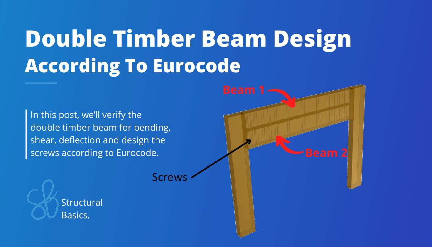
Double Timber Beam Design {A Step-By-Step Guide}
Renovation projects sometimes demand special structural designs. In this post, we’ll discuss one of these special solutions – double timber beams. 🪵🪵
This structural system is useful in case the loads increased due to a changed usage of the floor above and the existing beam needs to be strengthened.
In this post, we’ll design a double timber beam, step-by-step.
Let’s get started. 🚀🚀
Process of Double Timber Beam Design
Before we dive into the nerdy calculations, it’s good to get an overview of the steps that need to be taken to design a double beam. 👇👇
- Calculate characteristic loads that act on the beam
- Load combinations
- Define properties of timber beams and connectors
- ULS bending verification
- ULS shear verification
- ULS Connection design
- SLS Deflection verification
Static System of Double Beam
There is a variety of different static systems that the structural engineer can choose from.
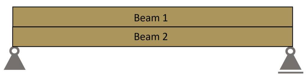
However, for timber structures simply supported beams are most common.
Simply Supported Beam
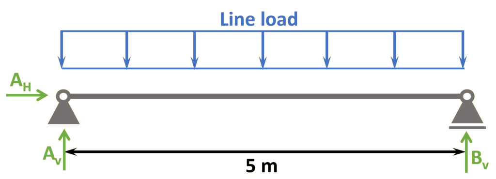
Support types
Roller & Pin
Reactions
Roller: Vertical
Pin: Vercial & Horizontal
Characteristic Loads on RC Beam
The loads of a structure depend on its location, geometry, building type and other factors.
We’ll assume in this tutorial that we design the beam of 2 storey building where the beam carries some of the load of the floor above. 🏠🏠
In this simplified design guide, the following vertical loads are considered:
Load transfer
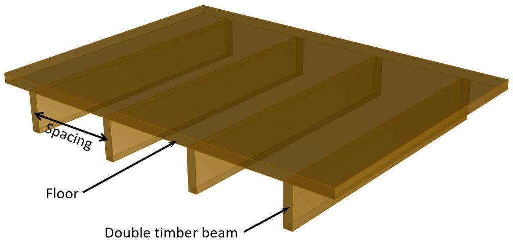
- Live and dead load (self-weight of the floor) are applied as area loads [kN/m2] on the timber floor.
The floor is supported by the double timber beams. - By multiplying the area loads (live and dead load) with the spacing of the beams, line loads are calculated. These line load can now be applied to the beams.
$$Area load \cdot spacing = Line load$$
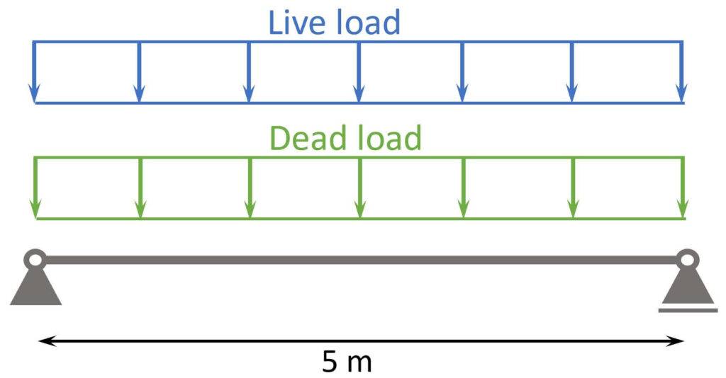
The following characteristic load values are assumptions.
| $g_{k}$ | 2 kN/m | Characteristic value of dead load |
| $q_{k}$ | 1.5 kN/m | Characteristic value of live load |
❗
The characteristic values of loads depend on a lot of different factors like location, National Annex and usage of the building to name just a few. Loads therefore need to be calculated for every structure.
Load combinations
Load combinations combine several load cases and multiply the characteristic loads with safety factors.
Luckily, we have already written an extensive article about what load combinations are and how we use them.
In case you need to brush up on it or want to check how we derived the safety factors, you can read the blog post here.
ULS load combinations
| LC1 | $1.35 \cdot 2.0 kN/m $ | $2.7 kN/m$ | |
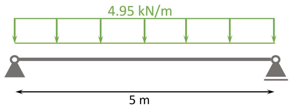
| LC2 | $1.35 \cdot 2.0 kN/m + 1.5 \cdot 1.5 kN/m$ | $4.95 kN/m$ |
You can also use our load combination generator, which creates the load combinations automatically for you, and you can copy & paste the table into Word. 🔥🔥
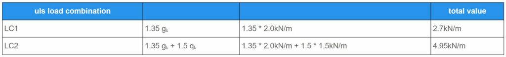
So the design line load we are designing the double beam and its connections for is:
$$p_d = 4.95 kN/m$$
SLS characteristic load combination
The characteristic load combination is used for the deflection verification.
| LC1 | $2.0 kN/m + \cdot 1.5 kN/m$ | $3.5 kN/m$ |
Geometry Of The Beam
Here are the geometrical properties of 1 of the 2 timber beams. 👇👇
| Width | $w=0.165 m$ |
| Height | $h=0.166 m$ |
| Span | $l = 5 m$ |
| Moment of inertia (beams acting together) | $I_y = \frac{(2 \cdot h)^3 \cdot w}{12} = 50317.3 cm^4$ |
Timber and Screw Properties
We’ll use glulam GL28h for the timber beams and a full threaded screw with cylindrical head from Rothoblaas.
But the double beams can be calculated with any timber material and different screws.
Here are the material properties we are going to use.
| Bending strength (GL28h) | $f_{m.k}= 28 N/mm^2$ |
| Shear strength (GL28h) | $f_{v.k}= 3.5 N/mm^2$ |
| E-modulus (GL28h) | $E_{0.mean} = 12.6 kN/mm^2$ |
| Density (GL28h) | $\rho_{k} = 425 \frac{kg}{m^3}$ |
| Partial factor (Denmark) | $\gamma_m = 1.3$ |
| Modification factor | $k_{mod} = 0.8$ |
| Screw diameter (Rothoblaas VGZ EVO) | $d = 7mm$ |
| Screw head diameter | $d_h = 9.5mm$ |
| Screw length | $l_{screw} = 300mm$ |
| Characteristic withdrawal parameter (Rothoblaas datasheet) | $f_{ax.k} = 11.7 N/mm^2$ |
| Characteristic head pull-through parameter (ETA-11/0030) | $f_{head.k} = 20 N/mm^2$ |
| Yield moment (Rothoblaas datasheet) | $M_{y.k} = 14.2 Nm$ |
Now, we are all set to design the beam(s) and connections. 🔥🔥
Internal Forces
We need to calculate the max. bending moment and shear force for our governing ULS load.
The bending moments and shear forces are the same for beams acting together or not, because the
moment of inertia and stiffness does not have an influence on the internal forces of statically determinate structures.
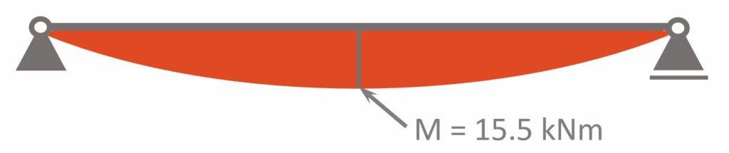
ULS Max bending moment
$$M_d = 4.95 kN/m \cdot \frac{l^2}{8} = 15.5 kNm$$
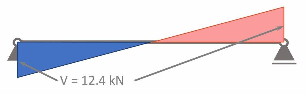
ULS Max shear force
$$V_d = 1/2 \cdot 4.95 kN/m \cdot l = 12.4 kN$$
ULS Bending Moment Verification
In the ULS (ultimate limit state) bending verification we verify that the bending design stresses are smaller than the resistance stresses of the timber material.
We assume that the connection between the 2 beams is stiff enough and transfers all shear stresses from one beam to the other. Therefore we use the full cross-section consisting of both beams.
Bending stress:
$$\sigma_m = \frac{M_d}{I_y} \cdot \frac{2h}{2} = 5.1 MPa$$
Bending design resistance:
$$f_{m.d} = k_{mod} \cdot \frac{f_{m.k}}{\gamma_m} = 17.2 MPa$$
Utilization (EN 1995-1-1 (6.11)):
$$\eta = \frac{\sigma_m}{f_{m.d}} = 0.3 < 1.0$$
Verification fullfilled!
ULS Shear Verification
We verify the shear of the timber beam(s) according to EN 1995-1-1 6.1.7.
Shear stress:
$$\tau_v = \frac{3}{2} \cdot \frac{V_{Ed}}{w \cdot 2h} = 0.34 MPa$$
Shear design resistance:
$$f_{v.d} = k_{mod} \cdot \frac{f_{v.k}}{\gamma_m} = 2.2 MPa$$
Utilization (EN 1995-1-1 (6.13)):
$$\eta = \frac{\tau_v}{f_{v.d}} = 0.16 < 1.0$$
Verification fullfilled!
Connection Design
In this section we design how many screws are needed that all of the shear is transferred from one beam to another and our assumption of 1 cross-section consisting of the 2 beams is corrrect.
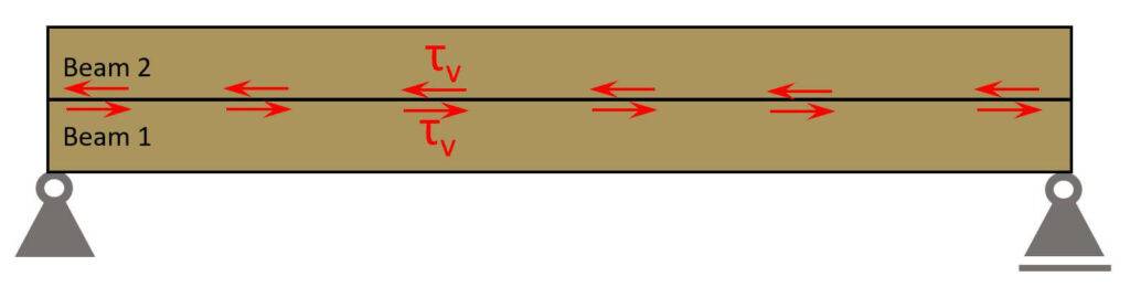
The shear stresses on one side of an infinitesimal element are of the same magnitude as the shear stresses on the perpendicular surfaces which is visualised in the next picture. [1]
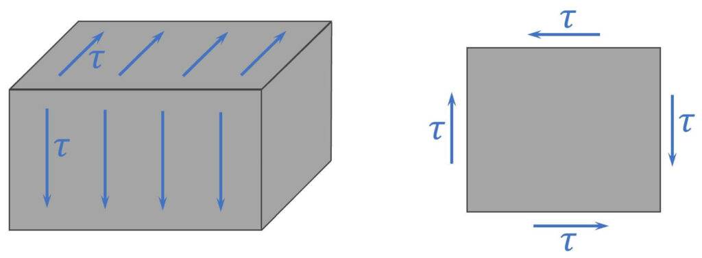
Therefore the shear force in the center of our double cross – section is equal to the horizontal shear force. The connection has to resist these horizontal shear stresses.
| Max. shear stress | $\tau_v = 0.34 MPa$ |
| Max. shear force per meter | $V_d = \tau_v \cdot w = 55.9 kN/m$ |
We verify the connection (screws) according to EN 1995-1-1 8.2.2 timber-to-timber connections with one shear plane.
| Characteristic embedment strength (ETA-11/0030) | $f_{h.k} = 0.082 \cdot \frac{\rho_k}{kg/m^3} \cdot \frac{1-0.01 \cdot d/mm}{2.5 \cdot cos(\alpha)^2 + sin(\alpha)^2} N/mm^2 = 32.4 N/mm^2$ |
| Penetration depth 1 | $t_1= min(h, l_{screw} – h) = 134mm$ |
| Penetration depth 2 | $t_2 = h = 166mm$ |
| For $\alpha <45°$ (ETA-11/0030) | $k_{ax} = 1.0$ |
| $\beta = 1$ | |
| Point side penetration length | $l_{ef} = t_1 – d = 127mm$ |
| Characteristic withdrawal capacity 1 screw (ETA-11/0030) | $F_{ax.Rk.1} = k_{ax} \cdot f_{ax.k} \cdot d \cdot l_{ef} \cdot (\frac{\rho_k}{350 kg/m^3})^{0.8} = 12.2 kN$ |
| Characteristic head pull-through capacity (ETA-11/0030) | $F_{ax.Rk.2} = f_{head.k} \cdot d_h^2 \cdot (\frac{\rho_k}{350 kg/m^3})^{0.8} = 2.1 kN$ |
| $F_{ax.Rk} = min(F_{ax.Rk.1}, F_{ax.Rk.2}) = 2.1 kN$ |
Timber-to-timber connections with one shear plane (EN 1995-1-1 (8.6)).
| EN 1995-1-1 (8.6) (a) + (b) | $F_{v.Rk.a} = f_{h.k} \cdot t_1 \cdot d = 30.4 kN$ |
| EN 1995-1-1 (8.6) (c) | $F_{v.Rk.c} = \frac{f_{h.k} \cdot t_1 \cdot d}{1+ \beta} \cdot [ \sqrt{\beta + 2 \beta^2 \cdot (1 + \frac{t_2}{t_1} + (\frac{t_2}{t_1})^2) + \beta^3 (\frac{t_2}{t_1})^2} – \beta (1+ \frac{t_2}{t_1})] + \frac{F_{ax.Rk}}{4} = 14.8 kN$ |
| EN 1995-1-1 (8.6) (d) | $F_{v.Rk.d} = 1.05 \frac{f_{h.k} \cdot t_1 \cdot d}{2+ \beta} \cdot [ \sqrt{2\beta(1 + \beta) + \frac{4 \beta (2+\beta) M_{y.Rk}}{f_{h.k} \cdot d \cdot t_1^2}} – \beta ] + \frac{F_{ax.Rk}}{4} = 11.3 kN$ |
| EN 1995-1-1 (8.6) (e) | $F_{v.Rk.e} = 1.05 \frac{f_{h.k} \cdot t_2 \cdot d}{1+ 2 \beta} \cdot [ \sqrt{2\beta^2 (1 + \beta) + \frac{4 \beta (1+2 \beta) M_{y.Rk}}{f_{h.k} \cdot d \cdot t_2^2}} – \beta ] + \frac{F_{ax.Rk}}{4} = 13.8 kN$ |
| EN 1995-1-1 (8.6) (f) | $F_{v.Rk.f} = 1.15 \cdot \sqrt{\frac{2 \beta}{1 + \beta}} \sqrt{2 M_{y.Rk} \cdot f_{h.k} \cdot d} + \frac{F_{ax.Rk}}{4} = 3.45 kN$ |
Characteristic shear strength of 1 fastener:
$$F_{v.Rk} = min(F_{v.Rk.a}, F_{v.Rk.c}, F_{v.Rk.d}, F_{v.Rk.e}, F_{v.Rk.f}) = 3.45 kN$$
Design shear resistance 1 fastener:
$$F_{v.Rd} = k_{mod} \cdot \frac{F_{v.Rk}}{\gamma_m} = 2.12 kN$$
Spacing of screws:
$$a = 70 mm$$
Number of screws per width of beam:
$$n = 2$$
Design resistance per meter:
$$F_{v.Rd} = F_{v.Rd} \cdot \frac{n}{a} = 60.6 kN/m$$
Utilization:
$$\eta = \frac{V_d}{F_{v.Rd}} = 0.92 < 1.0$$
Verification fullfilled! The horizontal shear force verifies for 2 screws per beam width with a spacing of 70 mm.
Ok, now, this is alot of screws.
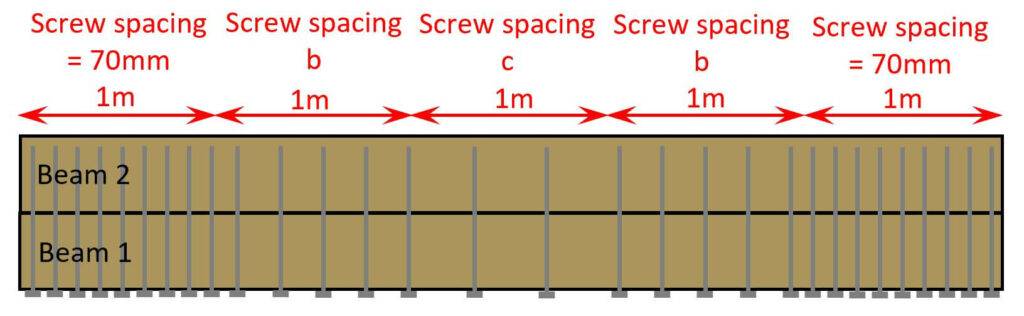
And we can optimize further. We designed the screws for the max. shear force which only acts at the supports.
If you know the shear force diagram of a simply supported beam exposed to a line load, you also know that the shear force = 0 kN at midspan. In theory, this means, that we don’t need any screws there at all.
But in reality, we never have a perfectly distributed line load on beams, so the shear force is not always 0 kN at midspan.

To optimize, we can calculate the shear forces for every meter and then calculate the required spacing of screws in that area.
| Shear force (at support) | $V_{d.max} = 12.4 kN$ |
| Shear force (1 m from support) | $V_{d.1m} = V_{d.max} – p_d \cdot 1m = 7.45 kN$ |
| Shear force (2 m from support) | $V_{d.2m} = V_{d.max} – p_d \cdot 2m = 2.5 kN$ |
Rerun the calculation from above to calculate a reduced spacing of screws from 1m – 2m and 2m – 3m.
Screw distances
We need to check one last thing – the spacing distances according to EN 1995-1-1 table 8.2. 👇👇
| Angle between force and grain | $\alpha = 90°$ | |
| Spacing parallel to grain | $a_1 = (7+8cos(\alpha)) \cdot d = 49 mm$ | 70mm |
| Spacing perpendicular to grain | $a_2 = 7 \cdot d = 49 mm$ | 70mm |
| Distance to loaded end | $a_{3.t} = 15 d = 105 mm$ | min. 105mm |
| Distance to unloaded egde | $a_{4.c} = 7d = 49 mm$ | 55mm |
SLS Deflection Verification
To calculate the instantaneous and creep deflection of the beam, we use again the full cross-section consisting of both beams.
Instantaneous deflection:
$$u_{inst} = \frac{5}{385} \cdot \frac{p_k \cdot l^4}{E_{0.mean} \cdot I_y} = 4.8mm$$
Instantaneous deflection criteria (EN 1995-1-1 Table 7.2):
$$w_{inst} = \frac{l}{300} = 16.7mm$$
Utilization:
$$\eta = \frac{u_{inst}}{w_{inst}} = 0.27 < 1.0$$
| $\psi_2$ factor for office buildings in Denmark | $\psi_2 = 0.2$ |
| Solid timber in service class 1 (EN 1995-1-1) | $k_{def} = 0.6$ |
Creep deflection – dead load:
$$u_{creep.g} = k_{def} \cdot \frac{5}{385} \cdot \frac{g_k \cdot l^4}{E_{0.mean} \cdot I_y} = 1.5mm$$
Creep deflection – live load:
$$u_{creep.q} = k_{def} \cdot \psi_2 \cdot \frac{5}{385} \cdot \frac{q_k \cdot l^4}{E_{0.mean} \cdot I_y} =0.2 mm$$
Total creep deflection:
$$u_{creep} = u_{creep.g} + u_{creep.q} = 1.8mm$$
Final deflection:
$$u_{fin} = u_{inst} + u_{creep.g} + u_{creep.q} = 6.6mm$$
Final deflection criteria (EN 1995-1-1 Table 7.2):
$$w_{fin} = \frac{l}{150} = 33.3mm$$
Utilization:
$$\eta = \frac{u_{fin}}{w_{fin}} = 0.2 < 1.0$$
Verification fullfilled!
What Are Double Timber Beams?
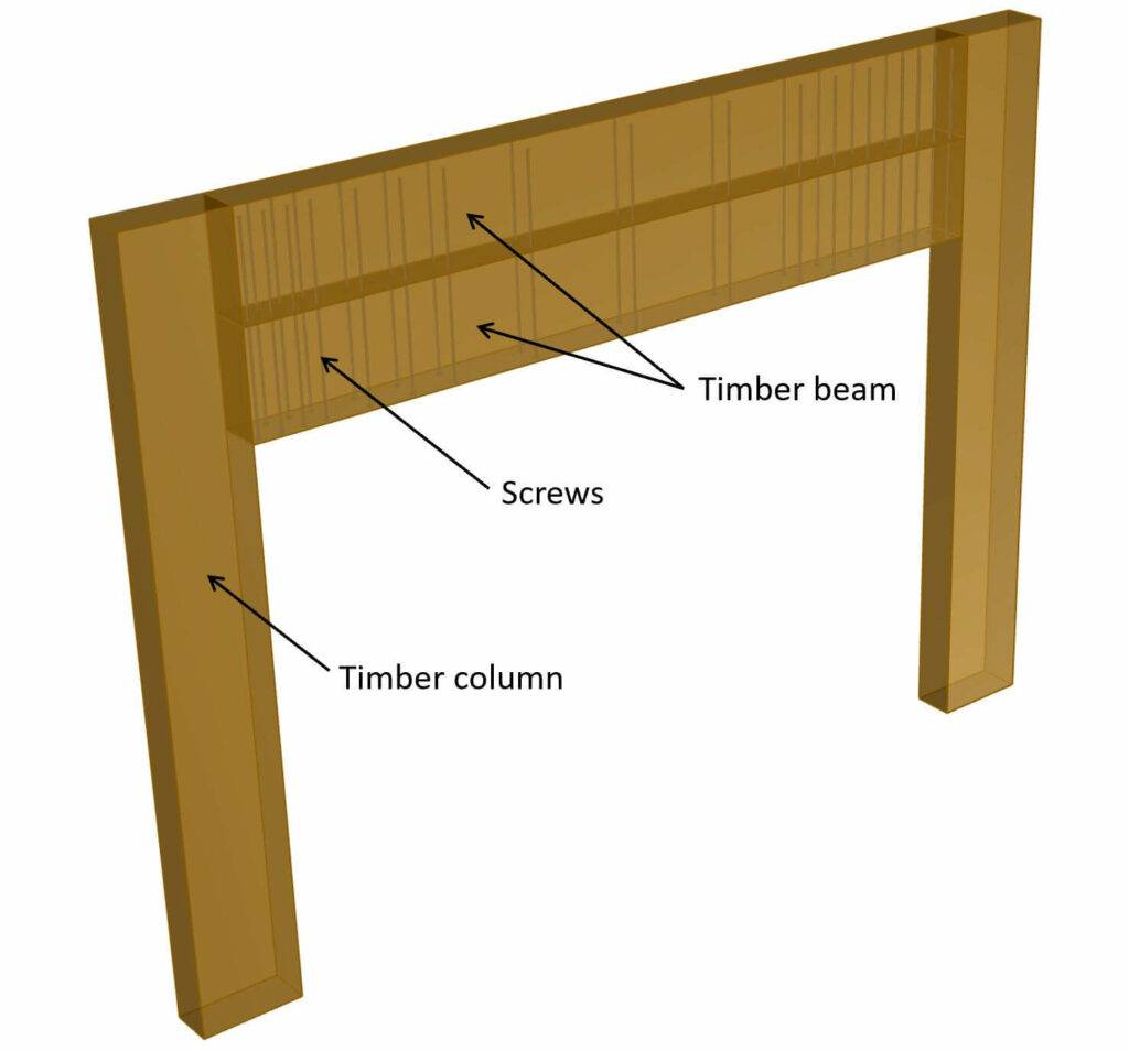
Double timber beams are two timber beams joined together to double the cross-section and increase the load bearing capacity to withstand higher loads. The two beams are joined together by screws, rods or bolts.
Conclusion
Et voila, the double timber beam is verified and dimensioned. 💯💯
If you are new to structural design, then check out more of our design tutorials where you can also learn how to design wood elements such as
But now, I would like to hear from you: Where do you want to use the double beam? Are you renovating your own house? Tell us a bit about the structure, as we all want to learn from each other.✍️
References
[1]: James M. Gere et al., (2009), Mechanincs of Materials
Double Timber Beam FAQ
Yes you can. If the connection is designed to resist the horizontal shear force between the two beams the full cross-section of both beams can be used.
You can connect a double timber beam with screws, bolts or rods. But these connectors need to resist the horizontal shear forces between the two beams and the distances between the connectors need to fullfill the requirements from Eurocode.