Reinforced Concrete Beam Design {Step-By-Step Guide}
Designing reinforced concrete beams is something structural engineering students learn early in university, as concrete is THE most used structural building material. 🙆♂️🙆♂️
Later on, structural engineers do concrete beam design over and over.
So in this post we’ll show you, step-by-step, how to design reinforced concrete beams with a worked example according to Eurocode EN 1992-1-1, what loads can act on a beam and how to calculate the design loads with load combinations.
Not much more talk, let’s dive into it. 🚀🚀
Process of Reinforced Concrete Beam Design
Before we dive into the nerdy calculations, it’s good to get an overview of the steps that need to be taken to design a concrete beam – in this case, a simply supported beam loaded with a point load.
- Calculate characteristic loads that act on the concrete beam
- Load combinations
- Define properties of concrete and reinforcement
- ULS bending verification
- ULS shear verification
- SLS crack verification
- SLS deflection verification
Example Structures of Concrete Beams
Concrete beams are used in
- Warehouse structures
- High-rise buildings
- Residential buildings
- Stadiums
- Airports
- Bridges
- Factories
- A concrete core of a high-rise building is also seen as a beam transferring the horizontal wind loads to the foundation
- Office buildings
to name a few.
The use of concrete is also dependent on the country. In some countries in-situ concrete beams are preferred while in others prefabricated beams are more common.
For example, I have lived in Germany, Austria and Denmark. In Germany and Austria almost only in-situ concrete beams are used, while in Denmark it almost never happens that you design an in-situ beam for a building. There, prefab concrete beams are the norm.
Static System of Concrete Beam
There is a variety of different static systems that the structural engineer can choose from, and often the beams act together with columns as frames.
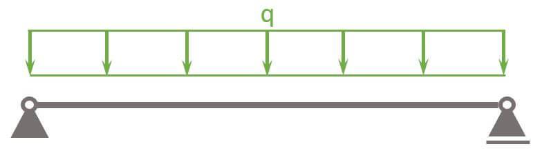
Here is the static system we are gonna use in this tutorial.
Simply Supported Beam
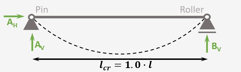
Support types
Roller & Pin
Reactions
Roller: Vertical
Pin: Vercial & Horizontal
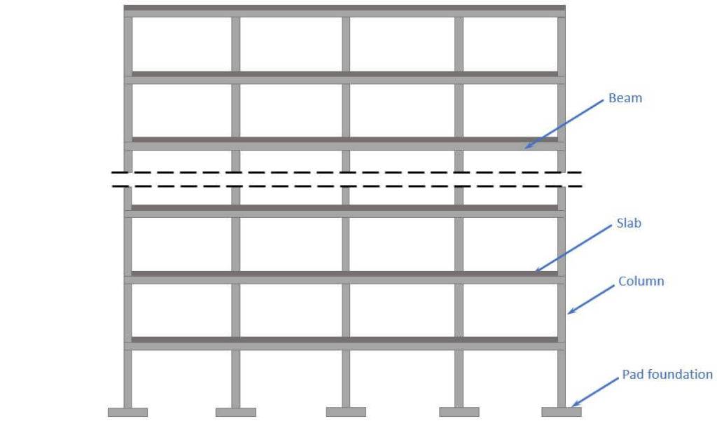
Now, let’s add some context to understand the overall statics of the building where the beam is part of.
The following picture shows where the RC beam could be used.
Characteristic Loads of RC Beam
The loads of a structure depend on its location, geometry, building type and other factors.
We’ll assume in this tutorial that we design the beam of a multi-storey office building. 🏢🏢
In this simplified design guide, the following vertical loads are considered:
Now, in the structural design of such a building other loads are also considered such as seismic, snow and wind load and imperfections.
We’ll do a lot of assumptions in this tutorial, but if you want to learn more about loads on roofs, you can check out this article.
Load transfer
❗❗ The following load transfer explanation works if the building is a traditional structure with simply supported beams and columns.❗❗
- Live and dead load (self-weight of the floor) are applied as area loads [kN/m2] on the floor slabs.
The slabs are supported by concrete beams and transfer the loads to these. - By multiplying the area loads (live and dead load) with the spacing of the beams, line loads are calculated. These line load can now be applied to the beams.
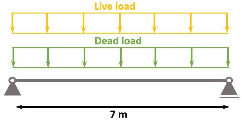
The following characteristic load values are assumptions.
| $g_{k}$ | 21 kN/m | Characteristic value of dead load |
| $q_{k}$ | 17.5 kN/m | Characteristic value of live load |
❗
The characteristic values of loads depend on a lot of different factors like location, National Annex and usage of the building to name just a few. Loads therefore need to be calculated for every structure.
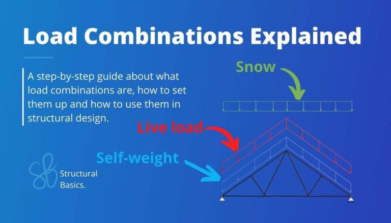
Load combinations
Load combinations combine several load cases and multiply the characteristic loads with safety factors.
Luckily, we have already written an extensive article about what load combinations are and how we use them.
In case you need to brush up on it or want to check how we derived the safety factors, you can read the blog post here.
ULS load combinations
| LC1 | $1.35 \cdot 21 kN/m $ | $28.35 kN/m$ | |
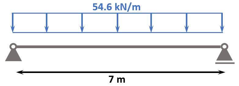
| LC2 | $1.35 \cdot 21 kN/m + 1.5 * 17.5 kN/m$ | $54.6 kN/m$ |
You can also use our load combination generator, which creates the load combinations automatically for you, and you can copy & paste the table into Word. 🔥🔥

So the design line load we are designing the reinforced concrete beam for is:
$$p_d = 54.6 kN/m$$
SLS quasi-permanent load combination
The $\psi_2.q$ factor is the reduction factor for a quasi-permanent live load of an office building. The value is according to the Danish Annex.
$$\psi_{2.q} = 0.2$$
| LC1 | $21 kN/m + \psi_{2.q} \cdot 17.5 kN/m$ | $24.5 kN/m$ |
Geometry Of The Beam
Here are the geometrical properties of the RC beam we are going to use. 👇👇
| Width | $w=0.3 m$ |
| Height | $h=0.55 m$ |
| Span | $l = 7 m$ |
Concrete And Reinforcement Properties
We’ll use the material properties from eurocodeapplied.com.
Here are the material properties we are going to use.
| Concrete compression strength | $f_{c.k}=25 MPa$ |
| Concrete tensile strength | $f_{ctm}=2.6 MPa$ |
| Partial factor in-situ concrete (Denmark) | $\gamma_c = 1.45$ |
| Design concrete compression strength | $f_{c.d}=\frac{f_{c.k}}{\gamma_c} = 17.2 MPa$ |
| Design concrete tensile strength | $f_{t.d}=\frac{f_{ctm}}{\gamma_c} = 1.8 MPa$ |
| Concrete cover | $c = 30 mm$ |
| Reinforcement yield strength | $f_{y.k} = 550 MPa$ |
| Partial factor for reinforcement (Denmark) | $\gamma_s = 1.2$ |
| Design yield strength | $f_{y.d}=\frac{f_{y.k}}{\gamma_s} = 458.3 MPa$ |
| For concrete C12-C50 | $\epsilon_{cu3} = 0.35 %$ |
| For concrete C12-C50 | $\epsilon_{c3} = 0.175 %$ |
| For concrete C12-C50 | $\lambda = 0.8 $ |
| For concrete C12-C50 | $\eta = 1.0$ |
| Reinforcement 550 MPa | $\epsilon_{y.d} = 0.208 %$ |
| E-modulus concrete | $E_{cm} = 31476 MPa$ |
| E-modulus reinforcement | $E_{s} = 200000 MPa$ |
Now, we are all set to design the in-situ concrete beam🔥🔥.
Internal Forces
We need to calculate the max. bending moment and shear force for our governing ULS load and the bending moment due to our quasi-permanent load, before we can design the reinforced concrete beam.
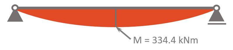
ULS Max bending moment
$$M_d = 54.6 kN/m \cdot \frac{l^2}{8} = 334.4 kNm$$
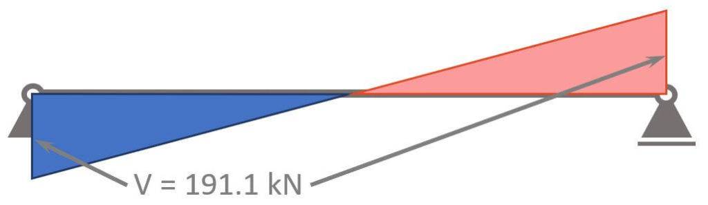
ULS Max shear force
$$V_d = 1/2 \cdot 54.6 kN/m \cdot l = 191.1 kN$$
Quasi-permanent moment
$$M_{qp} = 24.5 kN/m \cdot \frac{l^2}{8} = 150 kNm$$
ULS Bending Moment Verification
In the ULS (ultimate limit state) bending verification we design the longitudinal reinforcement of the beams.
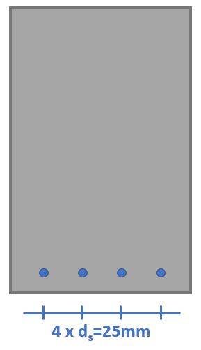
We set the diameter of the rebars to $d_s = 25 mm$.
The lever arm of the longitudinal reinforcement is calculated as
$$d = h – c – \frac{d_s}{2} = 0.508 m$$
The required reinforcement is calculated with the following formulas. 👇👇
$$\mu = \frac{M_{Ed}}{w \cdot d^2 \cdot \eta \cdot f_{c.d}} = 0.251$$
$$\omega = 1 – \sqrt{1 – 2 \cdot \mu} = 0.294$$
$$A_{s.req} = \omega \cdot \frac{w \cdot d \cdot \eta \cdot f_{c.d}}{f_{y.d}} = 1686 mm^2$$
The degree of reinforcement needs to fullfill the following equations.
$$\omega_{min} = max(0.26 \cdot \frac{f_{ctm}}{f_{y.k}} \cdot \frac{f_{y.d}}{f_{c.d}}; 0.0013 \cdot \frac{f_{y.d}}{f_{c.d}}) = 0.035$$
Verification
$$\omega > \omega_{min} = 1$$
Verification fullfilled!
$$\omega_{bal} = \lambda \cdot \frac{\epsilon_{cu3}}{\epsilon_{cu3} \cdot \epsilon_{y.d}}= 0.502$$
Verification
$$\omega < \omega_{bal} = 1$$
Verification fullfilled!
$$\omega_{max} = 0.044 \cdot \frac{f_{y.d}}{\eta \cdot f_{c.d}}= 1.17$$
Verification
$$\omega < \omega_{max} = 1$$
Verification fullfilled!
Finally, we check if the required reinforcement As.req is greater than the minimum reinforcement.
The minimum reinforcement is calculated with EN 1992-1-1 9.2.1.1 (9.1N)
$$A_{s.min} = max(0.26 \cdot \frac{f_{ctm}}{f_{y.k}} \cdot w \cdot d; 0.0013 \cdot w \cdot d) = 198.1 mm^2$$
$$A_{s.min} < A_{s.req}$$
Cross-sectional area of 1 rebar:
$$A_{s.1} = \pi \cdot (\frac{d_s}{2})^2 = 452.4 mm^2$$
Amount of rebars
$$n = roundup(\frac{A_s}{A_{s.1}}) = 4$$
Reinforcement area
$$A_s = n \cdot A_{s.1} = 1963 mm^2$$
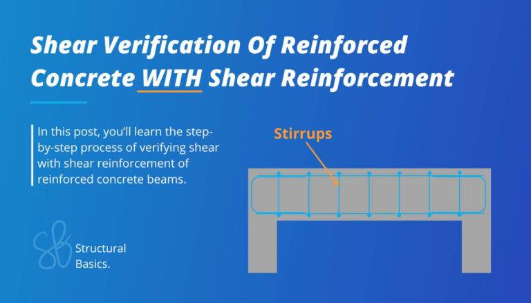
ULS Shear Verification
In case you prefer video, here’s a YouTube video explaining how to verify and design shear for reinforced concrete beams.
First we check if shear reinforcement is required according to EN 1992-1-1 6.2.2.
Members not requiring design shear reinforcement
EN 1992-1-1 6.2.2 (1)
$$k = 1 + \sqrt{\frac{200}{\frac{d}{mm}}} = 1.63$$
$$\rho_1 = min(\frac{A_s}{w \cdot d}; 0.02) = 0.013$$
Design value of the shear resistance (EN 1992-1-1 (6.2.a))
$$\upsilon_{Rd.c} = max(\frac{0.18}{\gamma_c} \cdot k \cdot (100 \rho_1 \cdot f_{c.k})^{\frac{1}{3}}; \frac{0.051}{\gamma_c} \cdot k^{\frac{3}{2}} \cdot \sqrt{f_{c.k}}) = 0.64 MPa$$
$$V_{Rd.c} = \upsilon_{Rd.c} \cdot w \cdot h = 106.1 kN$$
Shear reinforcement required because $V_d > V_{Rd.c}$.
Members requiring design shear reinforcement
EN 1992-1-1 Figure 6.5
$$z = 0.9 \cdot d = 0.457m$$
Coefficient taking into account the state of the stress in the compression chord:
$$\alpha_{cw} = 1.0$$
Strength reduction factor for concrete cracked in shear (EN 1992-1-1 (6.9))
$$\upsilon_1 = 0.6$$
$$cot(\theta) = 2.5$$
$$tan(\theta) = 0.4$$
Shear resistance (EN 1992-1-1 (6.9))
$$V_{Rd.max} = \alpha_{cw} \cdot w \cdot z \cdot \upsilon_1 \cdot \frac{f_{c.d}}{cot(\theta) + tan(\theta)} = 488.8 kN$$
Verification is fulfilled. 👇👇
$$V_d < V_{Rd.max} = 1$$
Reduction of the design yield strength of the reinforcement (EN 1992-1-1 (6.8))
$$f_{ywd} = 0.8 \cdot f_{y.k} = 440 MPa$$
Shear links (EN 1992-1-1 (6.8))
$$A_{sw} = \frac{V_d}{z \cdot f_{ywd} \cdot cot(\theta)} = 380.4 \frac{mm^2}{m}$$
Inclination of the shear reinforcement
$$\alpha = 90 deg$$
Maximum spacing (EN 1992-1-1 (9.6N))
$$s_{l.max} = 0.75 \cdot d \cdot (1 + cot(\alpha)) = 0.38 m $$
We set the spacing of the bars to s = 300 mm.
Shear reinforcement area for 1 stirrup:
$$A_{sw} = A_{sw} \cdot s = 114 mm^2$$
Required cross-sectional area for stirrup:
$$A_{sw.req} = \frac{A_{sw}}{2} = 57 mm^2$$
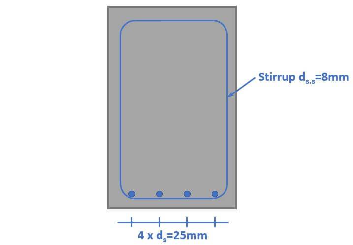
Required bar diameter:
$$d_{s.req} = \frac{2 \cdot \sqrt{A_{sw.req}}}{\pi} = 4.8 mm$$
Therefore, a stirrup diameter of $d_{s.s} = 8 mm$ is picked.
SLS Crack Width Verification
The crack width limit is found in EN 1992-1-1 Table 7.1N.
For a reinforced member in exposure class XC1, the crack width limit for a quasi-permanent load is set to 👇👇
$$w_{max} = 0.4mm$$
Now to calculate the crack width due to the quasi-permanent load 24.5 kN/m, we’ll follow the following steps.
- Calculation of the neutral axis depth of the cracked section
- Calculation of the quasi-permanent moment (we already did that)
- Calculation of the stress in the reinforcement
- Calculation of the strain
- Calculation of the max. crack spacing
- Calculation of the crack width
Alright, so let’s do that.
1. Calculation of the neutral axis depth of the cracked section
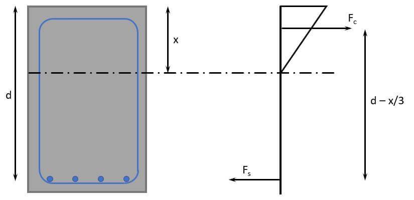
We’ll find the depth of the neutral axis by equilibrium of the first moment of areas of the tension (steel) and compression (triangle). But don’t get confused by the triangle here. When calculating the static moment of the compression zone, we only need the area of it and the lever arm is x/2.
But first, we need to calculate some parametes.
The final creep coefficient is found from [1] Table 6.12 for a notional size of $\frac{2 \cdot w \cdot h}{2 \cdot w + 2 \cdot h} = 194 mm$ as
$$\phi = 2.8$$
E-modulus of concrete long-term (quasi-permanent)
$$E_{c.eff} = \frac{E_{cm}}{1 + \phi} = 8283 MPa$$
Long-term steel – concrete ratio
$$\alpha_s = \frac{E_s}{E_{c.eff}} = 24.1$$
Update the lever arm of the longitudinal rebars with the diameter of the stirrups.
$$d = d – d_{s.s} = 500mm $$
Now, we can define the equilibrium of the 1. moment of areas. 👇👇
$$w \cdot x \cdot \frac{x}{2} = \alpha_s \cdot A_s \cdot (d-x)$$
Solving that for x leads to
$$x = \frac{\alpha_s \cdot A_s}{w} \cdot (-1 + \sqrt{1 + \frac{2 \cdot w \cdot d}{\alpha_s \cdot A_s}} = 269.6mm$$
2. Calculation of the quasi-permanent moment
We already calculated the quasi-permanent moment earlier in this article as
$$M_{qp} = 150 kNm$$
3. Calculation of the stress in the reinforcement
We calculate the stress in the reinforcement by taking moments at the location of the compressive force.
$$\sigma_s = \frac{M_{qp}}{(d-x/3) \cdot A_s} = 186.6 N/mm^2$$
4. Calculation of the strain
Factor dependent on the duration of the load EN 1992-1-1 (7.10) (long-term loading)
$$k_t = 0.4$$
$$f_{ct.eff} = f_{ctm} = 2.6 MPa$$
Effective height EN 1992-1-1 7.3.2. (3)
$$h_{c.eff} = min(2.5 \cdot (h – d); \frac{h-x}{3}; h/2) = 93.5 mm$$
$$\rho_{p.eff} = \frac{A_s}{h_{c.eff} \cdot w} = 0.07$$
EN 1992-1-1 (7.9)
$$\epsilon_{sm} – \epsilon_{cm} = max(\frac{\sigma_s – k_t \cdot \frac{f_{ct.eff}}{\rho_{p.eff}} \cdot (1 + \alpha_s \cdot \rho_{p.eff})}{E_s}; 0.6 \cdot \frac{\sigma_s}{E_s}) = 7.33 \cdot 10^{-4}$$
5. Calculation of the max. crack spacing
Coefficient EN 1992-1-1 (7.11) for high bond bars
$$k_1 = 0.8$$
Coefficient EN 1992-1-1 (7.11) for bending
$$k_2 = 0.5$$
$$s_{r.max} = 3.4 \cdot c + 0.425 \cdot k_1 \cdot k_2 \cdot \frac{d_s}{\rho_{p.eff}} = 0.163m$$
Verification
$$s_{r.max} < 5 \cdot (c + \frac{d_s}{2}) = 1$$
Verification fullfilled!
6. Calculation of the crack width
$$w_k = s_{r.max} \cdot \epsilon = 0.119 mm$$
Utilization
$$\eta = \frac{w_k}{w_{max}} = 0.30$$
SLS Deflection Verification
The deflection calculation of reinforced concrete elements is not as straightforward as for timber or steel structures. However, according to Eurocode EN 1992-1-1 the deflection requirement is likely to be satisfied if the span – effective depth ratio is less than the values given in EN 1992-1-1 Table 7.4N.
That’s what we are doing. For a simply supported beam where the concrete is highly stressed the limit is 14.
Verification
$$\frac{l}{h} = 12.7 < 14$$
Verification fullfilled!
Conclusion
Et voila, the concrete beam is verified and dimensioned. 💯💯
If you are new to structural design, then check out more of our design tutorials where you can also learn how to design wood elements such as
But now, I would like to hear from you: Have you already designed a concrete beam in university or at your work? And which semester was that in? Tell us a bit about the structure, as we all want to learn from each other.✍️
References
[1]: Bill Mosley et al., (2012), Reinforced Concrete Design to Eurocode 2
Reinforced Concrete Beam Design FAQ
– Determining loads and load combinations
– Defining beam dimensions
– Calculating the required reinforcement
– Verifying the crack width
– Considering deflection limits
This depends on the location of the beams and for what type of building the beam is used. Loads that could be considered are
– Dead load
– Live load
– Snow load
– Wind load
For the bending and shear verification the ULS load combinations according to Eurocode EN 1990 are considered.
For the SLS verification of the crack width the quasi-permanent load combination is considered.
![How To Dimension Rafters Of Purlin Roofs? [Structural Guide]](https://www.structuralbasics.com/wp-content/uploads/2022/03/How-to-design-rafters-of-purlin-roofs-768x439.jpg)