Timber Beam Design [Step-By-Step]
Wooden beams are used a lot in structural engineering, such as ceilings, roofs, garages, etc. In this blog post you will learn how to calculate the statics of a wooden beam.
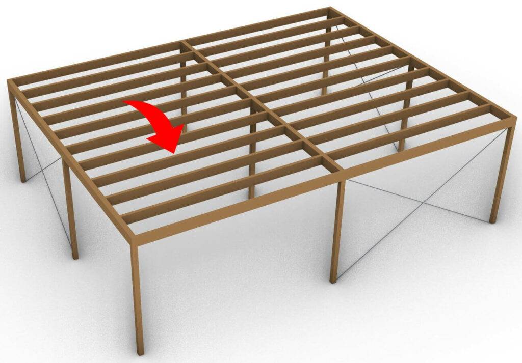
We will use the wooden beam of a flat roof as an example. 👇👇
Let’s get started. 🚀🚀
Process Of Calculating A Timber Beam
- Choose a static system, like for example a simply supported beam
- Calculate all characteristic loads (dead, snow, wind, live load, etc.)
- Calculate all load combinations
- Choose a timber material and find material properties ($k_{mod}$, $f_{c.0.k}$, $f_{m.k}$, $\gamma_{M}$)
- Assume the width w and height h of the cross-section
- Verify the beam for bending.
- Verify the beam for shear.
- Verify the beam for the instantaneous deflection criteria.
- Verify the beam for the final deflection criteria.
Static system
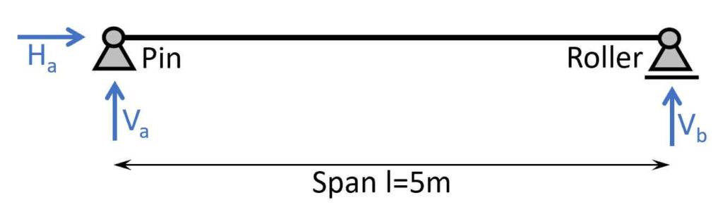
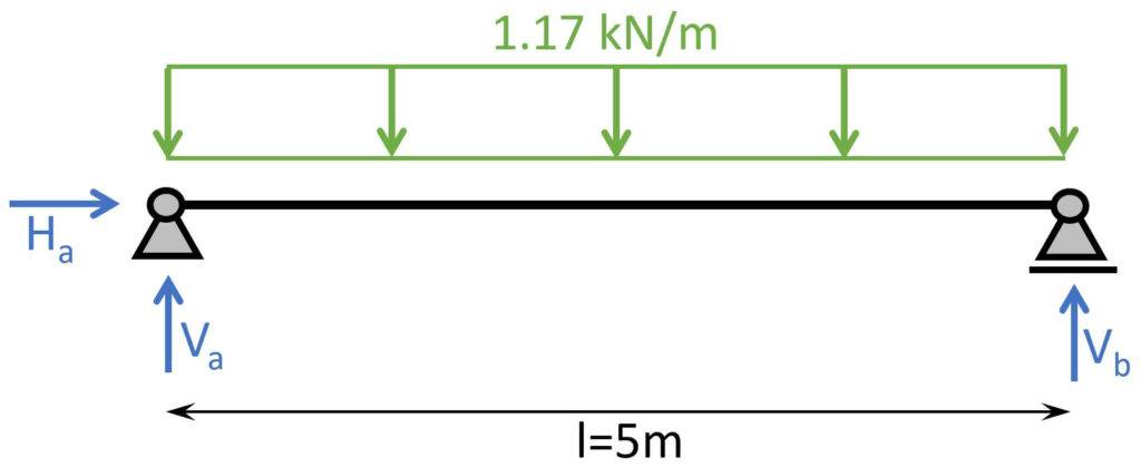
The static system of a simply supported beam can be visualized as in the next picture. It consists of one roller (takes up a vertical force V2) and one pinned support (takes up a vertical V1 and a horizontal force H1).
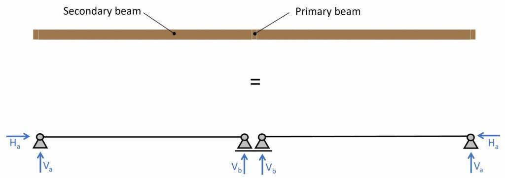
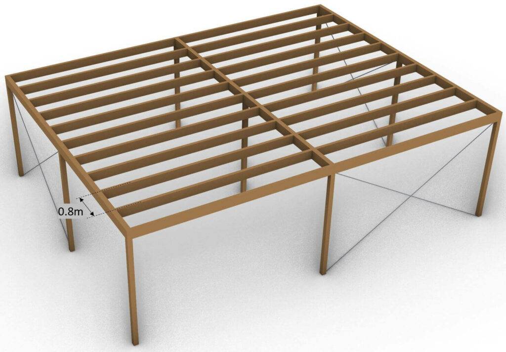
To keep it in context this simply supported beam can be a secondary beam in a flat roof.

Now when we visualize the secondary beams (dashed in picture) in a 2D section we can easily compare it to the statical system.
You can learn more about different timber roof types and how their statical systems work in this post.
Loads
We will use the loads that we assumed in our blog post about Load combinations. If you wanna learn more about the different types of loads, what they are and how to apply them, you can read that in this post.
❗
Please be aware that the loads we assumed are not tied to any region or country and that we did not extensively calculate according to Eurocode because it would have been too much information in one blog post. We will cover it in one of the next posts.
| $g_{k}$ | 1.08 kN/m2 | Characteristic value of dead load |
| $q_{k}$ | 1.0 kN/m2 | Characteristic value of live load |
| $s_{k}$ | 1.0 kN/m2 | Characteristic value of snow load |
| $w_{k}$ | -1.0 kN/m2 | Characteristic value of wind load |
Load combinations
As the basis of our calculation we will use the load combinations and loads from this blog post where we extensively explained what they are and how they work.
ULS Load combinations
| LC1 | $1.35 \cdot 1.08 \frac{kN}{m^2} $ | $1.46 \frac{kN}{m^2}$ |
| LC2 | $1.35 \cdot 1.08 \frac{kN}{m^2} + 1.5 \cdot 1.0 \frac{kN}{m^2}$ | $2.96 \frac{kN}{m^2} $ |
| LC3 | $1.35 \cdot 1.08 \frac{kN}{m^2} + 1.5 \cdot 1.0 \frac{kN}{m^2} + 0.7 \cdot 1.5 \cdot 1.0 \frac{kN}{m^2}$ | $4.0 \frac{kN}{m^2}$ |
| LC4 | $1.35 \cdot 1.08 \frac{kN}{m^2} + 0 \cdot 1.5 \cdot 1.0 \frac{kN}{m^2} + 1.5 \cdot 1.0 \frac{kN}{m^2}$ | $2.96 \frac{kN}{m^2} $ |
| LC5 | $1.35 \cdot 1.08 \frac{kN}{m^2} + 1.5 \cdot 1.0 \frac{kN}{m^2} + 0.7 \cdot 1.5 \cdot 1.0 \frac{kN}{m^2} + 0.6 \cdot 1.5 \cdot (-1.0 \frac{kN}{m^2}) $ | $3.1 \frac{kN}{m^2}$ |
| LC6 | $1.35 \cdot 1.08 \frac{kN}{m^2} + \Psi_{0} \cdot 1.5 \cdot 1.0 \frac{kN}{m^2} + 1.5 \cdot 1.0 \frac{kN}{m^2} + 0.6 \cdot 1.5 \cdot (-1.0 \frac{kN}{m^2}) $ | $2.1 \frac{kN}{m^2} $ |
| LC7 | $1.35 \cdot 1.08 \frac{kN}{m^2} + 0 \cdot 1.5 \cdot 1.0 \frac{kN}{m^2} + 0.7 \cdot 1.5 \cdot 1.0 \frac{kN}{m^2} + 1.5 \cdot (-1.0 \frac{kN}{m^2}) $ | $1.0 \frac{kN}{m^2}$ |
| LC8 | $1.35 \cdot 1.08 \frac{kN}{m^2} + 1.5 \cdot 1.0 \frac{kN}{m^2} $ | $ 2.96 \frac{kN}{m^2} $ |
| LC9 | $1.35 \cdot 1.08 \frac{kN}{m^2} + 1.5 \cdot (-1.0 \frac{kN}{m^2}) $ | $ -0.04 \frac{kN}{m^2} $ |
| LC10 | $1.35 \cdot 1.08 \frac{kN}{m^2} + 1.5 \cdot 1.0 \frac{kN}{m^2} + 0.6 \cdot 1.5 \cdot (-1.0 \frac{kN}{m^2}) $ | $ 2.06 \frac{kN}{m^2}$ |
| LC11 | $1.35 \cdot 1.08 \frac{kN}{m^2} + 1.5 \cdot (-1.0 \frac{kN}{m^2}) + 0.7 \cdot 1.5 \cdot 1.0 \frac{kN}{m^2} $ | $1.0 \frac{kN}{m^2}$ |
| LC12 | $1.35 \cdot 1.08 \frac{kN}{m^2} + 1.5 * 1.0 \frac{kN}{m^2} + 0.6 \cdot 1.5 \cdot (-1.0 \frac{kN}{m^2})$ | $2.06 \frac{kN}{m^2}$ |
Characteristic SLS Load combinations
| LC1 | $1.08 \frac{kN}{m^2} $ | $1.08 \frac{kN}{m^2}$ |
| LC2 | $1.08 \frac{kN}{m^2} + 1.0 \frac{kN}{m^2}$ | $2.08 \frac{kN}{m^2}$ |
| LC3 | $1.08 \frac{kN}{m^2} + 1.0 \frac{kN}{m^2} + 0.7 \cdot 1.0 \frac{kN}{m^2}$ | $2.78 \frac{kN}{m^2}$ |
| LC4 | $1.08 \frac{kN}{m^2} + 1.0 \frac{kN}{m^2} + 0.6 \cdot (-1.0 \frac{kN}{m^2})$ | $1.48 \frac{kN}{m^2}$ |
| LC5 | $1.08 \frac{kN}{m^2} + 1.0 \frac{kN}{m^2} + 0.7 \cdot 1.0 \frac{kN}{m^2} + 0.6 \cdot (-1.0 \frac{kN}{m^2}) $ | $2.18 \frac{kN}{m^2}$ |
| LC6 | $1.08 \frac{kN}{m^2} + 0 \cdot 1.0 \frac{kN}{m^2} + 1.0 \frac{kN}{m^2} + 0.6 \cdot (-1.0 \frac{kN}{m^2}) $ | $1.48 \frac{kN}{m^2}$ |
| LC7 | $1.08 \frac{kN}{m^2} + 0 \cdot 1.0 \frac{kN}{m^2} + 0.7 \cdot 1.0 \frac{kN}{m^2} + (-1.0 \frac{kN}{m^2}) $ | $0.78 \frac{kN}{m^2}$ |
| LC8 | $1.08 \frac{kN}{m^2} + 1.0 \frac{kN}{m^2}$ | $2.08 \frac{kN}{m^2}$ |
| LC9 | $1.08 \frac{kN}{m^2} + (-1.0 \frac{kN}{m^2}) $ | $0.08 \frac{kN}{m^2}$ |
| LC10 | $1.08 \frac{kN}{m^2} + 1.0 \frac{kN}{m^2} + 0.6 \cdot (-1.0 \frac{kN}{m^2}) $ | $1.48 \frac{kN}{m^2}$ |
| LC11 | $1.08 \frac{kN}{m^2} + (-1.0 \frac{kN}{m^2}) + 0.7 \cdot 1.0 \frac{kN}{m^2} $ | $0.78 \frac{kN}{m^2}$ |
| LC12 | $1.08 \frac{kN}{m^2} + 0 \cdot 1.0 \frac{kN}{m^2} + 1.0 \frac{kN}{m^2}$ | $2.08 \frac{kN}{m^2}$ |
| LC13 | $1.08 \frac{kN}{m^2} + 0 \cdot 1.0 \frac{kN}{m^2} + (-1.0 \frac{kN}{m^2})$ | $0.08 \frac{kN}{m^2}$ |
Beam timber material
First, the designer needs to pick between structural wood and engineered wood, such as Glulam (Glued-laminated timber) or LVL (Laminated Veneer Lumber).
Which the designer picks depend on the project, spans, cost and the personal taste.
So for our beam example we are using a structural timber C24.
Now we need to find the properties of this timber, and we can either find it in Eurocode or we find a manufacturer online which has tables of its timber products.
We found a C24 beam from a manufacturer online with the following properties.
| Bending strength $f_{m.k}$ | 24 $\frac{N}{mm^2}$ |
| Tension strength parallel to grain $f_{t.0.k}$ | 14 $\frac{N}{mm^2}$ |
| Tension strength perpendicular to grain $f_{t.90.k}$ | 0.4 $\frac{N}{mm^2}$ |
| Compression strength parallel to grain $f_{c.0.k}$ | 21 $\frac{N}{mm^2}$ |
| Compression strength perpendicular to grain $f_{c.90.k}$ | 2.5 $\frac{N}{mm^2}$ |
| Shear strength $f_{v.k}$ | 4.0 $\frac{N}{mm^2}$ |
| E-modulus $E_{0.mean}$ | 11.0 $\frac{kN}{mm^2}$ |
Modification factor kmod
The modification factor $k_{mod}$ takes into account the effects of the moisture content and the load duration on the properties of the timber.
This factor will be used to calculate the design stresses in timber elements.
The moisture content is split up in 3 categories or so-called Service classes.
Those service classes express how exposed a timber element is to moisture, meaning that an element that is exposed to rain can be put in service class 3 whereas an element inside of a building can be put in service class 1.
The detailed description can be found in EN 1995-1-1 2.3.1.3.
The load duration classes express how long a load acts on a structure because the longer, the greater the reduction of the timber properties will be.
The dead load, as an example, acts on a structure permanently while a wind load acts only for a short time and therefore can be classified as an instantaneous load.
The load duration classes can be found in EN 1995-1-1 Table 2.2.
Now in our case we are assuming that we are designing a flat roof of a residential house. The beams are not exposed to weather. Therefore we have Service class 1.
Furthermore, we can also define the load duration of the loads that are acting on our flat roof according to EN 1995-1-1 Table 2.2.
| Self-weight/dead load | Permanent |
| Live load, Snow load | Medium-term |
| Wind load | Instantaneous |
❗
The snow load can also be categorized as a short-term load. This depends on the location and the National Annex.
We can now find the values of $k_{mod}$ for C24 structural wood (Solid timber) and our different loads according to EN 1995-1-1 Table 3.1
| kmod | |||
|---|---|---|---|
| Self-weight/dead load | Permanent action | Service class 1 | 0.6 |
| Live load, Snow load | Medium term action | Service class 1 | 0.8 |
| Wind load | Instantaneous action | Service class 1 | 1.1 |
Partial Factor
The partial factor $\gamma_{M}$ takes into account material properties at ULS. EN 1995-1-1 Table 2.3 represents recommended partial factors.
❗
Please be aware that those factors can vary from country to country. So please make sure to check those values with your National Annex.
In our case for solid timber, we get the partial factor of
$$\gamma_{M} = 1.3$$
Assumption of width and height of beam
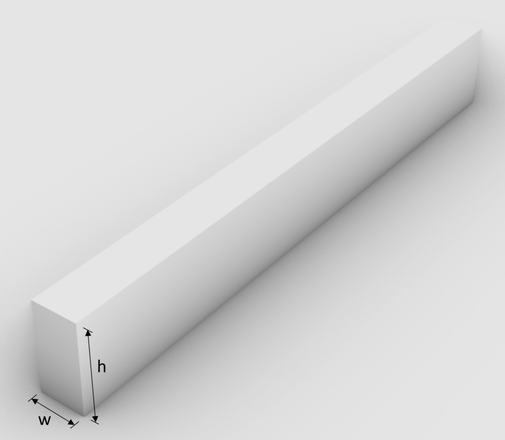
Before we now can finally start with the design of the beam, we need to define the width and height of the beam cross-section. This is based on the experience of the designer.
❗
I highly recommend doing any calculation in a program where you can always update values and not by hand on a piece of paper! I made that mistake in my bachelor. In any course and even in my bachelor thesis, I calculated everything except the forces (FE program) on a piece of paper.
Check out this article to digitize your hand calculations.
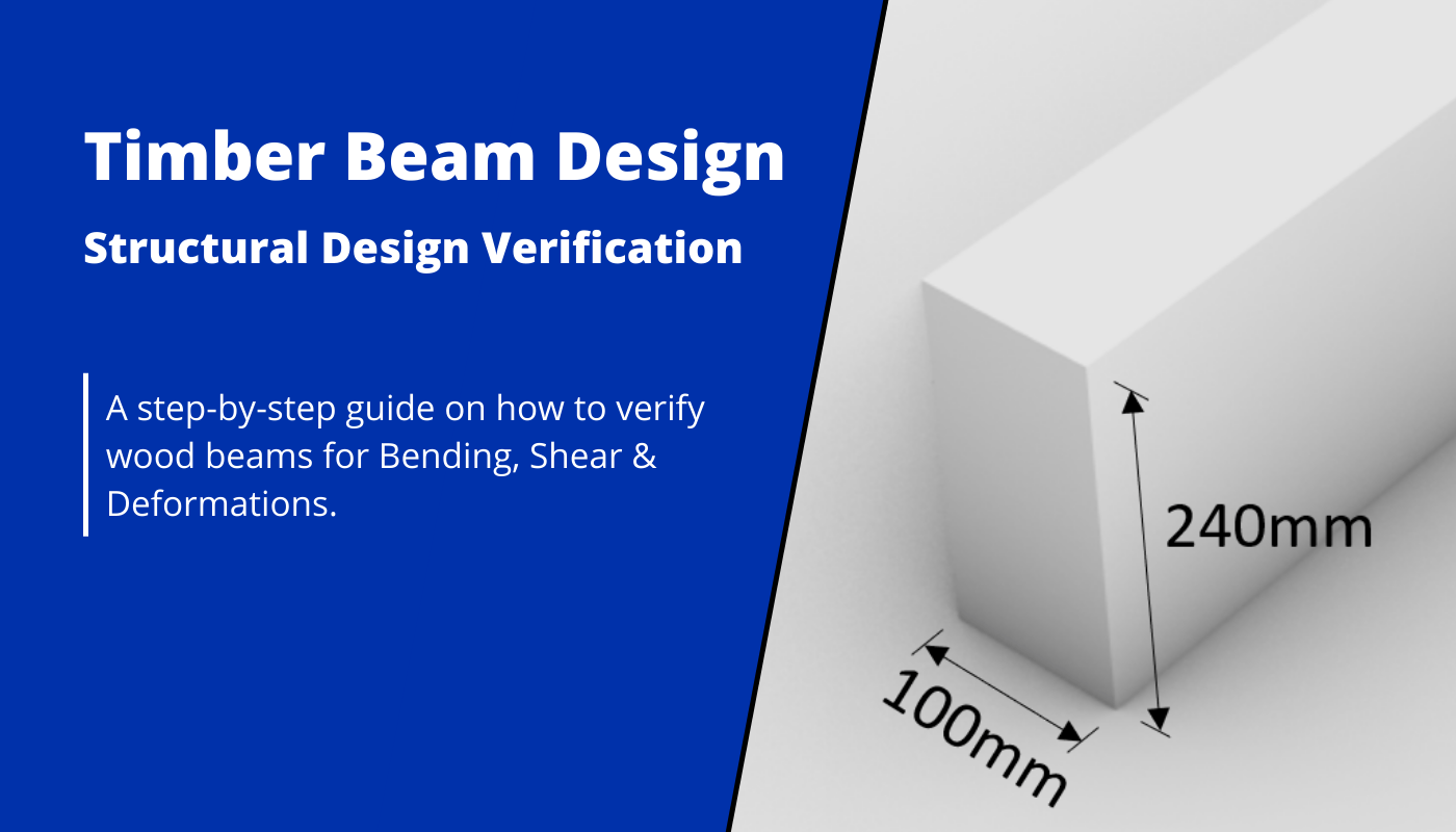
Width w = 80 mm
Height h = 240 mm
❗
Please make sure that you do not choose random values here. The values you choose should also be available in the market. Check the tables on the manufacturer homepages.
Once we know the height and width of the cross-section we can calculate the moment of inertia of the strong axis which is needed to calculate the stress due to bending.
$I_{y} = \frac{w \cdot h^3}{12} = \frac{80mm \cdot (240mm)^3}{12} = 9.22 \cdot 10^7 mm^4 $
ULS Design
In the ULS (ultimate limit state) Design we verify the stresses in the timber members due to bending and shear.
Before we start calculating anything we need to pick out the worst case loadcombinations for permanent, medium-term and instantaneous actions meaning the highest values because those actions lead to different resistance stresses due to different $k_{mod}$ values.
| LC1 (P-action) | $1.35 \cdot 1.08 \frac{kN}{m^2} $ | $1.46 \frac{kN}{m^2}$ |
| LC3 (L-action) | $1.35 \cdot 1.08 \frac{kN}{m^2} + 1.5 \cdot 1.0 \frac{kN}{m^2} + 0.7 \cdot 1.5 \cdot 1.0 \frac{kN}{m^2}$ | $4.0 \frac{kN}{m^2}$ |
| LC5 (I-action) | $1.35 \cdot 1.08 \frac{kN}{m^2} + 1.5 \cdot 1.0 \frac{kN}{m^2} + 0.7 \cdot 1.5 \cdot 1.0 \frac{kN}{m^2} + 0.6 \cdot 1.5 \cdot (-1.0 \frac{kN}{m^2}) $ | $3.1 \frac{kN}{m^2}$ |
Since we will design a beam in 2D we need to transform the area loads ($\frac{kN}{m^2}$) into line loads ($\frac{kN}{m}$). We do this by multiplication with the distance between the centerlines of 2 beams.
| LC1 (P-action) | $1.46 \frac{kN}{m^2} \cdot 0.8m $ | $1.17 \frac{kN}{m} $ |
| LC3 (L-action) | $4.0 \frac{kN}{m^2} \cdot 0.8m $ | $3.2 \frac{kN}{m} $ |
| LC5 (I-action) | $3.1 \frac{kN}{m^2} \cdot 0.8m $ | $2.48 \frac{kN}{m} $ |
Those line loads can now be applied to our statical system. As an example we apply the load of LC1.
Bending
From the 3 leading Loadcombinations LC1, LC3 and LC5 we can go ahead and calculate the most critical bending moment. The highest bending moment in a simply supported beam is found in the midspan and can be calculated with the following formula:
$M_{d} = q \cdot \frac{L^2}{8}$
Where
- $q$ is the applied load on the beam
- $L$ is the span
This results in the following bending moments due to LC1, LC3 and LC5
| LC1 (P-action) | $1.17 \frac{kN}{m} \cdot \frac{(5m)^2}{8} $ | $3.66 kNm $ |
| LC3 (L-action) | $3.2 \frac{kN}{m} \cdot \frac{(5m)^2}{8} $ | $10 kNm $ |
| LC5 (I-action) | $2.48 \frac{kN}{m} \cdot \frac{(5m)^2}{8} $ | $7.75 kNm $ |
From the bending moment, we can calculate the stress in the most critical cross-section (midspan for simply supported beam).
$\sigma = \frac{M_{d}}{I_{y}} \cdot \frac{h}{2}$
| LC1 (P-action) | $\frac{3.66 kNm}{9.22 \cdot 10^7 mm^4} \cdot \frac{0.24m}{2} $ | $4.76 MPa $ |
| LC3 (L-action) | $\frac{10 kNm}{9.22 \cdot 10^7 mm^4} \cdot \frac{0.24m}{2} $ | $13.0 MPa $ |
| LC5 (I-action) | $\frac{7.75 kNm}{9.22 \cdot 10^7 mm^4} \cdot \frac{0.24m}{2} $ | $10.1 MPa $ |
The last step, before we can check whether or not the cross section can resist the loads, is calculating the Resistance stresses of the timber material.
$ f_{m.d} = k_{mod} \cdot \frac{f_{m.k}}{\gamma_{m}} $
| LC1 (P-action) | $k_{mod.P} \cdot \frac{f_{m.k}}{\gamma_{m}} $ | $0.6 \cdot \frac{24 MPa}{1.3} $ | $11.1 MPa $ |
| LC3 (L-action) | $k_{mod.L} \cdot \frac{f_{m.k}}{\gamma_{m}} $ | $0.8 \cdot \frac{24 MPa}{1.3} $ | $14.77 MPa $ |
| LC5 (I-action) | $k_{mod.I} \cdot \frac{f_{m.k}}{\gamma_{m}} $ | $1.1 \cdot \frac{24 MPa}{1.3} $ | $20.31 MPa $ |
Finally, we can calculate the utilization of the cross-section at its most critical point.
$\eta = \frac{\sigma}{f_{m.d}}$
| LC1 (P-action) | $\frac{\sigma.P}{f_{m.d.P}} $ | $\frac{4.76 MPa}{11.1 MPa} $ | $ 0.43 $ |
| LC3 (L-action) | $\frac{\sigma.L}{f_{m.d.L}} $ | $\frac{13 MPa}{14.77 MPa} $ | $ 0.88 $ |
| LC5 (I-action) | $\frac{\sigma.I}{f_{m.d.I}} $ | $\frac{10.1 MPa}{20.31 MPa} $ | $ 0.5 $ |
💡
Our beam is verified for bending because the largest loads (LC3) lead to 88% utilization of the beam. If that value is > 100% then our beam would not be verified, we would increase the cross-section dimensions and do the calculations again until all utilizations are < 100%.
Shear
Like in bending from the 3 leading load combinations LC1, LC3 and LC5 we can go ahead and calculate the most critical shear force. The highest shear force in a simply supported beam is found near the 2 supports and can be calculated with the following formula:
$$V_{d} = q * \frac{L}{2}$$
Where
- $q$ is the applied load on the beam
- $L$ is the span
This results in the following shear forces due to LC1, LC3 and LC5
| LC1 (P-action) | $1.17 \frac{kN}{m} \cdot \frac{5m}{2} $ | $2.93 kN $ |
| LC3 (L-action) | $3.2 \frac{kN}{m} \cdot \frac{5m}{2} $ | $8 kN $ |
| LC5 (I-action) | $2.48 \frac{kN}{m} \cdot \frac{5m}{2} $ | $6.2 kN $ |
From the shear forces, we can calculate the stress in the most critical cross-section (near support for simply supported beam).
$\tau = \frac{3}{2} \cdot \frac{V_{d}}{w \cdot h} $
| LC1 (P-action) | $\frac{3}{2} \cdot \frac{2.93 kN}{0.08m \cdot 0.24m} $ | $0.23 MPa $ |
| LC3 (L-action) | $\frac{3}{2} \cdot \frac{8 kN}{0.08m \cdot 0.24m} $ | $0.63 MPa $ |
| LC5 (I-action) | $\frac{3}{2} \cdot \frac{6.2 kN}{0.08m \cdot 0.24m} $ | $0.48 MPa $ |
The last step, before we can check whether the cross-section can resist the loads, is calculating the shear resistance stresses of the timber material.
$$f_{v.d} = k_{mod} * \frac{f_{v.k}}{\gamma_{m}}$$
| LC1 (P-action) | $k_{mod.P} \cdot \frac{f_{v.k}}{\gamma_{m}} $ | $0.6 \cdot \frac{4 MPa}{1.3} $ | $1.85 MPa $ |
| LC3 (L-action) | $k_{mod.L} \cdot \frac{f_{v.k}}{\gamma_{m}} $ | $0.8 \cdot \frac{4 MPa}{1.3} $ | $2.46 MPa $ |
| LC5 (I-action) | $k_{mod.I} \cdot \frac{f_{v.k}}{\gamma_{m}} $ | $1.1 \cdot \frac{4 MPa}{1.3} $ | $3.39 MPa $ |
Finally we can calculate the utilization of the cross section at its most critical point.
$$\eta = \frac{\tau}{f_{v.d}}$$
| LC1 (P-action) | $\frac{\tau.P}{f_{v.d.P}} $ | $\frac{0.23 MPa}{1.85 MPa} $ | $ 0.124 $ |
| LC3 (L-action) | $\frac{\tau.L}{f_{v.d.L}} $ | $\frac{0.63 MPa}{2.46 MPa} $ | $ 0.25 $ |
| LC5 (I-action) | $\frac{\tau.I}{f_{v.d.I}} $ | $\frac{0.48 MPa}{3.39 MPa} $ | $ 0.14 $ |
💡
Our beam is verified for shear because the largest loads (LC3) lead to only 25% utilization of the beam. If that value is > 100% then our beam would not be verified, we would increase the cross-section dimensions and do the calculations again until all utilizations are < 100%
SLS Design
💡
In the SLS (serviceability limit state) Design of a beam we verify that the deflection does not exceed either the values from Eurocode or values agreed on with the client.
Deflection
Before we start calculating anything we need to define a few variables from EN 1995-1-1 Figure 7.1
- $w_{c}$ is the precamber
- $w_{inst}$ is the instantaneous deformation
- $w_{creep}$ is the creep deformation
- $w_{fin}$ is the final deformation: $w_{inst} + w_{creep}$
- $w_{net.fin}$ is the net final deformation: $w_{inst} + w_{creep} – w_{c}$
EN 1995-1-1 Table 7.2 recommends values for $w_{inst}, w_{net.fin}$ and $w_{fin}$ which should not be exceeded for a simply supported beam.
| $w_{inst}$ | $w_{net.fin}$ | $w_{fin}$ |
| $L/300$ to $L/500$ | $L/250$ to $L/350 $ | $L/150$ to $L/300 $ |
With a beam length (span) of L=5m we get the following values.
| $w_{inst}$ | $w_{net.fin}$ | $w_{fin}$ |
| 16.67mm to 10mm | 20mm to 14.3mm | 33.3mm to 16.67mm |
Instantaneous deformation $u_{inst}$
$u_{inst}$ (instantaneous deformation) of our beam can be calculated with the load of the characteristic loadcombination. Looking at all loadcombinations we can see that LC3 leads to the biggest load where the live load is the leading and the snow load the accompanying variable action.
| LC3 | $1.08 \frac{kN}{m^2} + 1.0 \frac{kN}{m^2} + 0.7 * 1.0 \frac{kN}{m^2}$ | $2.78 \frac{kN}{m^2}$ |
Transforming this load into a line load gives us:
$2.78 \frac{kN}{m^2} \cdot 0.8m = 2.22 \frac{kN}{m}$
Which we now can put in the deflection formula for line loads on simply supported beams.
$$u_{inst} = \frac{5}{384} \cdot q \cdot \frac{L^4}{E_{0.mean} \cdot I_{y}} $$
$$u_{inst} = \frac{5}{384} \cdot 2.22 \frac{kN}{m} \cdot \frac{(5m)^4}{11 \frac{kN}{mm^2} \cdot 9.22 \cdot 10^7 mm^4} = 17.85mm$$
Finally we can check the utilization.
$$\eta = \frac{u_{inst}}{w_{inst}}$$
$$\eta = \frac{17.85mm}{16.67mm} = 1.07$$
❌
Unfortunately, the instantaneous deflection criteria is not verified. Therefore, the Cross-section dimensions need to be increased.
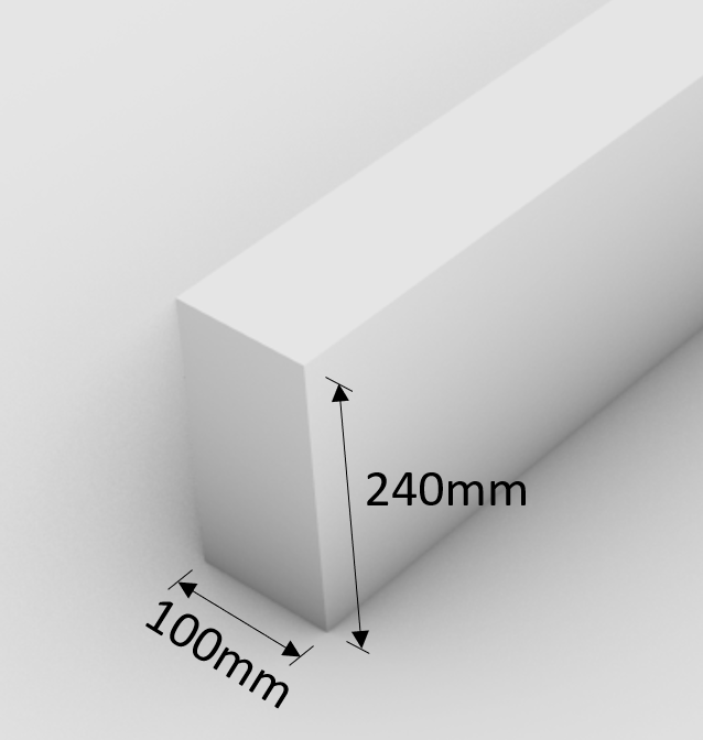
Increase of Cross-section dimensions
Width w = 100 mm
Height h = 240 mm
Moment of inertia $I_{y} = 1.15 * 10^8 mm^4 $
Now we run the deflection calculation again with the updated dimensions.
$$ \frac{5}{384} * 2.22 \frac{kN}{m} * \frac{(5m)^4}{11 \frac{kN}{mm^2} * 1.15 * 10^8 mm^4} = 14.28mm$$
and the utilization.
$$\eta = \frac{14.28mm}{16.67mm} = 0.85$$
✔️
Now the instantaneous deflection criteria is verified.
Final deformation $u_{fin}$
$u_{fin}$ (final deformation) of our beam can be calculated by adding the creep deformation $u_{creep}$ to the instantaneous deflection $u_{inst}$. Therefore we will look at how we calculate the creep deflection of LC3.
The creep deformation due to dead load is calculated as
$$u_{creep.g} = u_{inst.g} \cdot k_{def} $$
$$u_{creep.g} = \frac{5}{384} \cdot g_{k} \cdot \frac{L^4}{E_{0.mean} \cdot I_{y}} \cdot k_{def}$$
Where
$k_{def} $ is given in EN 1995-1-1 for solid timber in Service class 1 as 0.6.
$$u_{creep.g} = \frac{5}{384} \cdot 0.86 \frac{kN/m} \cdot \frac{(5m)^4}{11 \frac{kN}{mm^2} \cdot 1.15 \cdot 10^8 mm^4 } \cdot 0.6$$
$$u_{creep.g} = 3.33 mm$$
The creep deformation due to the leading variable action (live load in our case – LC3) is calculated as
$$u_{creep.q} = u_{inst.q} \cdot k_{def} \cdot \Psi_{2.q} $$
$$u_{creep.q} = \frac{5}{384} \cdot q_{k} \cdot \frac{L^4}{E_{0.mean} \cdot I_{y}} \cdot k_{def} \cdot \Psi_{2.q}$$
Where
$\Psi_{2.q} $ is given in EN 1990 Table A1.1 for imposed loads on roofs as 0.
$$u_{creep.q} = \frac{5}{384} \cdot 0.8 \frac{kN/m} \cdot \frac{(5m)^4}{11 \frac{kN}{mm^2} \cdot 1.15 \cdot 10^8 mm^4 } \cdot 0.6 \cdot 0$$
$$u_{creep.q} = 0$$
The creep deformation due to the accompanyied variable action (snow load in our case – LC3) is calculated as
$$u_{creep.s} = u_{inst.s} \cdot k_{def} \cdot \Psi_{2.s} $$
$$u_{creep.s} = \frac{5}{384} \cdot q_{k} \cdot \frac{L^4}{E_{0.mean} \cdot I_{y}} \cdot k_{def} \cdot \Psi_{2.s}$$
Where
$\Psi_{2.s} $ is given in EN 1990 Table A1.1 for snow loads in Sweden as 0.2
$$u_{creep.s} = \frac{5}{384} \cdot 0.8 \frac{kN/m} \cdot \frac{(5m)^4}{11 \frac{kN}{mm^2} \cdot 1.15 \cdot 10^8 mm^4 } \cdot 0.6 \cdot 0.2$$
$$u_{creep.s} = 0.43 mm$$
Adding the creep to the instantaneous deflection leads to the final deflection.
$$u_{fin} = u_{inst} + u_{creep.g} + u_{creep.q} + u_{creep.s}$$
$$u_{fin} = 14.28mm + 3.33mm + 0mm + 0.43mm = 18.04mm$$
This leads to a utilization of
$$\eta = \frac{18.04mm}{33.3mm} = 0.54$$
✔️
The final deflection criteria is verified, and therefore the beam is verified for the dimensions of w=100mm and h=240mm.
![11 Types of Trusses [The MOST Used]](https://www.structuralbasics.com/wp-content/uploads/2022/12/Different-types-of-trusses-768x439.jpg)