Moment Of Inertia Of A Cracked Reinforced Concrete Section
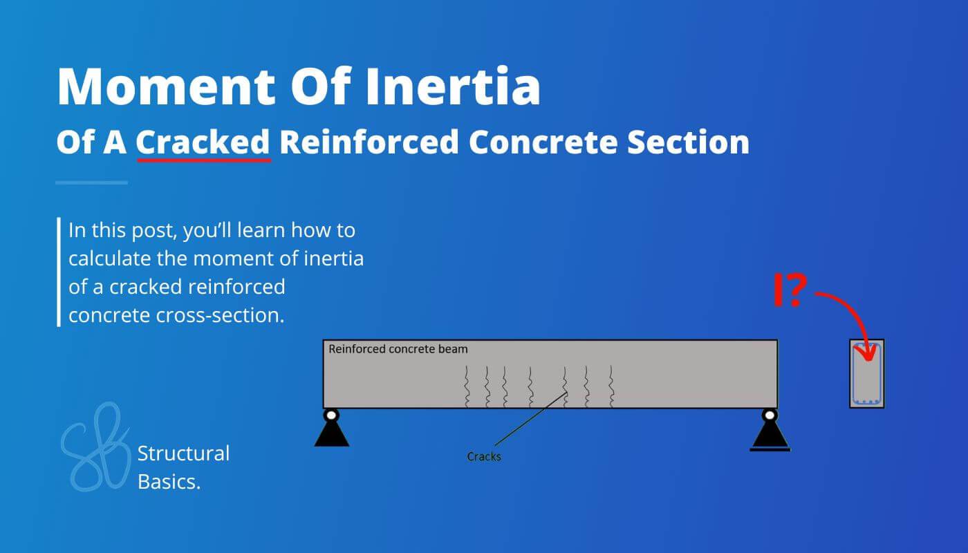
Most reinforced concrete beams have cracks, leading to a reduced stiffness. In structural verifications of reinforced concrete elements like beams, we use the moment of inertia as the representation of the stiffness.
Cracks happen, when the tensile stress resistance of concrete is reached. Then the concrete can’t take up any tensile forces any more and the reinforcement gets activated and takes up all tensile forces.
Here’s the formula of the moment of inertia of a cracked reinforced concrete section (you can find a step-by-step calculation later in the article 👇👇):
$$I_a = \frac{w \cdot x^3}{12} + w \cdot x \cdot (x/2)^2 + \alpha \cdot A_{s.t} \cdot (d_{eff.b} – x)^2$$
In some situations, reinforced concrete sections are not cracked. In that case, the moment of inertia is a lot bigger. Check out this guide to learn how to calculate it for uncracked sections.
Alright, let’s get started. 🚀🚀
Process Of Calculating The Moment Of Inertia Of A Cracked Reinforced Concrete Section
Here are the steps, we need to follow to calculate the moment of inertia of a cracked rectangular reinforced concrete section (we’ll calculate and define all parameters in the next section):
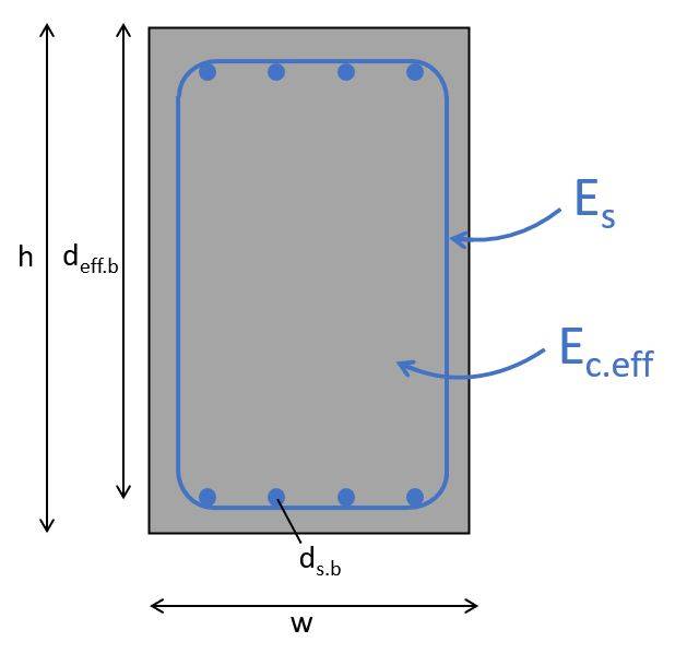
- Define the geometrical and material properties of the reinforced concrete section (Longitudinal reinforcement at bottom ds.b and top ds.t, effective height of the reinforcement deff, E-moduli of steel Es and concrete Ec.eff, cross-sectional dimensions h and b, etc.)
- Ratio between moduli:
$$\alpha = \frac{E_s}{E_{c.eff}}$$ - Height of the compression area:
$$x = \frac{\alpha \cdot A_{s.b}}{w} \cdot (-1 + \sqrt{1 + \frac{2 \cdot w \cdot d_{eff.b}}{\alpha \cdot A_{s.b}}})$$ - Moment of inertia (cracked section)
$$I_a = \frac{w \cdot x^3}{3} + \alpha \cdot A_{s.t} \cdot (d_{eff.b} – x)^2$$
In the last section of this post, we’ll run through an example calculation of a cracked reinforced concrete cross-section. 👇👇
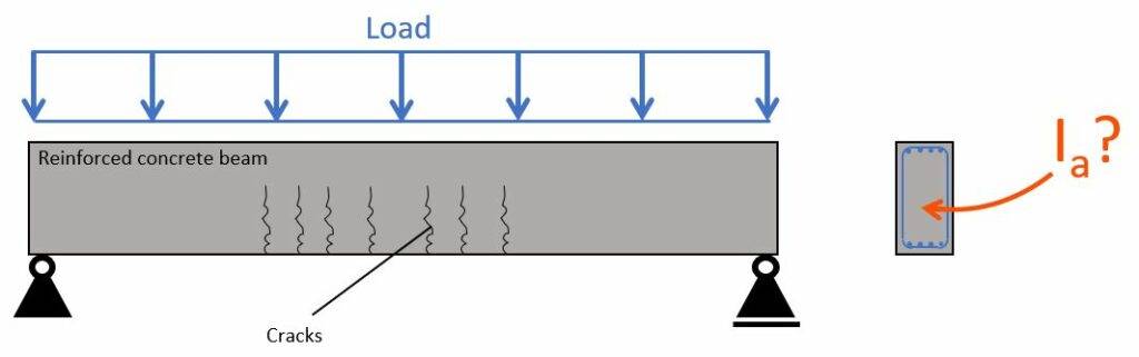
Example Calculation Of The Moment Of Inertia
Now, let’s apply this to an example with the following parameters.
Geometrical parameters
| Cross-sectional height | $h = 400 mm$ |
| Cross-sectional width | $w = 300 mm$ |
| Concrete cover | $c = 25 mm$ |
| Stirrup diameter | $d_{s.s} = 8 mm$ |
| Bottom reinforcement – diameter | $d_{s.b} = 16 mm$ |
| Bottom reinforcement – number of bars | $n_{s.b} = 4$ |
| Bottom reinforcement – effective height | $d_{eff.b} = h – c – d_{s.s} – d_{s.b}/2 = 41 mm$ |
| Bottom reinforcement – cross-sectional area | $A_{s.b} = n_{s.b} \cdot (d_{s.b}/2)^2 \cdot \pi = 804.2 mm^2$ |
Material parameters
| E-modulus of reinforcement | $E_s = 200 GPa$ |
| E-modulus of concrete (C25) EN 1992-1-1 Table 3.1 | $E_{cm} = 31 GPa$ |
| Creep factor (assumption*) | $\varphi_{28} = 2.0$ |
| Effective e-modulus of concrete | $E_{c.eff} = \frac{E_{cm}}{1 + \varphi_{28}} = 10.3 GPa$ |
1. First, we’ll calculate the ratio between the reinforcement and concrete moduli:
$$\alpha = \frac{E_s}{E_{c.eff}} = 19.4$$
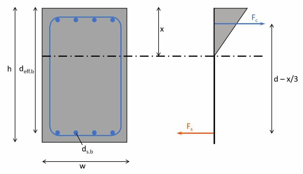
2. Next, we’ll calculate the neutral axis of the cracked section:
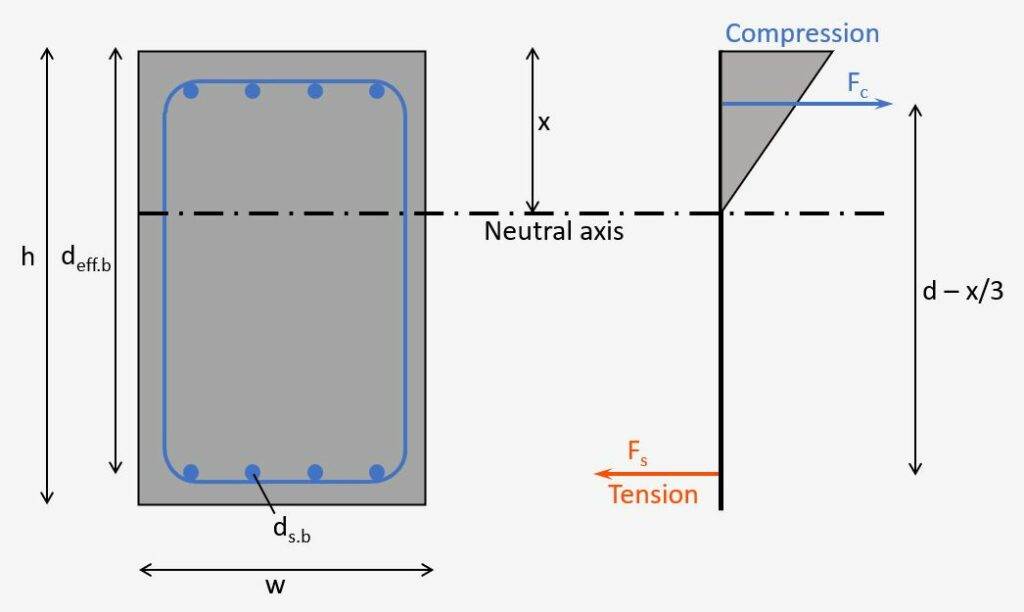
We’ll find the depth of the neutral axis by equilibrium of the first moment of areas of the tension (steel) and compression (triangle). But don’t get confused by the triangle here. When calculating the static moment of the compression zone, we only need the area of it and the lever arm is x/2.
Equilibrium of the 1. moment of areas:
$$w \cdot x \cdot x/2 = \alpha \cdot A_{s.b} \cdot (d_{eff.b} – x)$$
Now, let’s solve that equation for x to get the height of the compression area:
$$x = \frac{\alpha \cdot A_{s.b}}{w} \cdot (-1 + \sqrt{1 + \frac{2 \cdot w \cdot d_{eff.b}}{\alpha \cdot A_{s.b}}}) = 148 mm$$
3. Then, as the last step, the moment of inertia of the cracked section:
$$I_a = \frac{w \cdot x^3}{12} + w \cdot x \cdot (x/2)^2 + \alpha \cdot A_{s.t} \cdot (d_{eff.b} – x)^2$$
$$I_a = \frac{w \cdot x^3}{3} + \alpha \cdot A_{s.t} \cdot (d_{eff.b} – x)^2 = 1.072 \cdot 10^9 mm^4$$
Conclusion
The cracked moment of inertia is used for example in the design of reinforced concrete beams. You can find a step-by-step tutorial here:
Or in when verifying the crack width of flat slabs. 👇👇

![Shear Verification Without Shear Reinforcement [Eurocode]](https://www.structuralbasics.com/wp-content/uploads/2024/11/Shear-verification-without-shear-reinforcement-768x439.jpg)