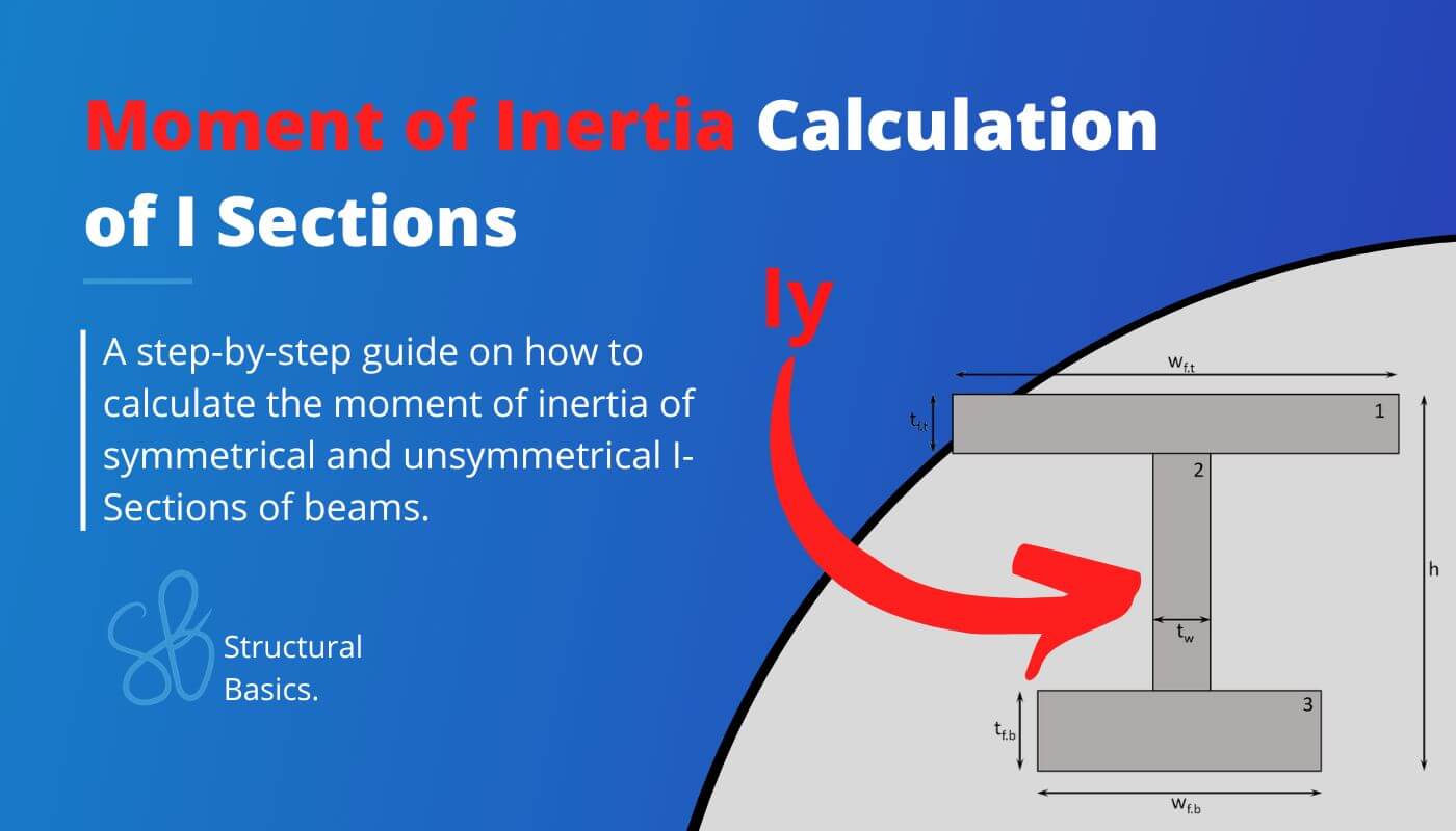
Moment of Inertia of I Beam: Calculation Example
Are you an engineer, student, or someone who is looking to understand better how the moment of inertia of an I Beam is calculated? 🙋♂️🙋♂️
The moment of inertia is a crucial parameter in calculating the bending stresses to verify structural objects such as beams, columns and slabs.
By understanding the calculation of the moment of inertia, you are one step closer to designing an I- or H-Beam. 🔥🔥
In this beginner’s guide, we’ll walk you through the process of determining the moment of inertia of an I Section, step-by-step.
Alright, let’s get started. 🚀🚀
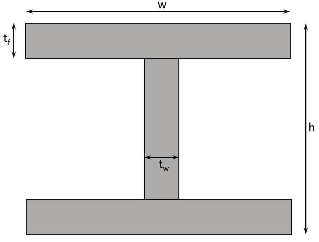
The Moment of Inertia of Symmetrical I Section
The short way is to just use the formula for a symmetrical I Section (strong axis). 👇👇
$$I_y = \frac{w \cdot h^3}{12} – \frac{(w-t_w) \cdot (h-2\cdot t_f)^3}{12}$$
You can check out more moment of inertia formulas in this blog post. 👈👈
But if you want to know how that formula comes together or how to calculate the moment of inertia of an unsymmetrical i section, then stick with us. 👍👍
Basically, the formula calculates the moment of inertia of a rectangular section with dimensions w x h and then subtracts the 2 “holes” left and right of the web.
OK, this might sound confusing, so let’s look at a picture. 🖼️🖼️
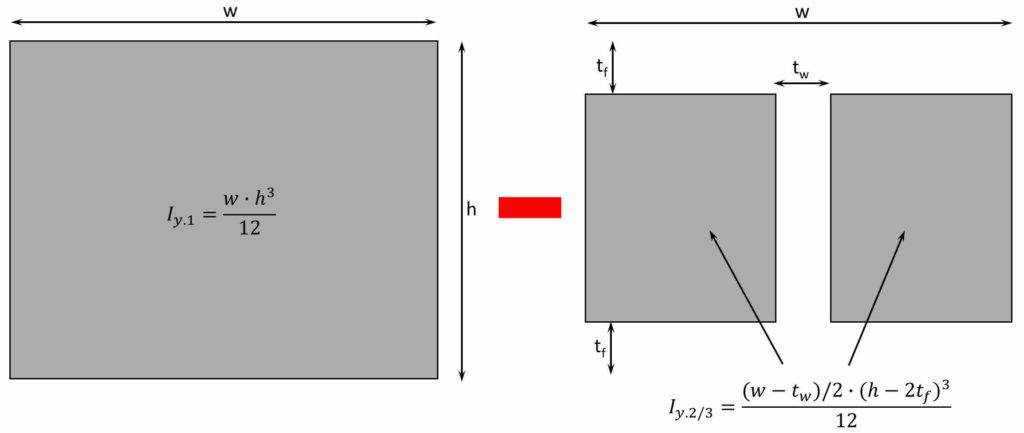
$$I_y = I_{y.1} – I_{y.2} – I_{y.3}$$
$$I_y = \frac{w \cdot h^3}{12} – \frac{(w-t_w)/2 \cdot (h-2\cdot t_f)^3}{12} – \frac{(w-t_w)/2 \cdot (h-2\cdot t_f)^3}{12}$$
$$I_y = \frac{w \cdot h^3}{12} – \frac{(w-t_w) \cdot (h-2\cdot t_f)^3}{12}$$
Now, let’s use some real dimensions and calculate the moment of inertia.
$t_{f}$ = 20mm
$h$ = 200mm
$w$ = 200mm
$t_w$ = 16mm
We insert these values into our formula. ⬇️⬇️
$$I_y = \frac{200mm \cdot (200mm)^3}{12} – \frac{(200mm-16mm) \cdot (200mm-2 \cdot 20mm)^3}{12} = 7.05 \cdot 10^7 mm^4$$
OK, this was the easy part – symmetrical i beams. Now we’re going to calculate the moment of inertia for an unsymmetrical i section. 👇👇
And btw, if you need us to also include the moment of inertia calculation of the weak axis, then let us know in the comments below. 📝📝
The Moment of Inertia of Unsymmetrical I Section
The Moment of inertia of an unsymmetrical i section is not as straightforward as for a symmetrical profile.
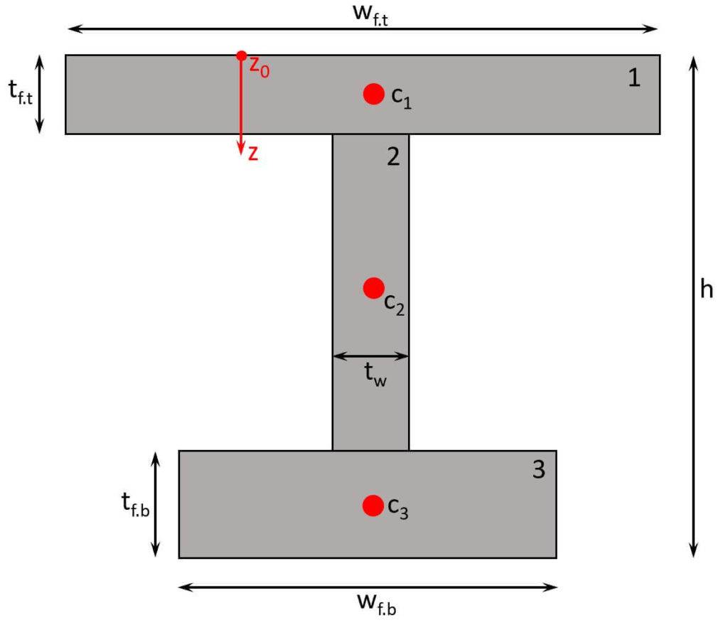
But we’ll explain it as practical as possible with the example section below. ⬇️⬇️
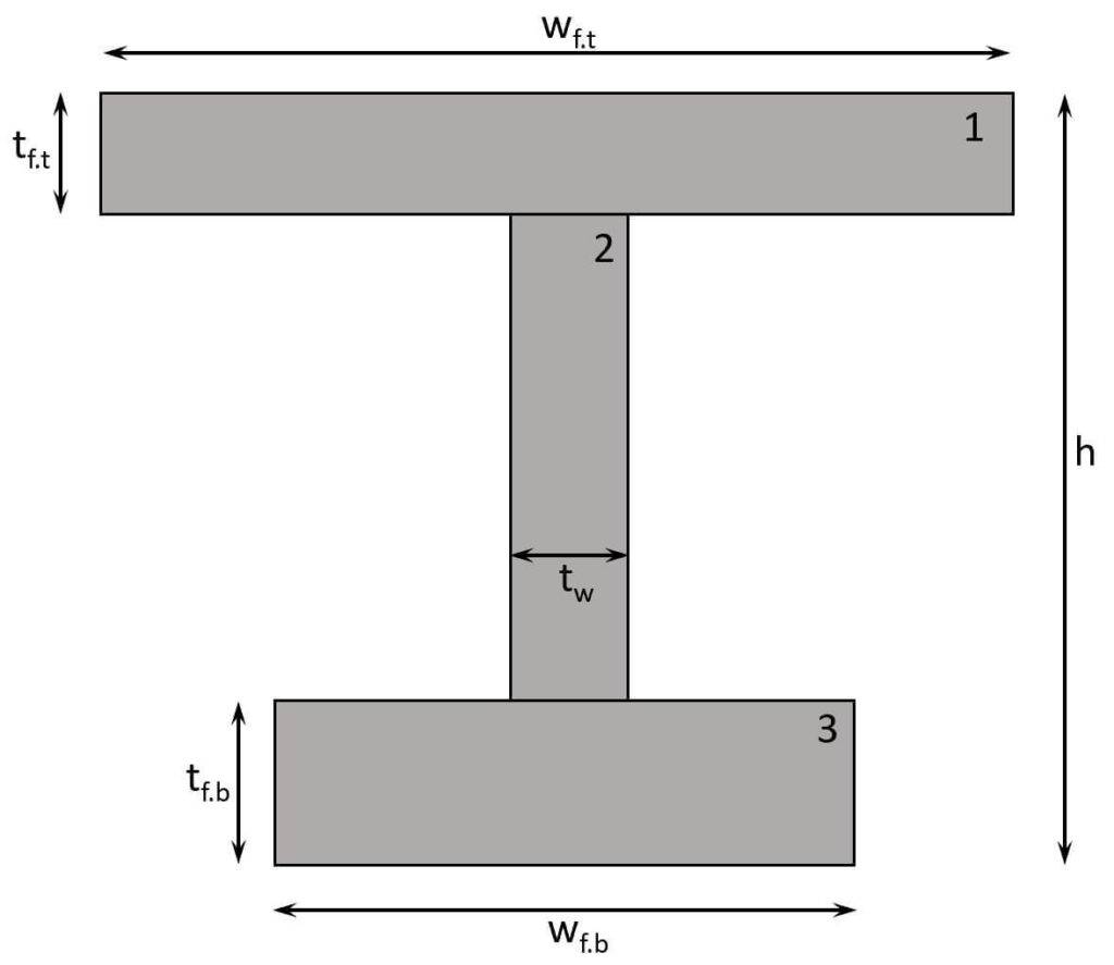
$t_{f.t}$ = 10mm
$t_{f.b}$ = 15mm
$h$ = 200mm
$w_{f.t}$ = 200mm
$w_{f.b}$ = 150mm
$t_w$ = 9mm
The easier way to calculate the moment of inertia is by using parallel-axes theorem which we are also using in this post. If you are interested in the more advanced method, then check out this article.
Parallel-Axes Theorem
$$I = \sum_0^n I_{0.n} + A_n \cdot x^2$$
With,
n = the number of “parts” the cross-section is split up (n=2 in the picture below)
$I_{0.n}$ = the moment of inertia of the part n of the cross-section concerning its center axis
$A_n$ = the area of the part
x = the distance from the center of the part n to the center axis
Now, there’s a simple step-by-step procedure that we can follow to calculate the moment of inertia of an i beam with the parallel-axes theorem. 👍👍
Procedure:
- Split the (Cross-) Section into its parts (see picture above – parts 1, 2, 3).
- Find the centroid of each part (see picture below).
- Calculate the area of each part.
- Calculate the moment of inertia of each part.
- Use to parallel-axes theorem to calculate the moment of inertia of the i section.
Now, let’s follow this step-by-step procedure.
Step #1
The section is split up into 3 parts, as you can see in the picture above.
Step #2
The centroid of each needs to be found now. First, let’s draw them into the section.
You can read more in detail about the centroid calculation here.
Centroid of part 1
$$z_{c.1} = \frac{t_{f.t}}{2} = \frac{10mm}{2} = 5mm$$
Centroid of part 2
$$z_{c.2} = t_{f.t} + \frac{h-t_{f.t}-t_{t.b}}{2} = 10mm + \frac{200mm – 10mm – 15mm}{2} = 97.5mm$$
Centroid of part 3
$$z_{c.3} = h – t_{f.b} + \frac{t_{t.b}}{2} = 200mm – 15mm + \frac{15mm}{2} = 192.5mm$$
Step #3
We now calculate the area of each part.
Area of part 1
$$A_1 = t_{f.t} \cdot w_{f.t} = 10mm \cdot 200mm = 2000mm^2$$
Area of part 2
$$A_2 = t_{w} \cdot (h-t_{f.t}-t_{t.b}) = 9mm \cdot (200mm-10mm-15mm) = 1575mm^2$$
Area of part 3
$$A_3 = t_{f.b} \cdot w_{f.b} = 15mm \cdot 150mm = 2250mm^2$$
Step #4
Calculation of moment of inertia of parts 1, 2 and 3.
Moment of inertia part 1
$$I_{0.1} = \frac{w_{f.t} \cdot t_{f.t}^3}{12} = \frac{200mm \cdot (10mm)^3}{12} = 16666.7 mm^4$$
Moment of inertia part 2
$$I_{0.2} = \frac{t_{w} \cdot (h-t_{f.t}-t_{f.b})^3}{12} = \frac{9mm \cdot (200mm – 10mm – 15mm)^3}{12} = 4.02 \cdot 10^6 mm^4$$
Moment of inertia part 3
$$I_{0.3} = \frac{w_{f.b} \cdot t_{f.b}^3}{12} = \frac{150mm \cdot (15mm)^3}{12} = 42187.5 mm^4$$
Step #5
Finally, we use all of those results and insert them into the parallel-axes theorem.
$$I = \sum_0^n I_{0.n} + A_n \cdot x^2$$
$$I = I_{0.1} + A_1 \cdot z_{c.1}^2 + I_{0.2} + A_2 \cdot z_{c.2}^2 + I_{0.3} + A_3 \cdot z_{c.3}^2$$
$$I = 16666.7 mm^4 + 2000mm^2 \cdot (5mm)^2 + 4.02 \cdot 10^6 mm^4 + 1575mm^2 \cdot (97.5mm)^2$$
$$ + 42187.5 mm^4 +2250mm^2 \cdot (192.5mm)^2$$
$$I = 1.02 \cdot 10^8 mm^4$$
💡💡 Bonus Tip: If you need to calculate the moment of inertia of a complex I Section or any Section in general, then you can use a Tool like Rhino where you draw the section. With a few simple steps, you can then determine its centroid dimensions. 💡💡
Here’s a guide how to use Rhino to automatically calculate the moment of inertia.
Let us know in the comments below if you want us to add the moment of inertia calculation for the weak axis as well. ✍️✍️
What Is The Moment of Inertia?
The moment of inertia is a key parameter used in the structural design of beams and other structural elements subject to bending. It’s used to calculate the bending stresses that a structural element will experience when subjected to a load.
In easier terms, it’s a measure of how the material of a structural element is distributed with respect to the axis of rotation, like, for example, the centerline of a beam.
Conclusion
Now, that you got an understanding of how to calculate the moment of inertia of an i beam, you can learn about section modulus and cross-sectional area, because these parameters are also cross-sectional properties and used in engineering.
If you want to learn where the moment of inertia is actually used in structural engineering, then check out the following articles.📖📖
I hope that this article helped you understand the moment of inertia calculation and how to go further from here. In case you still have questions.
Let us know in the comments below. ✍️✍️
![9+ Polar Moment Of Inertia Formulas [2026]](https://www.structuralbasics.com/wp-content/uploads/2023/09/2nd-polar-moment-of-inertia-formulas-768x439.jpg)
![Moment of Inertia Calculation [2026]](https://www.structuralbasics.com/wp-content/uploads/2023/01/Moment-of-Inertia-calculation-768x439.jpg)
![How to Calculate The Cross Sectional Area? [A Beginner’s Guide]](https://www.structuralbasics.com/wp-content/uploads/2023/01/how-to-calculate-the-cross-sectional-area-768x439.jpg)
![K-Truss [All YOU Need To Know]](https://www.structuralbasics.com/wp-content/uploads/2023/02/K-Truss-768x439.jpg)