Supports: Different Types & How To Calculate Their Reactions
The Golden Gate Bridge, the Eiffel Tower and a boring concrete slab above your head have a few things in common.
One of those things is, that they are all structurally sufficiently supported – quite in different ways and dimensions, but all structures would collapse if they weren’t.
Okay, those are extreme examples, BUT: all structural supports – big and small structures – follow the same principles.
So in this article, we’ll discover, what structural supports are, what different support types are used and how to calculate the reaction forces of supports.
Let’s get started.
🙋♂️ What Are (Structural) Supports?
Supports in structures make sure that the loads that are acting on the supported structure are getting transferred to the next element, like foundation, column, etc.
Let’s have a look at an example.

The following things can be said about the wooden “beams” of the bench and its supports
- The static system of the wood beams is a simply supported beam
- The loads on the beam are self-weight of the beams and people (dead load) and snow load
- Those loads travel through the beam and to the supports
- The supports are a roller and pin support (more on that later in the article)
- The support forces equal the external loads (more on that later)
- The support forces are transferred to the next structure (the steel plate/bracket)
Now, the supports need to be able to take the support force. If the steel plates (supports) are not able to take the support force, the structure (bench) collapses.
Later in this article, you’ll learn how to calculate the support forces and what different types are used in structural engineering.
Everday Example
Most elements on this earth don’t move because they’re somehow structurally supported.
Let’s look at an example.

This apple, for instance, is sufficiently supported by the table and that’s why it’s not moving somewhere.
The word sufficiently plays a role here.
Because as soon as the external loads acting on an element are bigger than the reaction forces that the support can take, the supports will fail, or the element will rotate or “slide away”.
In the example of our apple, we only have to apply a small load on the side of the apple, and it will slide away.
In that scenario, the load is bigger than what the horizontal reaction forces can take.
🙆 Different Types Of Supports
Every structure requires different supports, as the choice of support has a big influence on the behaviour of the structure.
Due to supports, a structure can be restraint, flexible, rigid – not only because of the support, but it has a big influence.
For example, the rigid frame as the name already says is quite rigid compared to the 2-hinge-frame which allows for much more deformation and deflection.
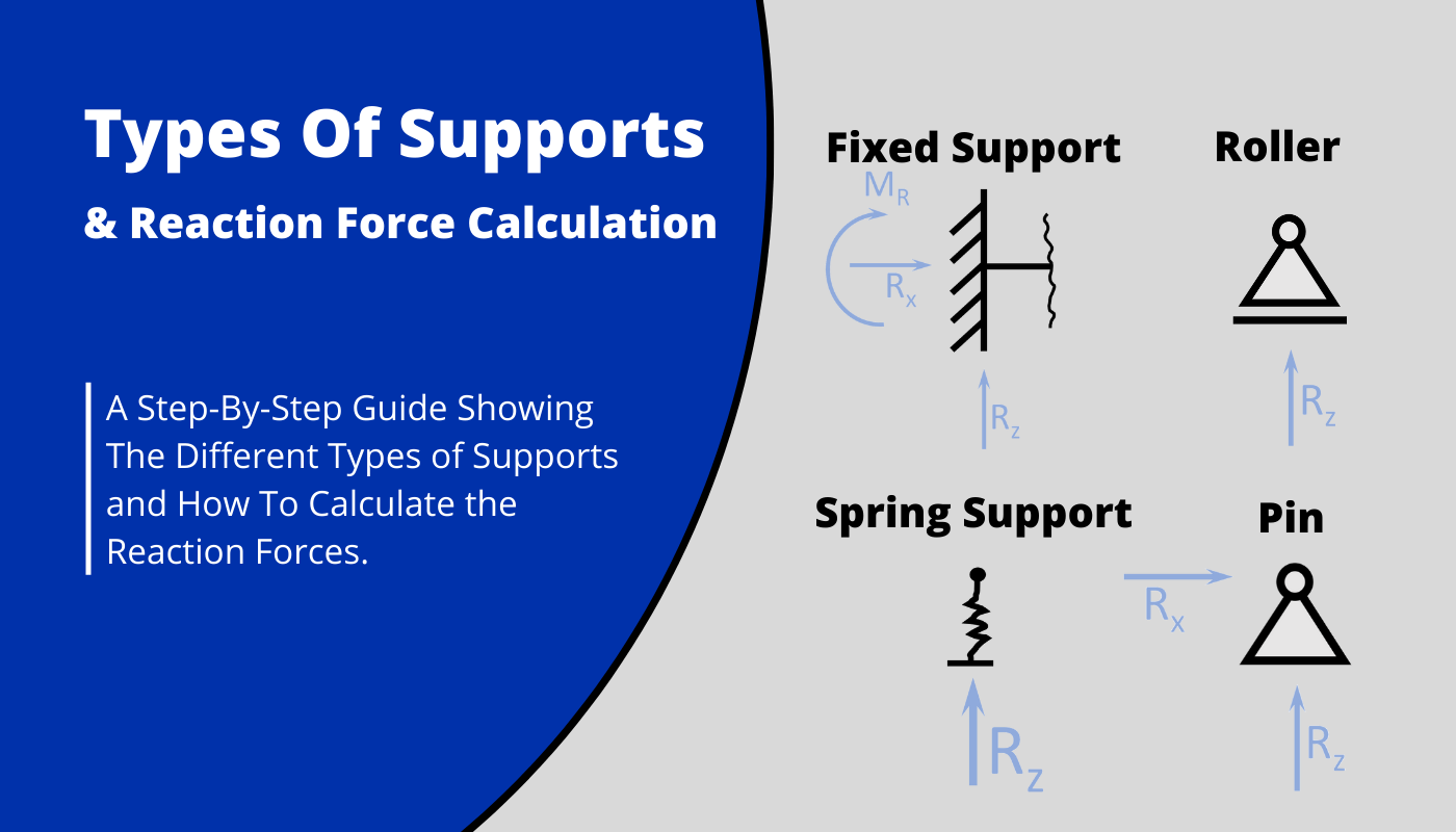
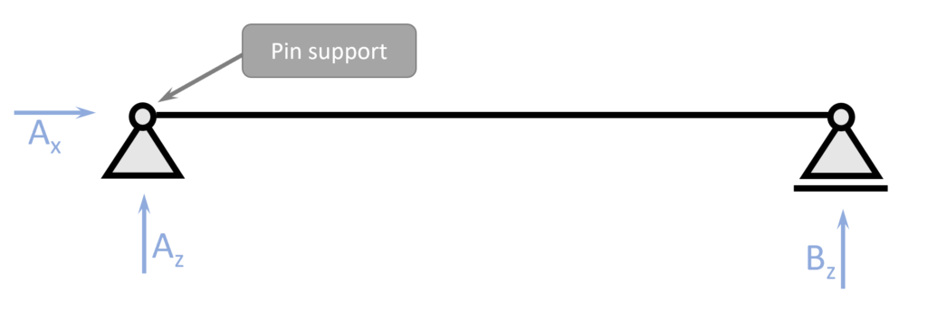
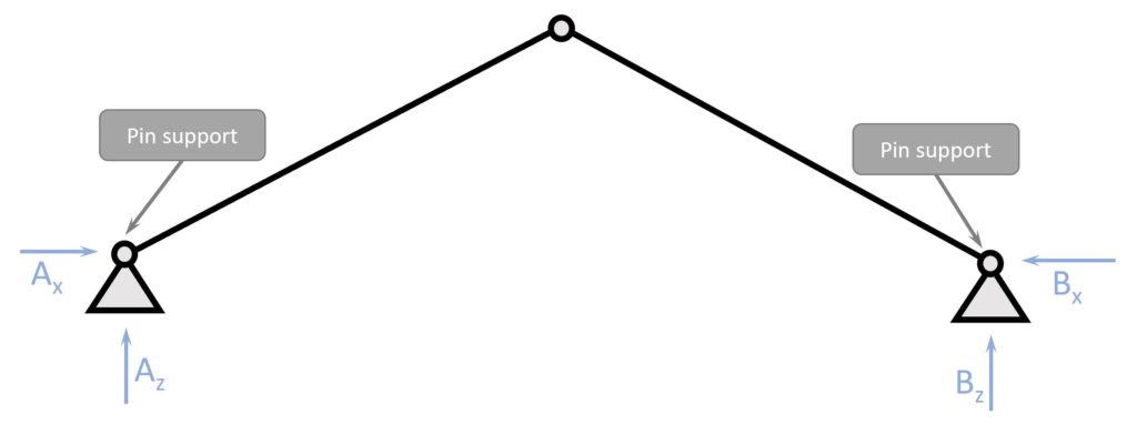
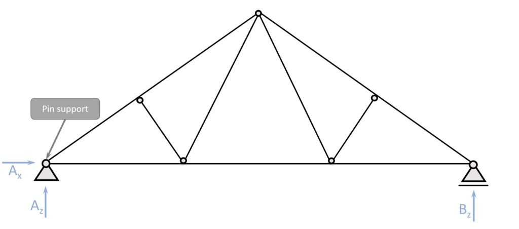
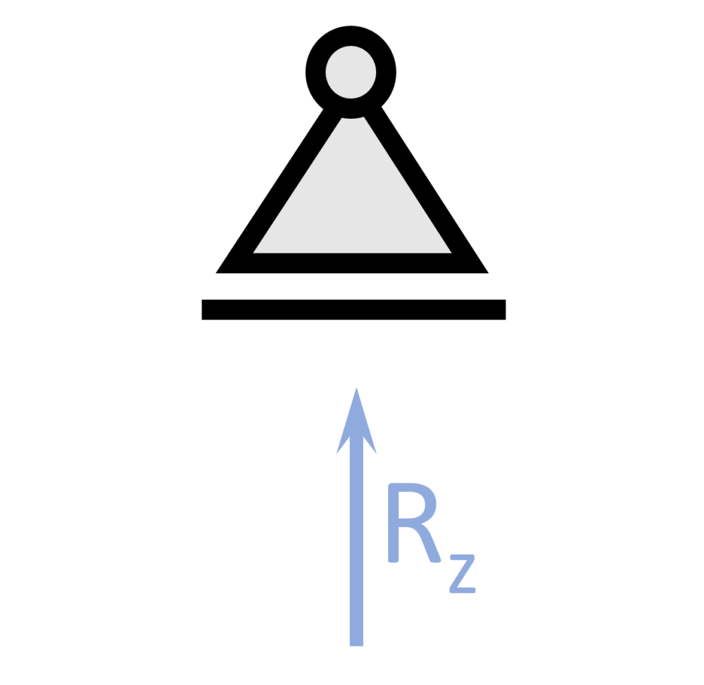
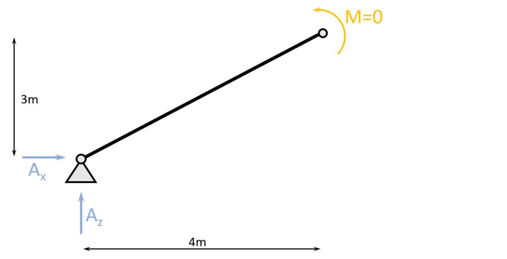
1. Pin Support
Pin Support
Pinned supports allow for 2 Reaction Forces, a horizontal and a vertical, while they allow for rotation. This means that the Moment at the pin support is 0. But be careful here. This is only the case if the hinge is also used, and NOT if there is a continuous beam.

Static Systems
Simply supported beam, Columns, Continuous beams
Reactions
Horizontal $R_x$, Vertical $R_z$
Examples
Bridge bearings, Wood beam supports, etc.
Let’s dive a bit deeper and look at Static System examples where pin supports are used.
Examples
Simply Supported Beam (1 pin support)
Wood Rafter Roof (2 pin supports)
Wood Truss Roof (1 pin support)
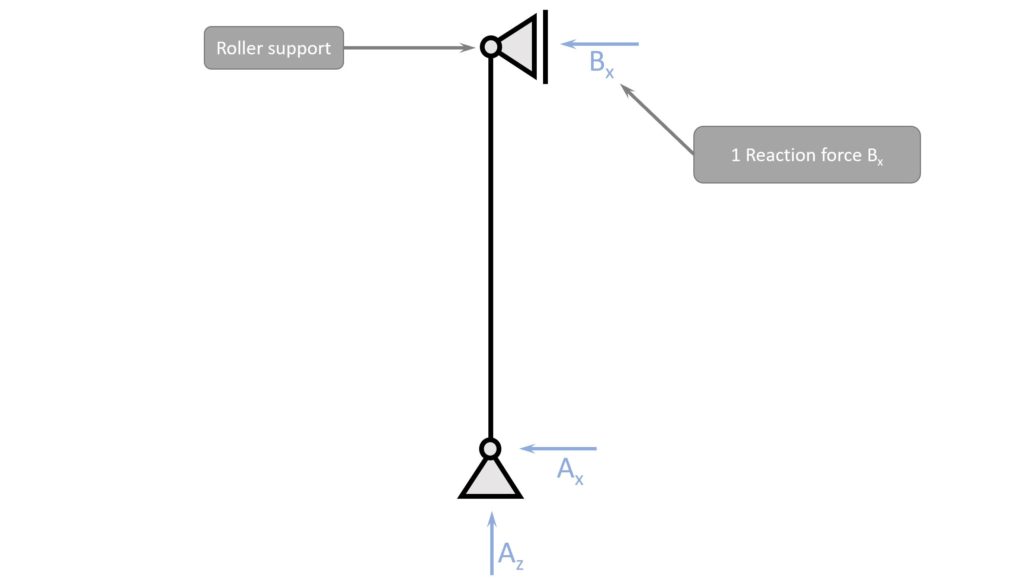
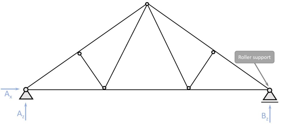
2. Roller Support
Roller Support
Roller supports allow for Only 1 Reaction Force, a horizontal OR a vertical, while they also allow for rotation. The Moment at the roller support is 0. In a simply supported beam, the roller support has a Vertical Reaction force, while in a column the reaction is a horizontal force. We’ll show examples of that later.
Static Systems
Simply supported beam, Columns, Continuous beams
Reactions
Horizontal $R_x$ OR (❗) Vertical $R_z$
Examples
Bridge bearings, Wood beam supports, etc.
Let’s dive a bit deeper and look at Static System examples where roller supports are used.
Examples
Simply Supported Beam (1 roller support)

Column (1 roller support)
Continuous Beam (2+ roller supports)
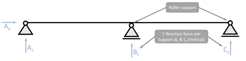
❗Note that the beam at the middle support takes up bending moments.
In the Info Box we learned that the roller support doesn’t take bending moments and that is true.
BUT the beam isn’t split up in 2 parts and connected to each other by the hinge of the roller support. It’s one continuous piece, and can therefore take bending moments.
Wood Truss Roof (1 roller support)
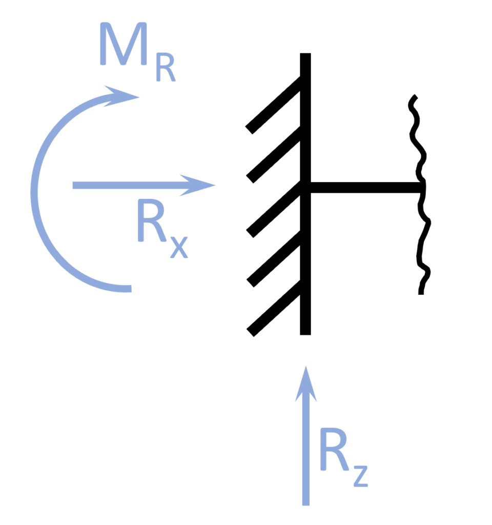
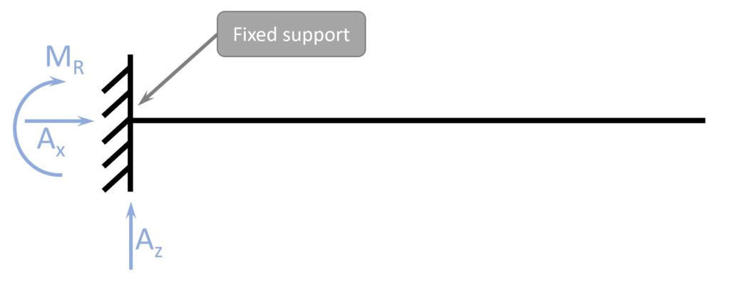
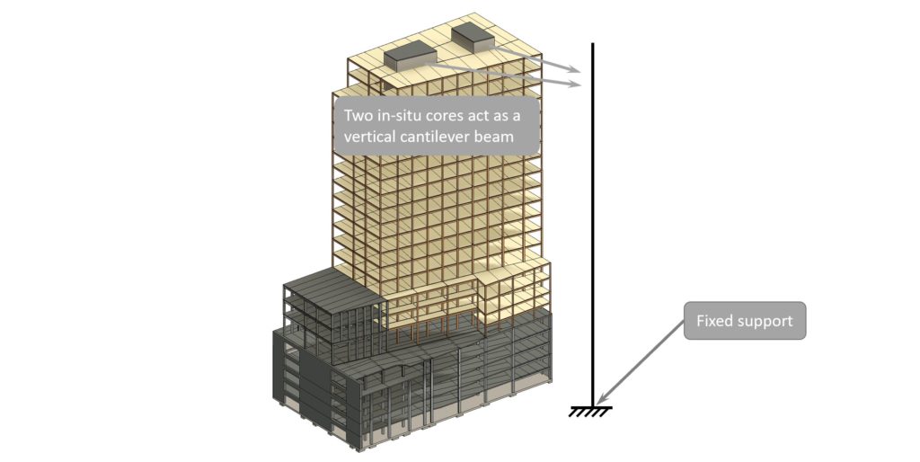
3. Fixed Support
Fixed Support
Fixed supports allow for 3 Reaction Forces, a horizontal and vertical reaction force and a moment. The fixed support is therefore not allowing for free rotation. The fixed support is often used to increase robustness, get unsupported spans like roof overhangs or to limit the deformations of a structure.
Static Systems
Cantilever beam, Rigid frame
Reactions
Horizontal $R_x$, Vertical $R_z$ and Moment $M_R$
Examples
Cantilever balconies, Steel frame structures, in-situ concrete support, etc.
Let’s dive a bit deeper and look at Static System examples where fixed supports are used.
Examples
Cantilever Beam (1 fixed support)
Rigid frame (2 fixed supports)

Concrete Core of a High-rise Building (1 fixed support) – Vertical Cantilever
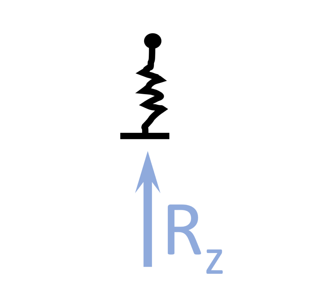
4. Spring Support
Spring Support
Spring supports allow for 1 Reaction Force, however the support could be also additionally restraint in another direction or rotation. Also, another spring could be added if the structure requires that. In the example of the cable stayed bridge (down below) the spring support behaves similar to a roller support. The main difference is that the spring support lets the deck (deflect) and the roller doesn’t. Therefore, the vertical reaction force of the spring support is smaller compared to the one from a roller support.
Static Systems
Beam supported by cables, beam/column supported by foundation/earth
Reactions
Horizontal $R_x$, Vertical $R_z$ and Moment $M_R$
Examples
Cable stayed bridge (cables), High-Rise in-situ concrete core supported by (pile) foundation
Let’s dive a bit deeper and look at Static System examples where Spring Supports are used.
Examples
Cable Stayed Bridge
To calculate the bending moment in a cable stayed bridge deck, the cables which support the deck can be modelled as a spring support with the spring stiffness of the corresponding cable.
2D Sketch of Cable Stayed Bridge
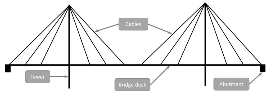
Static System of the bridge deck (Approximation)

For a very first approximation, the cables can be modelled as Spring supports.
Now that we showed all the different types of supports and explained them by a lot of different examples – the next step is to calculate the reaction forces.
📖 How To Calculate Support Reaction Forces
To calculate reaction forces, we first need to know whether the structure is statically determinate or indeterminate.
For statically determinate structures, the reaction forces can be calculated by the 3 Equilibrium equations.
- $\sum H = 0$: The sum of all horizontal external loads and reaction forces equals 0.
- $\sum V = 0$: The sum of all vertical external loads and reaction forces equals 0.
- $\sum M = 0$: The sum of all Moments equal 0.
For statically indeterminate structures, more advanced methods need to be used to calculate the reaction forces, such as the Force Method.
In this tutorial, we’ll only look at statically determinate structures.
Example – Rafter Roof

The chosen static system has 2 pinned supports A & B. Each of them have a horizontal and a vertical reaction force.
2 external forces Q – vertical point load – and P – horizontal point load – act on the static system.
Q = 2 kN
P = 3 kN
Let’s start by defining the 3 equilibrium equations.
$\sum H = 0: A_x – B_x – P = 0$
$\sum V = 0: A_z + B_z – Q = 0$
The Moment in a specific point of a static system due to an external load is calculated as
Load $\cdot$ Distance to point.
We are choosing to do the Moment equilibrium in point A.
$\sum M = 0: B_z \cdot 8m + P \cdot 3m – Q \cdot 4m = 0$
The only equation where we just have 1 Unknown is the Moment equilibrium. Therefore we solve this equation first.
$B_z = \frac{Q \cdot 4m – P \cdot 3m}{8m} = \frac{2 kN \cdot 4m – 3 kN \cdot 3m}{8m} = -0.125kN$
From here we can calculate $A_z$
$\sum V = A_z + B_z – Q = 0$
$A_z = 0.125 kN + 2 kN = 2.125 kN$
To get the 2 horizontal reaction forces $A_h$ and $A_v$ we define another moment equilibrium in the top hinge but only considering the left beam.
$\sum M = 0: A_x \cdot 3m – A_z \cdot 4m = 0$
$A_x = 2.125kN \cdot \frac{4m}{3m} = 2.83 kN$
$A_x$ is inserted it in the horizontal equilibrium equation to get $B_x$.
Horizontal equilibrium equation
$\sum H = 0: A_x – B_x – P = 0$
$A_x – B_x – P = 0$
$B_x = 2.83 kN – P = -0.17kN$
We now successfully calculated all 4 support reaction forces.
$A_z = 2.125kN$
$A_x = 2.83kN$
$B_z = -0.125kN$
$B_x = -0.17kN$
Now, once all reaction forces are calculated, we can go ahead and calculate the internal forces of the members as we did in these articles
After the determination of the internal forces, the elements can be designed as we did in these following articles.
But now I would like to know from you, have you understood the concept of 3 Equilibrium equations?
Because I remember, it took me almost my entire 1st semester to really understand how to calculate moments and divide forces into horizontal and vertical components.
So let us know in the comments✍️
![Queen Post Trusses Explained! [2026]](https://www.structuralbasics.com/wp-content/uploads/2023/02/Queen-post-truss-768x439.jpg)
![The Fink Truss [All YOU Need to Know]](https://www.structuralbasics.com/wp-content/uploads/2022/12/Fink-truss-768x439.jpg)
![Understand Bending Moments [Everything YOU Need To Know – 2026]](https://www.structuralbasics.com/wp-content/uploads/2023/05/Bending-moment-768x439.jpg)
![Howe Truss [A Structural Guide]](https://www.structuralbasics.com/wp-content/uploads/2022/12/Howe-truss-768x439.jpg)