Internal forces: Examples & Sign Convention
Calculating the internal forces in structural elements, such as beams for different loading scenarios, is probably one of the things in structural engineering that we do throughout our studies and also careers later on.
And at any point of our career it’s very important to know how to derive and calculate the internal forces (moments, normal & shear forces).
So in this article, we’ll show, what internal forces are, its sign convention and examples on how to calculate internal forces for specific static systems.
But now, let’s get started.
↘️ What are internal forces?
Structural elements must resist forces within itself – the so-called internal forces – which are produced by external forces like dead load, snow load, wind load, etc.
If the structural elements don’t resist those internal forces, the elements break/fail.
In general, there is 3 different internal forces
- Normal force N(x)
- Shear force and Q(x)
- Moment M(x)
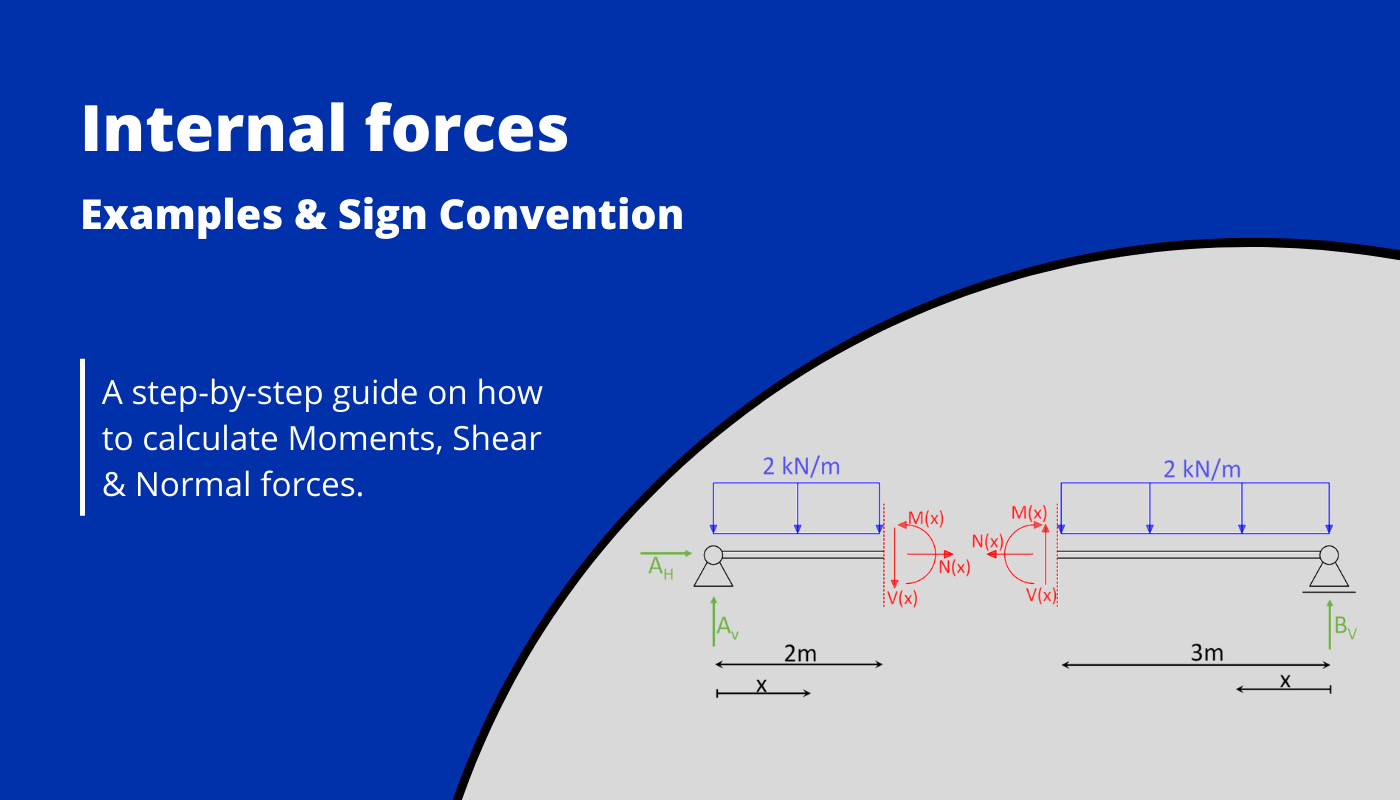
The Cut of the beam and the directions of the forces are explained later on in this article. For now the image above is a good introduction of the Moment M, Normal force N and Shear force V.
Moment
The Moment or also called bending Moment happens when a structural element bends. This can happen by forces or Moments. The unit is Kilonewton meter [kNm].
A positive Moment (+) leads to compression in the top part of the Cross-section of the structural member (e.g. beam) and tension in the bottom, while a negative Moment (-) turns this into compression in the bottom and tension in the top part of the Cross-section.
Normal force
The Normal force N acts in the axis of the beam. The unit is Kilonewton [kN].
A negative Normal force (-) leads to compression in the structural member, while a positive Normal force (+) leads to tension in the member.
Note that for columns the normal force acts also in the column axis, but instead of being horizontal, the Normal force acts vertical.
Shear force
The Shear force V acts perpendicular to the beam axis. The unit is Kilonewton [kN].
The best definition of shear I have ever read comes from J. E. Gordon from his book Structures: Or Why Things Don’t Fall Down. I have done a whole article about the best takeaways of the book, and you can read about his explanation of Shear here.
➕ Sign Convention
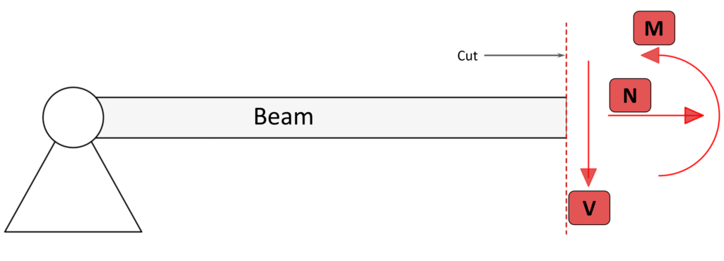
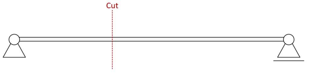
To know the forces & moments at a specific point in a beam, a cut can be made at that point perpendicular to its axis. The beam is separated into two parts and the internal forces are visualized.
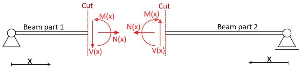
The sign convention is implemented to know which force is positive and which force is negative.
💡 The Normal forces, Shear forces and Moments on both sides are equal in magnitude but are applied in opposite directions!
For example, the Shear force V(x) at beam cut 1 is applied downwards⬇️, while the Shear force V(x) at beam cut 2 is applied upwards⬆️. The same goes for the Moments M(x) ↪️↩️ and Normal forces N(x) ➡️⬅️.
❗Note that there is a variety of different sign conventions due to different coordinate systems.
I was taught to use the force direction like in the picture above, but I am curious to know if in any other country you apply the forces in a different direction. Let us know in the comments below✏️.
📄 Step-by-step procedure to calculate internal forces
Follow this step-by-step guide to calculate Moments, Normal & Shear forces for statically determinate structures. We’ll apply the steps in the examples later on.
- Calculate the reaction forces
- Cut the structural member perpendicular to its axis & Visualize internal forces on both cuts
- Calculate internal forces from 3 equilibrium equations $\sum H$, $\sum V$ and $\sum M$
Alright, so let’s apply those 3 steps to some examples.
🧮 Examples
Simply supported beam with Line load
Parameters:
- $q = 2 kN/m$
- $l = 5m$
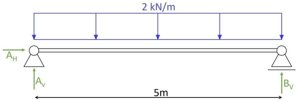
1. Calculate Reaction forces
3 equilibrium equations:
- Vertical equilibrium: $\sum V = 0: 2 kN/m \cdot 5m – A_V – B_V = 0$
- Horizontal equilibrium: $\sum H = 0: A_H = 0$
- Moment equilibrium in A: $\sum M = 0: 2 kN/m \cdot \frac{(5m)^2}{2} – B_v \cdot 5m = 0$
Due to symmetry, $A_V = B_V$ and the vertical equilibrium equation can be solved to
$A_V = B_V = 5 kN$
The horizontal equilibrium shows that the horizontal force $A_H = 0$.
In the Moment equilibrium equation, it can be checked if the results obtained for $A_V$ and $B_V$ are correct.
$2 kN/m \cdot \frac{(5m)^2}{2} – 5 kN/m \cdot 5m = 25 kNm – 25 kNm = 0$ 👍
2. Cut the structural member perpendicular to its axis & Visualize internal forces on both cuts
Cut at 2 m from left support.
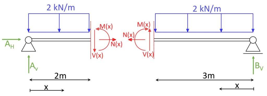
Now, based on the reaction forces the internal forces can be calculated in accordance to a variable x or at specific points as in the picture (2m from left support).
3. Calculate internal forces from 3 equilibrium equations $\sum H$, $\sum V$ and $\sum M$
We first calculate the internal forces (Moment, Shear and Normal force) in dependence of the variable x. Later on we replace x with the value of 2 m and 3 m respectively.
3 equilibrium equations for left cut:
- Vertical equilibrium: $\sum V = 0: 2 kN/m \cdot x – A_V + V(x) = 0$
- Horizontal equilibrium: $\sum H = 0: A_H + N(x) = 0$
- Moment equilibrium at x: $\sum M = 0: M(x) + 2 kN/m \cdot \frac{(x)^2}{2} – A_V \cdot x = 0$
Because we already calculated the values of the reaction forces, we find the internal forces as:
- $V(x) = 5 kN – 2 kN/m \cdot x$
- $N(x) = 0$
- $M(x) = 5 kN \cdot x – 2 kN/m \cdot \frac{(x)^2}{2}$
Now we set x = 2m to get the internal forces at that specific point.
$V(2m) = 5 kN – 2 kN/m \cdot 2m = 1 kN $
$N(2m) = 0$
$M(2m) = 5 kN \cdot 2m – 2 kN/m \cdot \frac{(2m)^2}{2} = 10 kNm – 4 kNm = 6 kNm$
To double-check if the internal forces are calculated correctly, the same can be done for the right cut and the internal forces must equal those from the left cut.
3 equilibrium equations for right cut:
- Vertical equilibrium: $\sum V = 0: 2 kN/m \cdot x – B_V – V(x) = 0$
- Horizontal equilibrium: $\sum H = 0: N(x) = 0$
- Moment equilibrium at x: $\sum M = 0: M(x) + 2 kN/m \cdot \frac{(x)^2}{2} – B_V \cdot x = 0$
Internal forces are found as:
- $V(x) = -5 kN + 2 kN/m \cdot x$
- $N(x) = 0$
- $M(x) = 5 kN \cdot x – 2 kN/m \cdot \frac{(x)^2}{2}$
Now we set x = 3m to get the internal forces at that specific point.
$V(3m) = -5 kN + 2 kN/m \cdot 3m = 1 kN $
$N(3m) = 0$
$M(3m) = 5 kN \cdot 3m – 2 kN/m \cdot \frac{(3m)^2}{2} = 15 kNm – 9 kNm = 6 kNm$
✔️ The internal forces at the left and right cut are equal and the internal forces of the simply supported beam are successfully calculated.
If you are new to structural design, then check out our design tutorials where you can learn how to use the calculated bending moments and shear forces to design structural elements such as
But now I would like to know from you, have you understood the concept of Bending moment, shear and normal force? Because I remember, it took me almost my entire 1st semester to really understand how to calculate moments. So let us know in the comments✍️, if you want more detailed posts and how you learned the concept of Moments.
![Howe Truss [A Structural Guide]](https://www.structuralbasics.com/wp-content/uploads/2022/12/Howe-truss-768x439.jpg)
![Gambrel Truss [A Structural Guide]](https://www.structuralbasics.com/wp-content/uploads/2023/02/Gambrel-truss-768x439.jpg)
![Understand Bending Moments [Everything YOU Need To Know – 2026]](https://www.structuralbasics.com/wp-content/uploads/2023/05/Bending-moment-768x439.jpg)
![The Pratt Truss Explained [2026]](https://www.structuralbasics.com/wp-content/uploads/2022/12/Pratt-truss-explained-768x439.jpg)