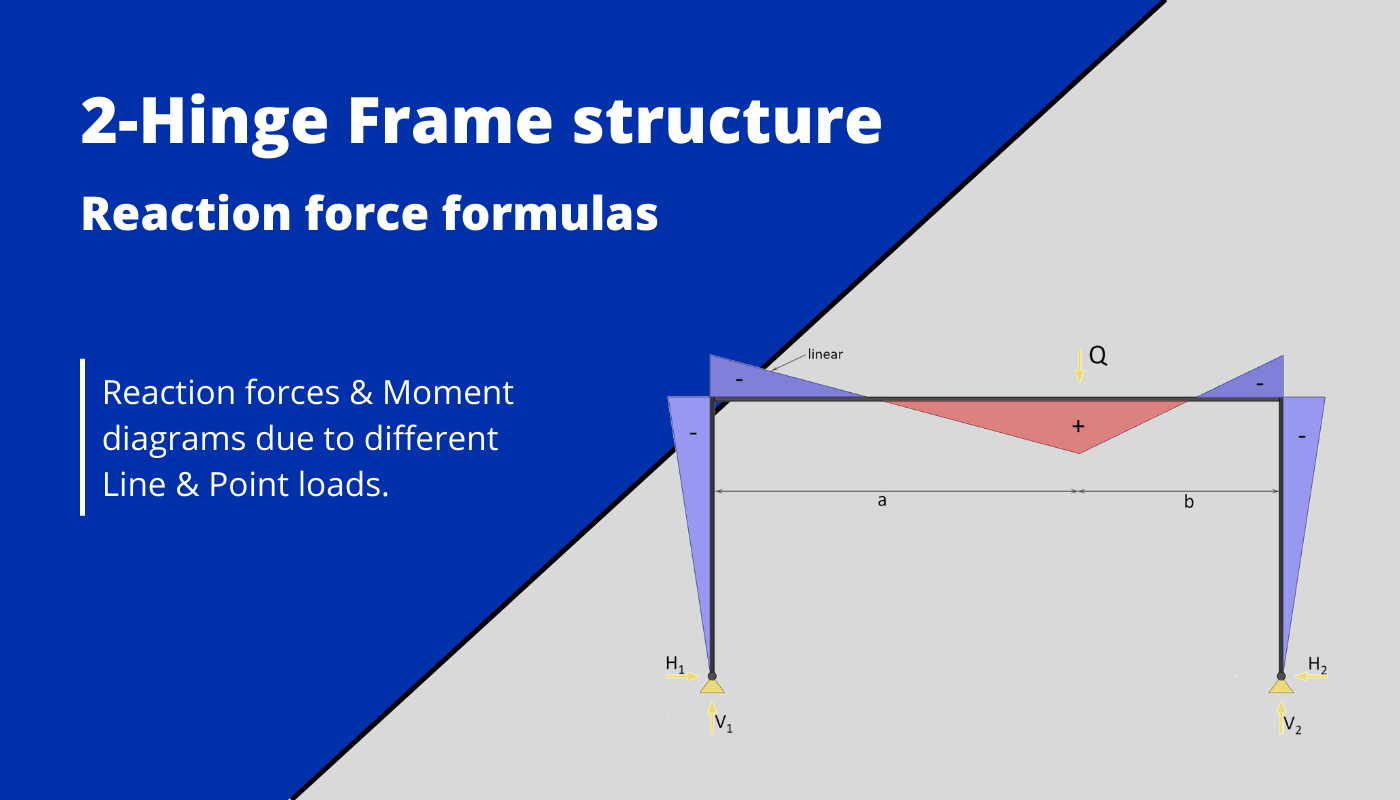
Two-hinge frame structure: Reaction force formulas – Different loads
Calculating bending moments, shear and reaction forces in structural elements – in this case frames with two hinged supports – for different loading scenarios, is probably one of the things in structural engineering that we do throughout our studies and also careers later on.
While it’s very important to know how to derive and calculate reaction and internal forces, the further we get in our studies, the more we can use frame moment and shear formulas.
In earlier articles, we already covered moment and shear force formulas and diagrams for:
- Simply supported beams
- Cantilever beams
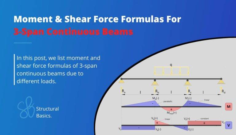
- 2 span continuous beams
- 3 span continuous beams
- 4 span continuous beams
In this article, we’ll show, the most important and easiest reaction force formulas for frames with 2 hinge supports due to different loading scenarios like UDL line loads, point loads and external moments.
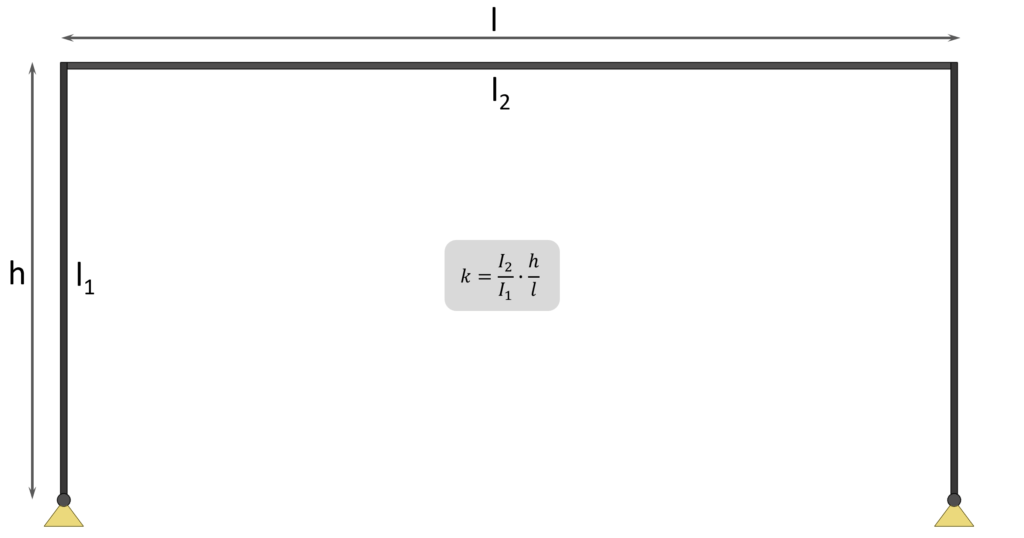
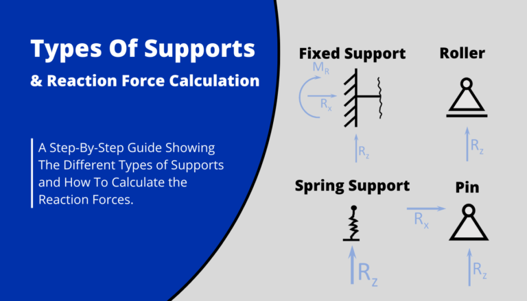
Before we start, some boundary conditions are set, such as that
- the 2 columns have the same Moment of inertia $I_1$ and a length of h
- the top beam has the Moment of inertia $I_2$ and a length of l
- the parameter k is defined as $\frac{I_2}{I_1} \cdot \frac{h}{l}$.
1. Uniformly distributed line load (UDL) on beam
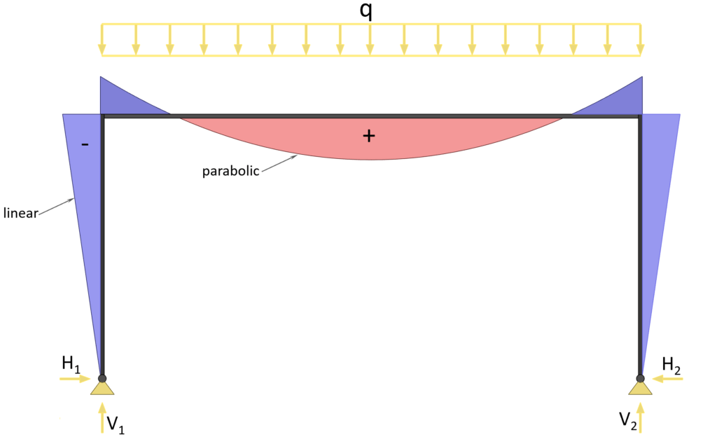
Horizontal reaction forces
$H_1 = H_2 = \frac{q \cdot l^2}{4\cdot h \cdot (2\cdot k + 3)}$
Vertical reaction forces
$V_1 = V_2 = \frac{q \cdot l}{2}$
2. Uniformly distributed load (UDL) on both columns
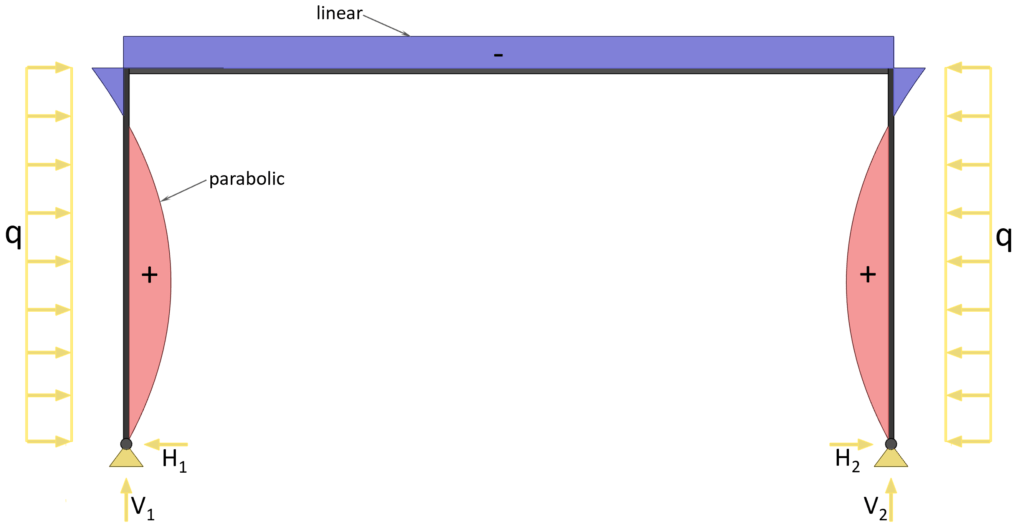
Horizontal reaction forces
$H_1 = H_2 = \frac{q \cdot h \cdot (3\cdot k + 6)}{8\cdot k + 12}$
Vertical reaction forces
$V_1 = V_2 = 0$
3. Uniformly distributed load (UDL) on 1 column
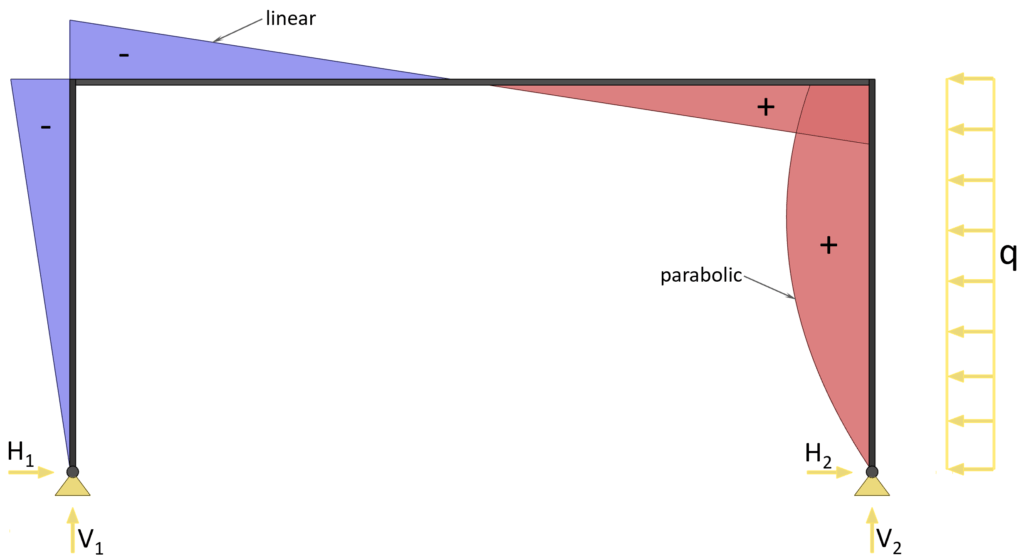
Horizontal reaction forces
$H_1 = \frac{q \cdot h \cdot (5\cdot k + 6)}{16\cdot k + 24}$
$H_2 = q \cdot h – \frac{q \cdot h \cdot (5\cdot k + 6)}{16\cdot k + 24}$
4. Point load on beam
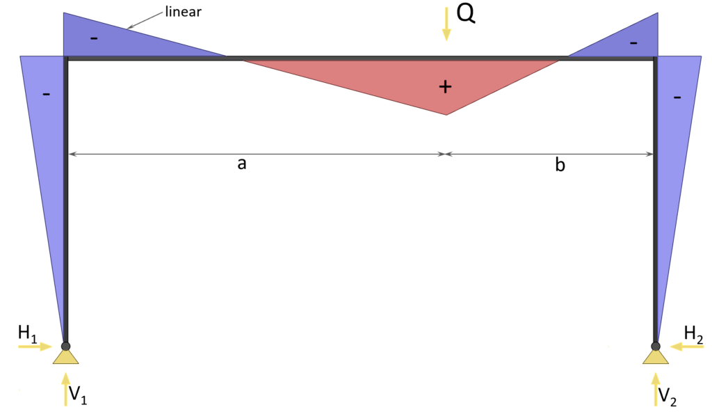
Horizontal reaction forces
$H_1 = H_2 = \frac{3 \cdot Q \cdot a \cdot b}{2\cdot h \cdot l \cdot (2\cdot k + 3}$
5. Point load on Column
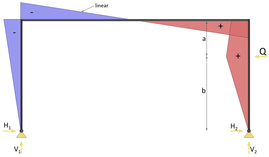
Horizontal reaction forces
$H_1 = 0.5 \cdot Q \cdot \frac{3 \cdot b \cdot h^2 \cdot (k+1) – b^3 \cdot k}{h^3\cdot (2 \cdot k +3)}$
$H_2 = Q- 0.5 \cdot Q \cdot \frac{3 \cdot b \cdot h^2 \cdot (k+1) – b^3 \cdot k}{h^3\cdot (2 \cdot k +3)}$
If you are new to structural design, then check out our design tutorials where you can learn how to use the calculated bending moments and shear forces to design structural elements such as
Do you miss any formulas for this 2 hinge frame that we forgot in this article? Let us know in the comments✍️
![K-Truss [All YOU Need To Know]](https://www.structuralbasics.com/wp-content/uploads/2023/02/K-Truss-768x439.jpg)
![Howe Truss [A Structural Guide]](https://www.structuralbasics.com/wp-content/uploads/2022/12/Howe-truss-768x439.jpg)