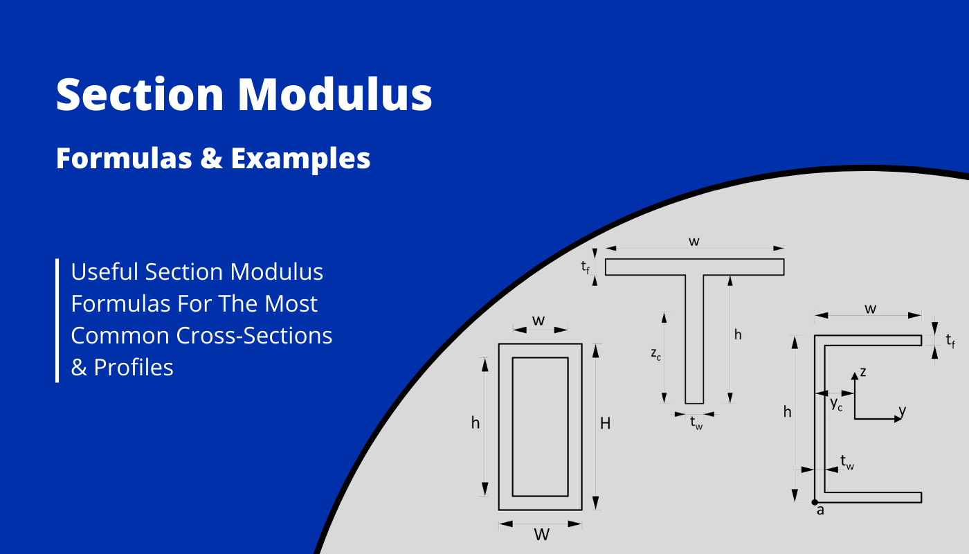
Section Modulus Formulas For Different Shapes {2026}
The section modulus is a property of an object that indicates how well the object can resist bending or deformation under external loading.
When an object has a different shape, it also has a different section modulus. In this blog post, we’ll cover section modulus formulas for different shapes, so you can calculate it more quickly.
Now, before we get started, always remember that the unit of the Section modulus is the third power of a length unit [$length^3$].
If you would like to use $mm$ in your calculation, then the unit of the Section modulus is $mm^3$.
But now, let’s get started. 🚀🚀
Section Modulus Formula
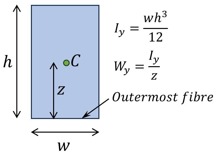
The section modulus W is calculated as moment of inertia I divided by the distance z from the neutral axis to the outermost fibre of the section.
$$W = \frac{I}{z}$$
What is the section modulus?
The section modulus is a cross-sectional geometric property of structural elements such as beams, columns, slabs, etc. and it is used to calculate stresses in cross-sections. In general, it can be said that the greater the dimensions of a cross-section under a given load, the greater the Section modulus and the smaller the bending stress.
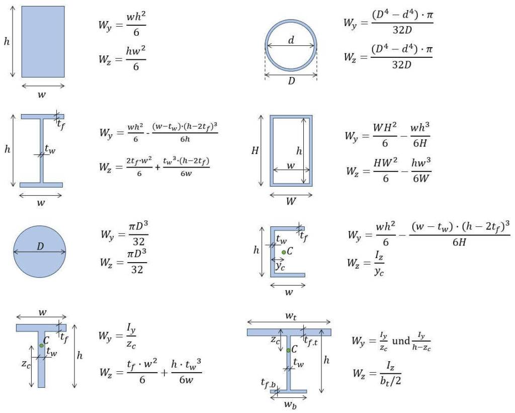
1. Section modulus – Rectangular shape/section (formula)
Strong Axis
$W_y = \frac{1}{6} \cdot h^2 \cdot w$
Weak Axis
$W_z = \frac{1}{6} \cdot h \cdot w^2$
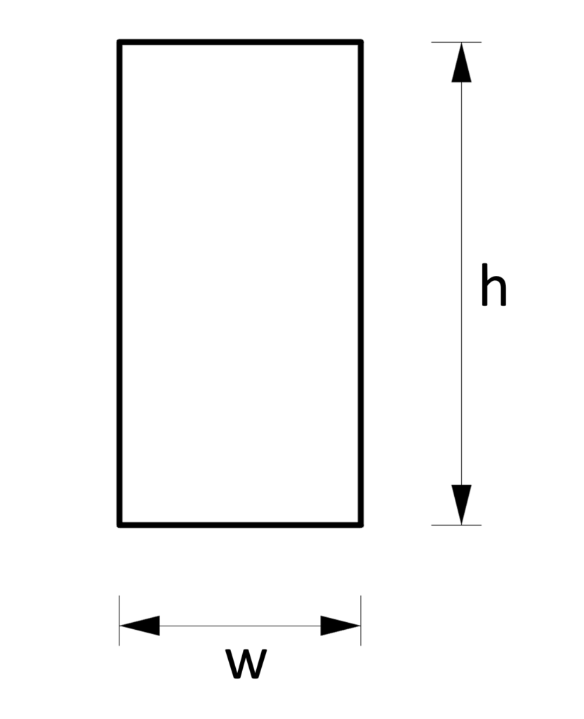
Example calculation
h = 240mm, w = 120mm
Strong axis:
$W_y = \frac{1}{6} \cdot h^2 \cdot w = \frac{1}{6} \cdot (240mm)^2 \cdot 120mm = 1.15 \cdot 10^6 mm^3$
Weak axis:
$W_z = \frac{1}{6} \cdot h \cdot w^3 = \frac{1}{6} \cdot 240mm \cdot (120mm)^2= 5.76 \cdot 10^5 mm^3$
Where is the Section modulus of a rectangular Cross-section used in real projects?
- Structural bending stress calculation of timber beams (here)
- Structural stress calculation of concrete beams
2. Section modulus – I/H shape/section (formula)
Strong Axis
$W_y = \frac{w \cdot h^2}{6} – \frac{(w-t_w) \cdot (h-2\cdot t_f)^3}{6h}$
Weak Axis
$W_z = \frac{w^2 \cdot 2t_f}{6} + \frac{t_w^3 \cdot (h-2t_f)}{6w}$
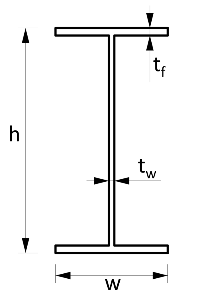
Example calculation
$h$ = 300mm, $w$ = 150mm, $t_f$ = 10mm, $t_w$ = 7mm
Strong axis:
$W_y = \frac{w \cdot h^2}{6} – \frac{(w-t_w) \cdot (h-2\cdot t_f)^3}{6h} = \frac{150mm \cdot (300mm)^2}{6} – \frac{(150mm-7mm) \cdot (300mm-2\cdot 10mm)^3}{6h} = 5.06 \cdot 10^5 mm^3$
Weak axis:
$W_z = \frac{w^2 \cdot 2t_f}{6} + \frac{t_w^3 \cdot (h-2t_f)}{6w} = \frac{(150mm)^2 \cdot 2 \cdot 10mm}{6} + \frac{(7mm)^3 \cdot (300mm-2 \cdot 10mm)}{6\cdot 150mm} = 7.51 \cdot 10^4 mm^3$
Where is the Moment of inertia of a I/H Cross-section used in real projects?
- Structural bending stress calculation of timber I-joists
- Structural bending stress calculation of steel I/H beams and columns
3. Section modulus – Circular shape/section (formula)
Strong Axis
$W_y = \frac{D^3 \cdot \pi}{32}$
Weak Axis
$W_z = \frac{D^3 \cdot \pi}{32}$
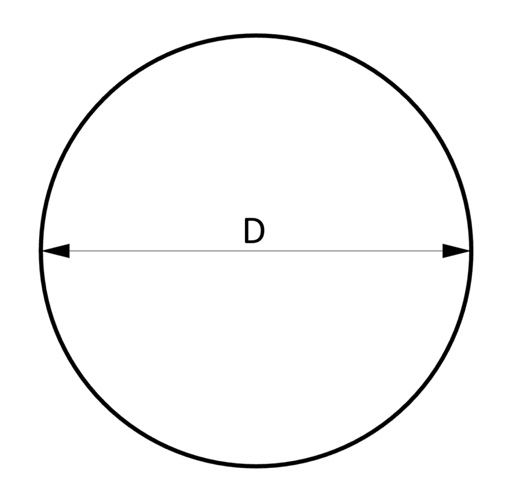
Example calculation
D = 100mm
Strong axis:
$W_y = \frac{D^3 \cdot \pi}{32} = \frac{(100mm)^3 \cdot \pi}{32} = 9.82 \cdot 10^4 mm^3$
Weak axis:
$W_z = \frac{D^3 \cdot \pi}{32} = \frac{(100mm)^3 \cdot \pi}{32} = 9.82 \cdot 10^4 mm^3$
Where is the Section modulus of a circular Cross-section used in real projects?
- Structural steel wind bracing tension rods
- Structural concrete column
4. Section modulus – Hollow circular tube Section (formula)
Strong Axis
$W_y = \frac{(D^4 – d^4) \cdot \pi}{32D}$
Weak Axis
$W_z = \frac{(D^4 – d^4) \cdot \pi}{32D}$
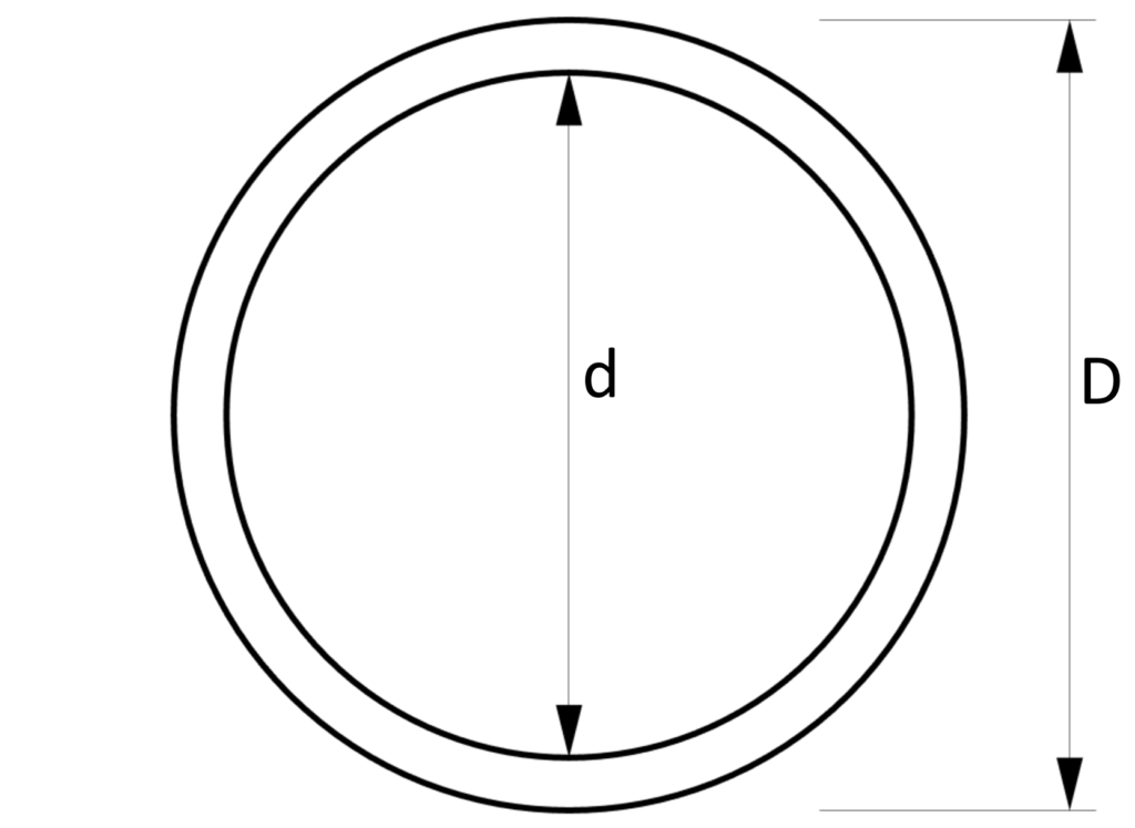
Example calculation
D = 100mm, d = 90mm
Strong axis:
$W_y = \frac{(D^4 – d^4) \cdot \pi}{32D} = \frac{((100mm)^4 – (90mm)^4) \cdot \pi}{32 \cdot 100mm} = 3.376 \cdot 10^4 mm^3$
Weak axis:
$W_z = \frac{(D^4 – d^4) \cdot \pi}{32D} = \frac{((100mm)^4 – (90mm)^4) \cdot \pi}{32 \cdot 100mm} = 3.376 \cdot 10^4 mm^3$
Where is the Section modulus of a circular Cross-section used in real projects?
- Structural steel wind bracing tension rods
- Steel columns
5. Section modulus – Hollow rectangular tube Section (formula)
Strong Axis
$W_y = \frac{W \cdot H^2}{6} – \frac{w \cdot h^3}{6H}$
Weak Axis
$W_z = \frac{W^2 \cdot H}{6} – \frac{w^3 \cdot h}{6W}$
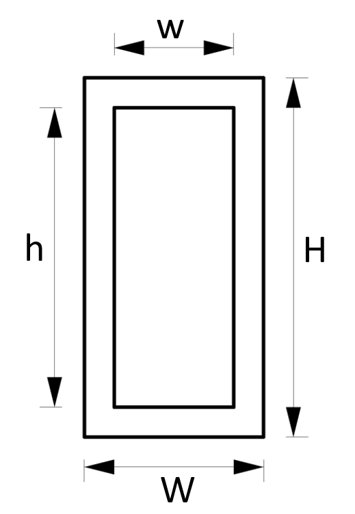
Example calculation
W = 120mm, H = 240mm, w = 100mm, h = 220mm
Strong axis:
$W_y = \frac{W \cdot H^2}{6} – \frac{w \cdot h^3}{6H} = \frac{120mm \cdot (240mm)^2}{6} – \frac{100mm \cdot (220mm)^3}{6\cdot 240mm} = 4.126 \cdot 10^5 mm^3$
Weak axis:
$W_z = \frac{W^2 \cdot H}{6} – \frac{w^3 \cdot h}{6W} = \frac{(120mm)^2 \cdot 240mm}{6} – \frac{(100mm)^3 \cdot 220mm}{6 \cdot 120mm} = 2.704 \cdot 10^5 mm^3$
Where is the Section modulus of a hollow rectangular Cross-section used in real projects?
- Structural Columns
6. Section modulus – U profile/C channel (formula)
Strong Axis
$W_y = \frac{w \cdot h^2}{6} – \frac{(w – t_w) \cdot (h – 2t_f)^3}{6H}$
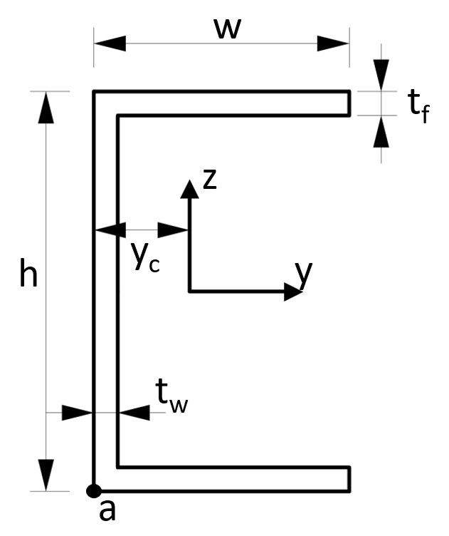
Example calculation
w = 100mm, h = 80mm, $t_f$ = 5mm, $t_w$ = 5mm
Strong axis:
$W_y = \frac{w \cdot h^2}{6} – \frac{(w – t_w) \cdot (h – 2t_f)^3}{6H} = \frac{100mm \cdot (80mm)^2}{6} – \frac{(100mm – 5mm) \cdot (80mm – 2 \cdot 5mm)^3}{6 \cdot 80mm} = 3.878 \cdot 10^4 mm^3$
Where is the Moment of inertia of a U Cross-section used in real projects?
- Bending and buckling analysis of C-profiles, often used in floors (example).
7. Section modulus – T section/profile (formula)
Weak Axis
$W_z = \frac{t_f \cdot w^2}{6} + \frac{h \cdot t_w^3}{6\cdot w}$
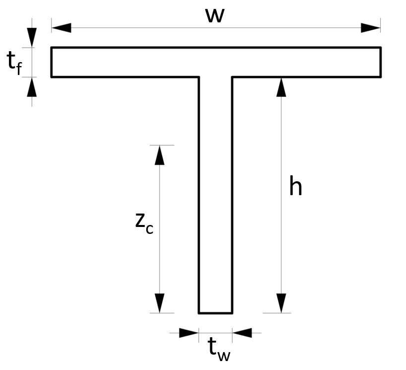
Example calculation
w = 100mm, h = 100mm, $t_f$ = 5mm, $t_w$ = 5mm
Weak axis:
$W_z = \frac{t_f \cdot w^2}{6} + \frac{h \cdot t_w^3}{6 \cdot w}$
$W_z = \frac{5mm \cdot (100mm)^2}{6} + \frac{100mm \cdot (5mm)^3}{6 \cdot 100mm}$
$W_z = 8.354 \cdot 10^3 mm^3$
8. Unsymmetrical I-Section
Weak axis
$W_z =\frac{I_z}{w_t/2}$
Strong axis top fibre
$W_y= \frac{I_y}{z_s}$
Strong axis bottom fibre
$W_y= \frac{I_y}{h – z_s}$
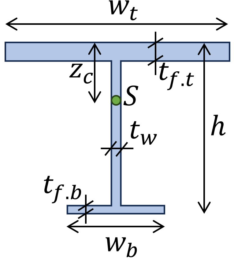
Distance to centroid S:
$z_c = (\frac{1}{w_b \cdot t_{f.t}+w_b \cdot t_{f.b}+(h-t_{f.t}-t_{f.b}) \cdot t_w}) \cdot (w_t \cdot t_{f.t} \cdot \frac{t_{f.t}}{2}+(h-t_{f.t}-t_{f.b}) \cdot t_w \cdot(t_{f.t}+\frac{(h-t_{f.t}-t_{f.b}}{2})$
$+w_b \cdot t_{f.b} \cdot(h-\frac{t_{f.b}}{2}))$
Click here to see the moment of inertia formulas.
Example Calculation
$w_t = 200mm$, $w_b = 100mm$, $h = 200mm$, $t_{f.t} = 20mm$, $t_{f.b} = 10mm$, $t_w = 10mm$
Weak axis:
$I_z = \frac{20mm \cdot (200mm)^3}{12} + \frac{(200mm-20mm-10mm)\cdot (10mm)^3}{12} +\frac{10mm \cdot (100mm)^3}{12} = 1.418 \cdot 10^7 mm^4$
$W_z = \frac{I_z}{w_t/2} = \frac{1.418 \cdot 10^7 mm^4}{100mm} = 1.418 \cdot 10^5 mm^3$
Distance to centroid S:
$z_c = (\frac{1}{200mm \cdot 20mm+100mm \cdot 10mm+(200mm-20mm-10mm) \cdot 10mm}) \cdot$
$(200mm \cdot 20mm \cdot \frac{20mm}{2}+(200mm-20mm-10mm) \cdot 10mm \cdot(20mm+\frac{200mm-20mm-10mm}{2})$
$+100mm \cdot 10mm \cdot(200mm-\frac{10mm}{2})) = 61.72mm$
Strong axis:
$I_y=\frac{200mm \cdot (20mm)^3}{12}+200mm \cdot 20mm \cdot(61.72mm-\frac{20mm}{2})^2+\frac{10mm \cdot(200mm-20mm-10mm)^3}{12}$
$+10mm \cdot(200mm-20mm-10mm) \cdot(61.72mm-(20mm+\frac{(200mm-20mm-10mm)}{2}))^2$
$+\frac{100mm \cdot (10mm)^3}{12}+100mm \cdot 10mm \cdot(61.72mm-200mm-\frac{10mm}{2})^2 = 3.865 \cdot 10^7 mm^4$
Bottom fibre:
$W_y = \frac{I_y}{h – z_c} = \frac{3.865 \cdot 10^7 mm^4}{200mm – 61.7mm} = 2.795 \cdot 10^5 mm^3$
Conclusion
If you are new to structural design, then check out our design tutorials where you can learn how to use the moment of inertia and section modulus to design structural elements such as
Do you miss any section modulus formulas for any shape or Cross-section that we forgot in this article? Let us know in the comments. ✍️✍️
Section Modulus FAQ
The Section modulus S is calculated by dividing the Moment of Inertia I by the distance z from the Cross-section centre to the edge.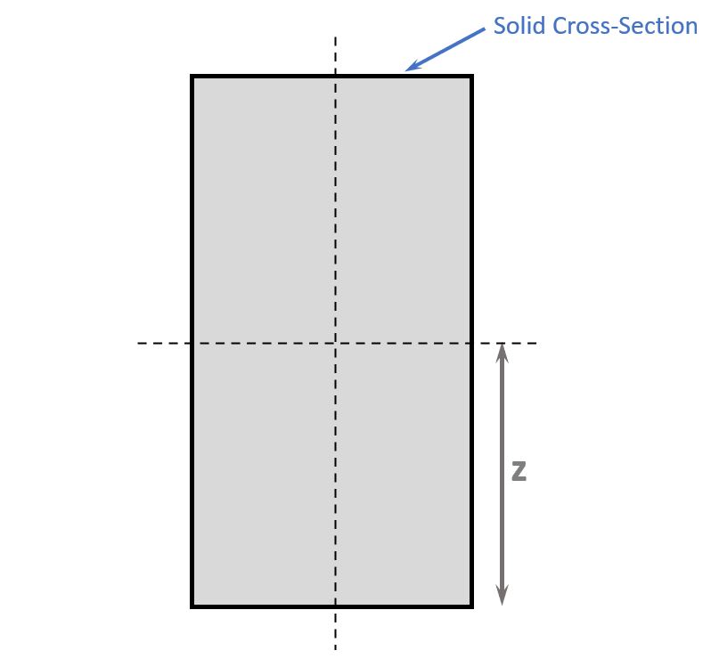
The unit of the section modulus is mm^3 [milimeter^3].
Yes, the section modulus can also be called first moment of area.
![Timber Truss Roof Design [A Structural Guide]](https://www.structuralbasics.com/wp-content/uploads/2022/04/Timber-Truss-Roof-Design-768x439.jpg)
![What Is A Roof Joist? [2026]](https://www.structuralbasics.com/wp-content/uploads/2023/04/What-is-a-roof-joist-768x439.jpg)
Great article.
Thanks!