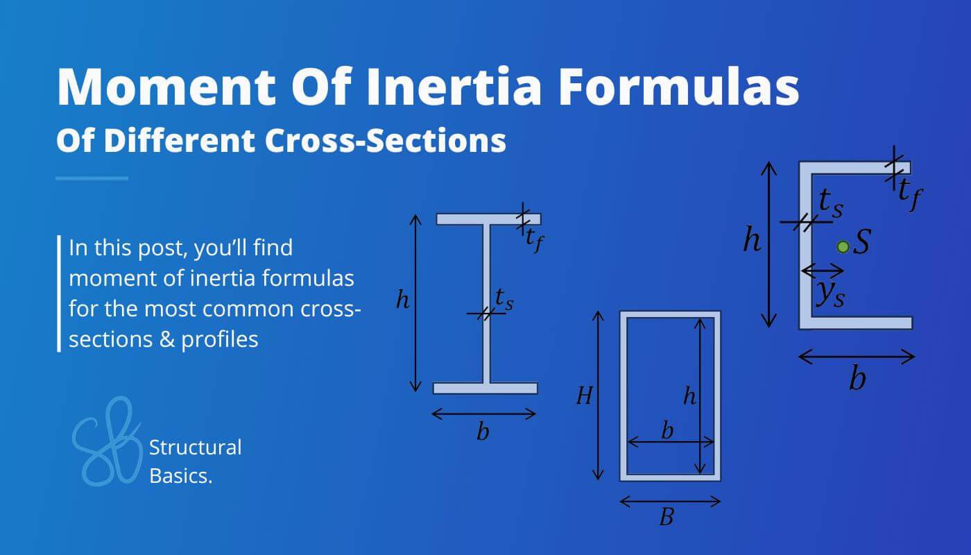
Moment Of Inertia Formulas For Different Shapes {2026}
Calculating moment of inertias for different shapes and Cross-sections is probably the one thing in structural engineering that we use throughout our studies and also careers later on.
While it’s very important to know how to derive and calculate the Moment of inertias, the further we get in our studies, the more we can use formulas.
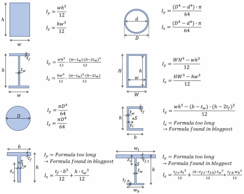
In this post we’ll show, the most important and easiest formulas for Rectangular, I/H, Circular and hollow circular section but also formulas which involve more steps for L-, T- and U- Shapes.
Before getting into it. If you want to have all moment of inertia formulas as a PDF then download our free Structural Design Cheatsheet.
But now, let’s get started. 🚀🚀
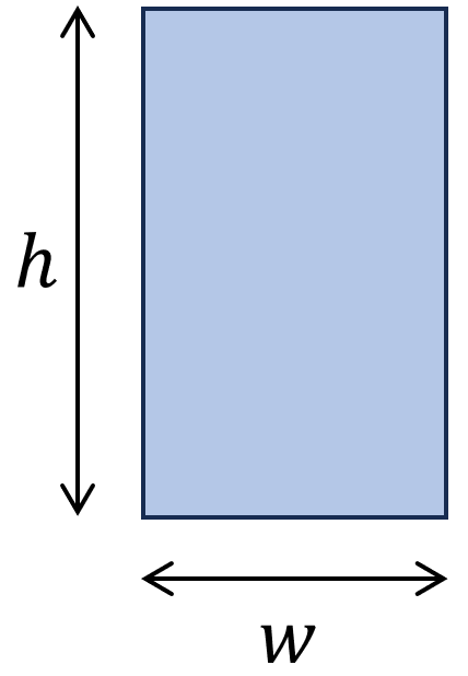
1. Moment of inertia – Rectangular shape/section (formula)
Strong Axis
$I_y = \frac{1}{12} \cdot h^3 \cdot w$
Weak Axis
$I_z = \frac{1}{12} \cdot h \cdot w^3$
Example calculation
h = 240 mm, w = 120 mm
Strong axis:
$$I_y = \frac{1}{12} \cdot h^3 \cdot w = \frac{1}{12} \cdot (240mm)^3 \cdot 120mm = 1.3824 \cdot 10^8 mm^4$$
Weak axis:
$$I_z = \frac{1}{12} \cdot h \cdot w^3 = \frac{1}{12} \cdot 240mm \cdot (120mm)^3= 3.456 \cdot 10^7 mm^4$$
Where is the Moment of inertia of a rectangular cross-section used in real projects?
- Structural bending stress calculation of timber beams (here)
- Structural stress calculation of (steel) plates
- Structural stress calculation of concrete beams
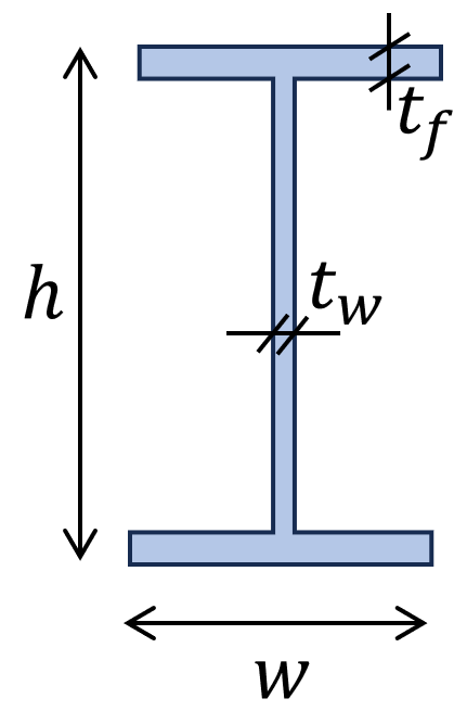
2. Moment of inertia – I/H shape/section (formula)
Strong Axis
$I_y = \frac{w \cdot h^3}{12} – \frac{(w-t_w) \cdot (h-2\cdot t_f)^3}{12}$
Weak Axis
$I_z = \frac{(h-2 \cdot t_f) \cdot t_w^3}{12} + \frac{2 \cdot t_f \cdot w^3}{12}$
Example calculation
$h$ = 300mm, $w$ = 150mm, $t_f$ = 10mm, $t_w$ = 7mm
Strong axis:
$$I_y = \frac{w \cdot h^3}{12} – \frac{(w-t_w) \cdot (h-2\cdot t_f)^3}{12}$$
$$I_y = \frac{150mm \cdot (300mm)^3}{12} – \frac{(150mm-7mm) \cdot (300mm-2\cdot 10mm)^3}{12} = 7.59 \cdot 10^7 mm^4$$
Weak axis:
$$I_z = \frac{(h-2\cdot t_f) \cdot t_w^3}{12} + \frac{2\cdot t_f \cdot w^3}{12}$$
$$I_z = \frac{(300mm-2\cdot 10mm) \cdot (7mm)^3}{12} + \frac{2\cdot 10mm \cdot (7mm)^3}{12} = 5.63 \cdot 10^6 mm^4$$
Where is the Moment of inertia of a I/H cross-section used in real projects?
- Structural bending stress calculation of timber I-joists
- Structural bending stress calculation of steel I/H beams and columns
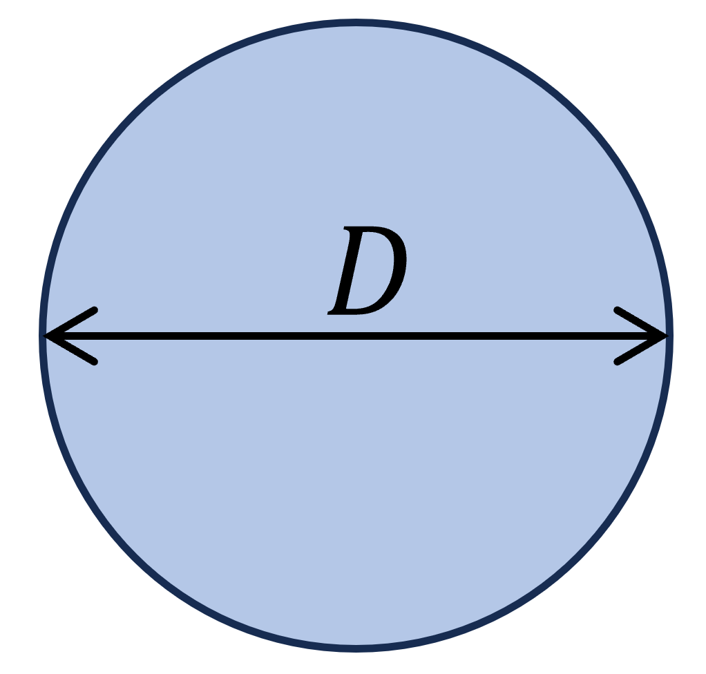
3. Moment of inertia – Circular shape/section (formula)
Strong Axis
$I_y = \frac{D^4 \cdot \pi}{64}$
Weak Axis
$I_z = \frac{D^4 \cdot \pi}{64}$
Example calculation
D = 100mm
Strong axis:
$$I_y = \frac{D^4 \cdot \pi}{64} = \frac{(100mm)^4 \cdot \pi}{64} = 4.91 \cdot 10^6 mm^4$$
Weak axis:
$$I_z = \frac{D^4 \cdot \pi}{64} = \frac{(100mm)^4 \cdot \pi}{64} = 4.91 \cdot 10^6 mm^4$$
Where is the Moment of inertia of a circular cross-section used in real projects?
- Structural steel wind bracing tension rods
- Structural concrete column
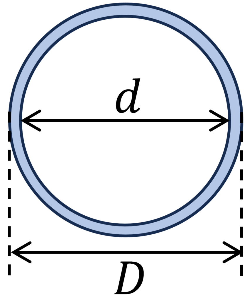
4. Moment of inertia – Hollow circular tube Section (formula)
Strong Axis
$I_y = \frac{(D^4-d^4) \cdot \pi}{64}$
Weak Axis
$I_z = \frac{(D^4-d^4) \cdot \pi}{64}$
Example calculation
D = 100mm, d = 90mm
Strong axis:
$$I_y = \frac{(D^4 – d^4) \cdot \pi}{64} = \frac{((100mm)^4 – (90mm)^4) \cdot \pi}{64} = 1.688 \cdot 10^6 mm^4$$
Weak axis:
$$I_z = \frac{(D^4 – d^4) \cdot \pi}{64} = \frac{((100mm)^4 – (90mm)^4) \cdot \pi}{64} = 1.688 \cdot 10^6 mm^4$$
Where is the Moment of inertia of a circular cross-section used in real projects?
- Structural steel wind bracing tension rods
- Steel columns
5. Moment of inertia – Hollow rectangular tube Section (formula)
Strong Axis
$I_y = \frac{W \cdot H^3 -w \cdot h^3}{12}$
Weak Axis
$I_z = \frac{W^3 \cdot H -w^3 \cdot h}{12}$
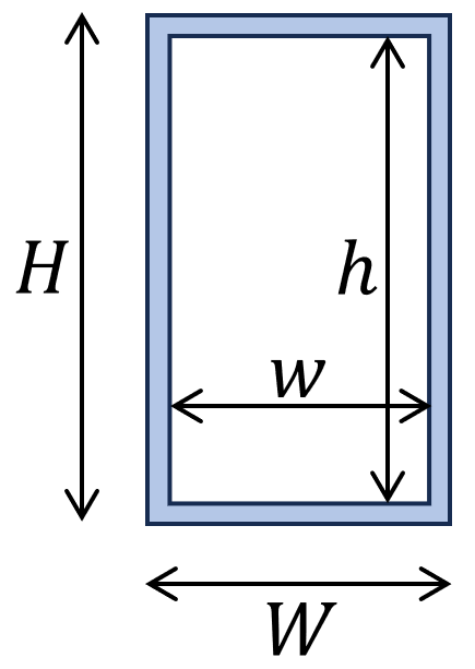
Example calculation
W = 120mm, H = 240mm, w = 100mm, h = 220mm
Strong axis:
$$I_y = \frac{W \cdot H^3 – w \cdot h^3}{12} = \frac{120mm \cdot (240mm)^3 – 100mm \cdot (220mm)^3}{12}= 4.95 \cdot 10^7 mm^4$$
Weak axis:
$$I_z = \frac{W^3 \cdot H – w^3 \cdot h}{12} = \frac{(120mm)^3 \cdot 240mm – (100mm)^3 \cdot 220mm}{12} = 1.62 \cdot 10^7 mm^4$$
Where is the Moment of inertia of a circular cross-section used in real projects?
- Columns
6. Moment of inertia – U profile (formula)
Strong Axis
$I_y = \frac{w \cdot h^3 -(w-t_w)\cdot (h-2t_f)^3}{12}$
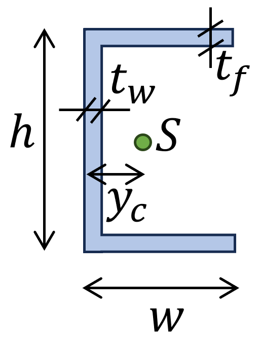
Distance point a to centroid:
$$y_{c} = \frac{1}{(h-2t_f) \cdot t_w + 2 \cdot w \cdot t_f} \cdot ((h-2t_f) \cdot t_w \cdot \frac{t_w}{2} + 2 \cdot w \cdot t_f \cdot \frac{w}{2})$$
Moment of Inertia – weak axis:
$$I_z = \frac{(h-2 \cdot t_f) \cdot t_w^3}{12} + (h-2 \cdot t_f) \cdot t_w \cdot (y_c – \frac{t_w}{2})^2 + \frac{2 \cdot t_f \cdot w^3}{12} + 2 \cdot w \cdot t_f \cdot (\frac{w}{2} – y_c)^2$$
Example calculation
w = 100mm, h = 80mm, $t_f$ = 5mm, $t_w$ = 5mm
Strong axis:
$I_y = \frac{w \cdot h^3 – (w – t_w) \cdot (h – 2t_f)^3}{12} = \frac{100mm \cdot (80mm)^3 – (100mm – 5mm) \cdot (80mm – 2\cdot 5mm)^3}{12}= 1.55 \cdot 10^6 mm^4$
Distance point a to centroid:
$y_{c} = \frac{1}{(h-2t_f) \cdot t_w + 2 \cdot w \cdot t_f} \cdot ((h-2t_f) \cdot t_w \cdot \frac{t_w}{2} + 2 \cdot w \cdot t_f \cdot \frac{w}{2})$
$y_{c} = \frac{1}{(80mm-2\cdot 5mm) \cdot 5mm + 2 \cdot 100mm \cdot 5mm} \cdot ((80mm-2 \cdot 5mm) \cdot 5mm \cdot \frac{5mm}{2}$ $
+ 2 \cdot 100mm \cdot 5mm \cdot \frac{100mm}{2})$
$y_c = 37.69mm$
Weak axis:
$I_z = \frac{(h-2 \cdot t_f) \cdot t_w^3}{12} + (h-2 \cdot t_f) \cdot t_w \cdot (y_c – \frac{t_w}{2})^2 + \frac{2 \cdot t_f \cdot w^3}{12} + 2 \cdot w \cdot t_f \cdot (\frac{w}{2} – y_c)^2$
$I_z = \frac{(80mm-2 \cdot 5mm) \cdot (5mm)^3}{12} + (80mm-2 \cdot 5mm) \cdot 5mm \cdot (37.69mm – \frac{5mm}{2})^2$
$ + \frac{2 \cdot 5mm \cdot (100mm)^3}{12} + 2 \cdot 100mm \cdot 5mm \cdot (\frac{100mm}{2} – 37.69mm)^2$
$I_z = 1.42 \cdot 10^6 mm^4$
Where is the Moment of inertia of a U cross-section used in real projects?
- Wind bracing of steel or timber structures
7. Moment of inertia – T profile (formula)
Weak Axis
$I_z = \frac{t_f \cdot w^3}{12} + \frac{h \cdot t_w^3}{12}$
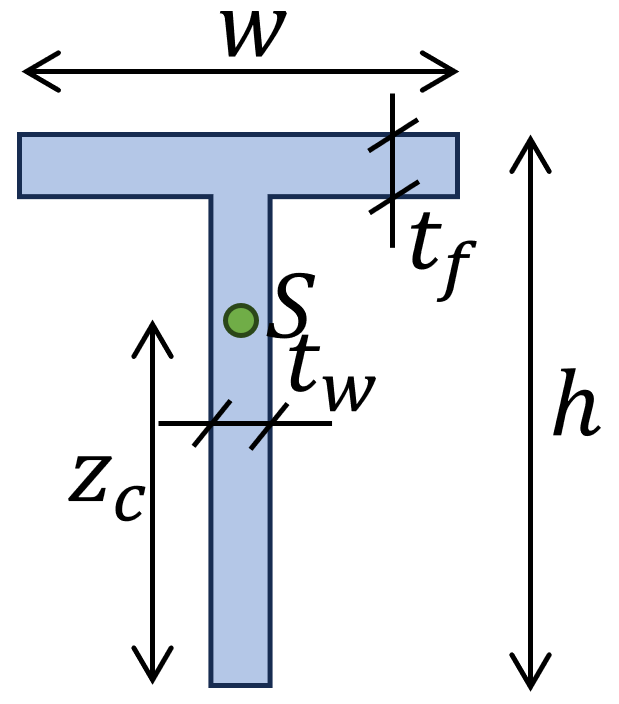
Distance point $z_c$ to centroid:
$$z_{c} = \frac{1}{h \cdot t_w + w \cdot t_f} \cdot (h \cdot t_w \cdot \frac{h}{2} + w \cdot t_f \cdot (h + \frac{t_f}{2})$$
Moment of inertia – Weak axis:
$$I_y = \frac{h^3 \cdot t_w}{12} + h \cdot t_w \cdot (\frac{h}{2} – z_c)^2 + \frac{t_f \cdot w^3}{12} + w \cdot t_f \cdot (h + \frac{t_f}{2} – z_c)^2$$
Example calculation
w = 100mm, h = 100mm, $t_f$ = 5mm, $t_w$ = 5mm
Distance $z_c$ to centroid:
$$z_{c} = \frac{1}{h \cdot t_w + w \cdot t_f} \cdot (h \cdot t_w \cdot \frac{h}{2} + w \cdot t_f \cdot (h + \frac{t_f}{2})$$
$$z_{c} = \frac{1}{100mm \cdot 5mm + 100mm \cdot 5mm} \cdot (100mm \cdot 5mm \cdot \frac{100mm}{2} + 100mm \cdot 5mm \cdot (100mm + \frac{5mm}{2})$$
$$z_c = 76.25mm$$
Strong axis:
$$I_y = \frac{h^3 \cdot t_w}{12} + h \cdot t_w \cdot (\frac{h}{2} – z_c)^2 + \frac{t_f \cdot w^3}{12} + w \cdot t_f \cdot (h + \frac{t_f}{2} – z_c)^2 $$
$$I_y = \frac{(100mm)^3 \cdot 5mm}{12} + 100mm \cdot 5mm \cdot (\frac{100mm}{2} – 76.25mm)^2 + \frac{5mm \cdot (100mm)^3}{12}$$
$$ + 100mm \cdot 5mm \cdot (100mm + \frac{5mm}{2} – 76.25mm)^2 $$
$$I_y = 1.107 \cdot 10^6 mm^4$$
Weak axis:
$$I_z = \frac{t_f \cdot w^3}{12} + \frac{h \cdot t_w^3}{12}$$
$$I_z = \frac{5mm \cdot (100mm)^3}{12} + \frac{100mm \cdot (5mm)^3}{12}$$
$$I_z = 4.177 \cdot 10^5 mm^4$$
8. Moment of inertia – Unsymmetrical I/H profile (formula)
Weak Axis
$I_z = \frac{t_{f.t} \cdot w_{t}^3}{12} + \frac{(h-t_{f.t}-t_{f.b})\cdot t_w^3}{12} +\frac{t_{f.b} \cdot w_{b}^3}{12}$
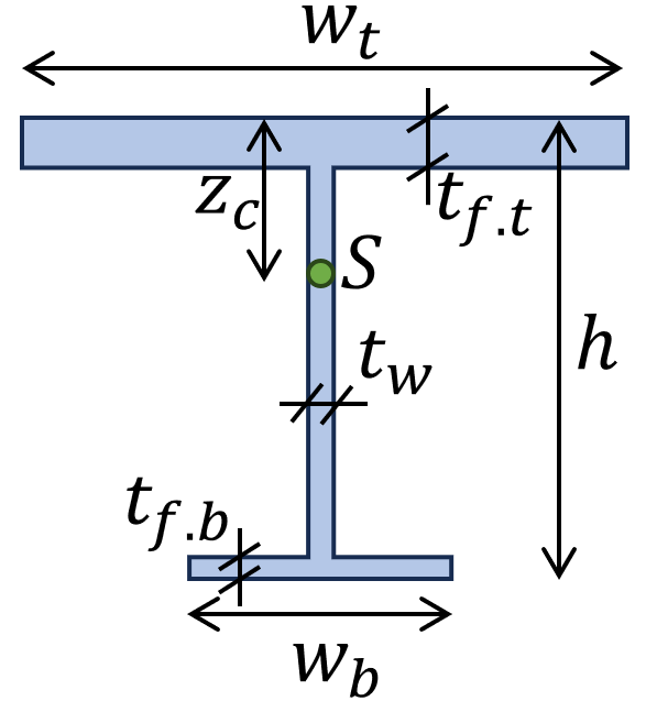
Distance point $z_c$ to centroid:
$z_c=(\frac{1}{w_t \cdot t_{f.t}+w_b \cdot t_{f.b}+(h-t_{f.t}-t_{f.b}) \cdot t_w}) \cdot (w_t \cdot t_{f.t} \cdot \frac{t_{f.t}}{2}+(h-t_{f.t}-t_{f.b}) \cdot t_w \cdot(t_{f.t}+\frac{(h-t_{f.t}-t_{f.b}}{2})$
$+w_b \cdot t_{f.b} \cdot(h-\frac{t_{f.b}}{2}))$
Moment of inertia – Weak axis:
$I_y=\frac{w_t \cdot t_{f.t}^3}{12}+w_t \cdot t_{f.t} \cdot(z_c-\frac{t_{f.t}}{2})^2+\frac{t_w \cdot(h-t_{f.t}-t_{f.b})^3}{12}$
$+t_w \cdot(h-t_{f.t}-t_{f.b}) \cdot(z_c-(t_{f.t}+\frac{(h-t_{f.t}-t_{f.b})}{2}))^2+\frac{w_b \cdot t_{f.b}^3}{12}+w_b \cdot t_{f.b} \cdot(z_c-h-\frac{t_{f.b}}{2})^2$
Example calculation
$w_t = 200mm$, $w_b = 100mm$, $h = 200mm$, $t_{f.t} = 20mm$, $t_{f.b} = 10mm$, $t_w = 10mm$
Distance $z_c$ to centroid:
$z_c=(\frac{1}{200mm \cdot 20mm+100mm \cdot 10mm+(200mm-20mm-10mm) \cdot 10mm}) \cdot$
$(200mm \cdot 20mm \cdot \frac{20mm}{2}+(200mm-20mm-10mm) \cdot 10mm \cdot(20mm+\frac{200mm-20mm-10mm}{2})$
$+100mm \cdot 10mm \cdot(200mm-\frac{10mm}{2})) = 61.72mm$
Strong axis:
$I_y=\frac{200mm \cdot (20mm)^3}{12}+200mm \cdot 20mm \cdot(61.72mm-\frac{20mm}{2})^2+\frac{10mm \cdot(200mm-20mm-10mm)^3}{12}$
$+10mm \cdot(200mm-20mm-10mm) \cdot(61.72mm-(20mm+\frac{(200mm-20mm-10mm)}{2}))^2$
$+\frac{100mm \cdot (10mm)^3}{12}+100mm \cdot 10mm \cdot(61.72mm-200mm-\frac{10mm}{2})^2 = 3.865 \cdot 10^7 mm^4$
Weak axis:
$I_z = \frac{20mm \cdot (200mm)^3}{12} + \frac{(200mm-20mm-10mm)\cdot (10mm)^3}{12} +\frac{10mm \cdot (100mm)^3}{12} = 1.418 \cdot 10^7 mm^4$
Units
The unit of the moment of inertia is the fourth power of a length unit [length4]. If you would like to use $mm$ in your calculation, then the unit of the moment of inertia is mm4.
In case you use m [meter], then the unit is m4.
Conclusion
The moment of inertia is an important parameter in structural design. Therefore, it’s recommendable to know how to calculate it for different cross-sections.
In the following blog posts, we show step-by-step, how to calculate moment of inertias.
If you are new to structural design, then check out our design tutorials where you can learn how to use the moment of inertia to design structural elements such as
If you don’t want to miss any new structural design tutorials, then subscribe to our free weekly newsletter.
Or subscribe to my YouTube channel for regular updates.
Let’s design better structures together,
Laurin.

Laurin Ernst