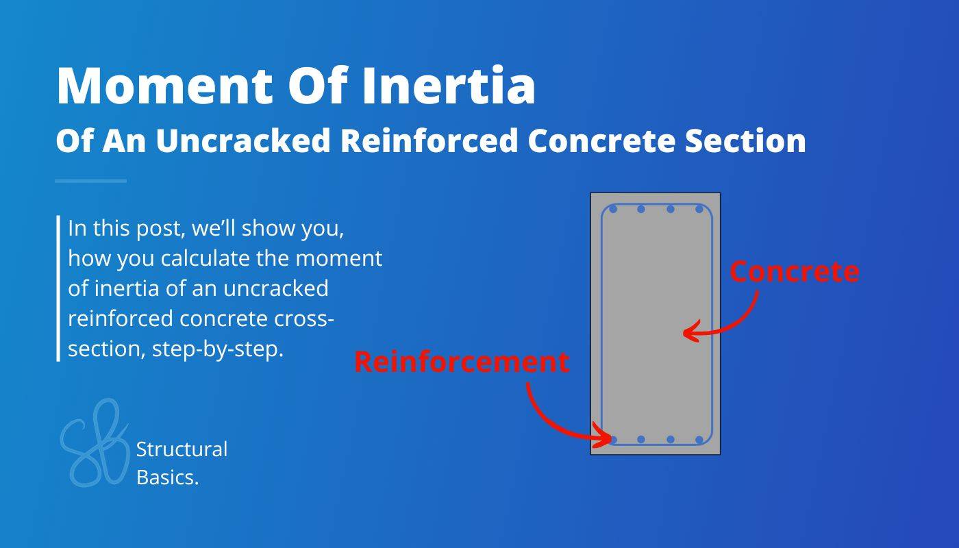
Moment Of Inertia Of An Uncracked Reinforced Concrete Section
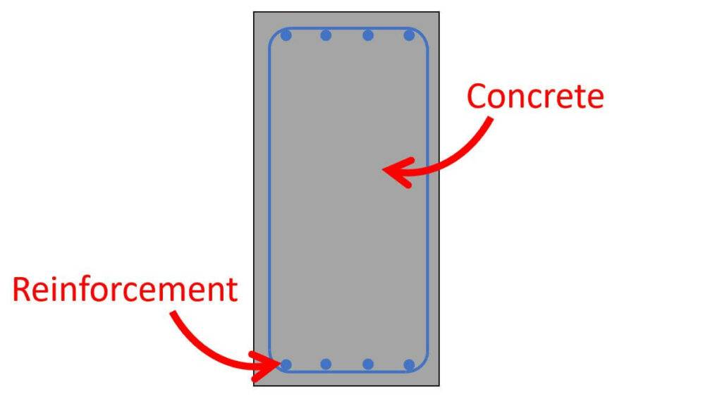
Reinforced concrete sections are one of the most used cross-sections in structural engineering. You need the moment of inertia of that when you design a reinforced concrete beam or floor.
The process you find in this post can also be applied to other composite sections like timber and concrete floors or a section with steel beams and a concrete deck (used in bridges).
In this guide, I’ll show you how you calculate the moment of inertia of uncracked reinforced concrete sections.
Reinforced concrete sections are mostly cracked. In that case, the moment of inertia is a lot smaller. Check out this guide to learn how to calculate it for cracked sections.
Alright, let’s get started. 🚀🚀
Process Of Calculating The Moment Of Inertia Of An Uncracked Reinforced Concrete Section
Here are the steps, we need to follow to calculate the moment of inertia of a rectangular reinforced concrete section (we’ll calculate and define all parameters in the last section):
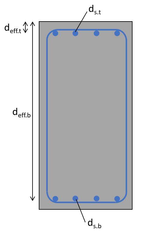
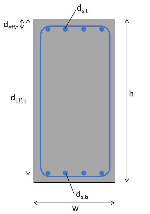
- Define properties of the reinforced concrete section (Longitudinal reinforcement at bottom ds.b and top ds.t, effective height of the reinforcement deff, E-moduli of steel Es and concrete Ec.eff, cross-sectional dimensions h and b, etc.)
- Ratio between moduli:
$$\alpha = \frac{E_s}{E_{c.eff}}$$ - Cross-sectional area (composite rectangular section)
$$A_a = w \cdot h + \alpha \cdot (A_{s.t} + A_{s.b})$$ - Moment of inertia (composite section)
$$I_a = \frac{w \cdot h^3}{12} + \alpha \cdot A_{s.t} \cdot (h/2 – d_{s.t})^2 + \alpha \cdot A_{s.b} \cdot (h/2 – d_{s.b})^2$$
In the last section of this post, we’ll run through an example calculation of a reinforced concrete cross-section. 👇👇
Why Are The Moment Of Inertia’s Of Composite Sections Different?
Because a composite element consists of 2 materials which most likely have different stiffness and strength parameters.
Imagine this: Take a few pieces of paper and bend it. It’s pretty easy, right? This is because the bending stiffness of the paper is very low (E-modulus * moment of inertia).
Next, let’s add a pen in between the paper. Now it’s very difficult to bend it, right?
It’s because the pen has a much higher bending stiffness. This is an extreme example because the stiffnesses of paper and pen are so far apart from each other, but it’s the same principle for reinforced concrete sections (if we leave out cracking for a moment). Concrete has a lower E-modulus as steel (reinforcement), which means that a concrete beam without steel bends more easily.
To account for this increased stiffness with reinforcement in the design calculations like bending and deflection verifications, we calculate the moment of inertia of the composite section, taking into account the different E-moduli.
Alright, let’s have a look at how we calculate the moment of inertia. 👇👇
Example Calculation Of The Moment Of Inertia
Now, let’s apply this to an example with the following parameters.
Geometrical parameters
| Cross-sectional height | $h = 400 mm$ |
| Cross-sectional width | $w = 300 mm$ |
| Concrete cover | $c = 25 mm$ |
| Stirrup diameter | $d_{s.s} = 8 mm$ |
| Top reinforcement – diameter | $d_{s.t} = 16 mm$ |
| Top reinforcement – number of bars | $n_{s.t} = 4$ |
| Top reinforcement – effective height | $d_{eff.t} = c + d_{s.s} + d_{s.t}/2 = 41 mm$ |
| Top reinforcement – cross-sectional area | $A_{s.t} = n_{s.t} \cdot (d_{s.t}/2)^2 \cdot \pi = 804.2 mm^2$ |
| Bottom reinforcement – diameter | $d_{s.b} = 16 mm$ |
| Bottom reinforcement – number of bars | $n_{s.b} = 4$ |
| Bottom reinforcement – effective height | $d_{eff.b} = h – c – d_{s.s} – d_{s.b}/2 = 41 mm$ |
| Bottom reinforcement – cross-sectional area | $A_{s.b} = n_{s.b} \cdot (d_{s.b}/2)^2 \cdot \pi = 804.2 mm^2$ |
Material parameters
| E-modulus of reinforcement | $E_s = 200 GPa$ |
| E-modulus of concrete (C25) EN 1992-1-1 Table 3.1 | $E_{cm} = 31 GPa$ |
| Creep factor (assumption*) | $\varphi_{28} = 2.0$ |
| Effective e-modulus of concrete | $E_{c.eff} = \frac{E_{cm}}{1 + \varphi_{28}} = 10.3 GPa$ |
1. First, we’ll calculate the ratio between the reinforcement and concrete moduli:
$$\alpha = \frac{E_s}{E_{c.eff}} = 19.4$$
There you can see that the reinforcement is 19.4 times “stiffer” if you use the same amount of material.
2. Next, we’ll calculate the cross-sectional area of the composite section, taking into account that the reinforcement is stiffer:
$$A_a = w \cdot h + \alpha \cdot (A_{s.t} + A_{s.b}) = 1.51 \cdot 10^5 mm^2$$
3. Then, as the last step, the moment of inertia of the composite section:
$$I_a = \frac{w \cdot h^3}{12} + \alpha \cdot A_{s.t} \cdot (h/2 – d_{s.t})^2 + \alpha \cdot A_{s.b} \cdot (h/2 – d_{s.b})^2 = 2.654 \cdot 10^9 mm^4$$
Conclusion
The same calculation principle can be applied to other composite cross-sections, like timber and concrete or steel and concrete sections. You calculate the ratio between the 2 moduli and apply this ratio to the moment of inertia of that material.
In most cases, concrete cracks. This happens when the tensile strength of the concrete is reached. Once concrete cracks, it loses a lot of its stiffness and all the tension forces of a cross-section are taken by the reinforcement. This moves the neutral axis of the cross-section and therefore also the moment of inertia.
Cracked cross-sections lead to much bigger deflections due to its reduced stiffness.
Check out this guide to learn how to calculate the moment of inertia of cracked sections.

![How to Calculate The Cross Sectional Area? [A Beginner’s Guide]](https://www.structuralbasics.com/wp-content/uploads/2023/01/how-to-calculate-the-cross-sectional-area-768x439.jpg)
![Centroid of I Beam: Calculation Example [2026]](https://www.structuralbasics.com/wp-content/uploads/2023/02/Centroid-of-I-Beam-768x439.jpg)
![9+ Polar Moment Of Inertia Formulas [2026]](https://www.structuralbasics.com/wp-content/uploads/2023/09/2nd-polar-moment-of-inertia-formulas-768x439.jpg)