Flat Slab Design {2026 Structural Guide}
A flat slab is a structural floor commonly used in buildings to withstand vertical loads and distribute them to columns.
In this guide, we’ll show step-by-step, how you design and verify flat slabs for bending, punching shear, crack and deflections.
Let’s get started. 🚀🚀
What Is A Flat Slab?
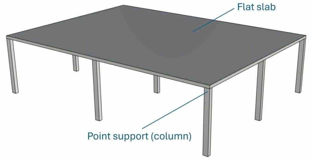
A flat slab is a reinforced concrete slab which is supported by point support such as columns instead of line supports like beams or walls. This design comes with a couple of benefits such as
- increased floor to floor height
- faster construction because of the elimination of one element (beams)
- less intersections between the structure and installations such as pipes and ducts
The design and verification of punching shear is covered by EN 1992-1-1 6.4.
Process of Flat Slab Design
Before we dive into the nerdy calculations, it’s good to get an overview of the steps that need to be taken to design and verify a reinforced concrete flat slab. 👇👇
- Define geometry properties of the slab and column
- Calculate characteristic area loads that act on the slab
- Load combinations to find the design loads
- Define material properties of the slab
- Bending moments
- ULS bending verification and design of longitudinal reinforcement
- ULS punching shear verification
- SLS crack width verification
- SLS deflection verification
We are showing all calculation steps for the following simplified example where columns and walls support a reinforced concrete slab.
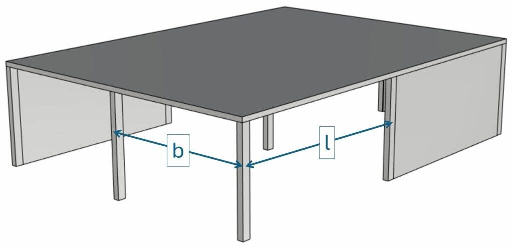
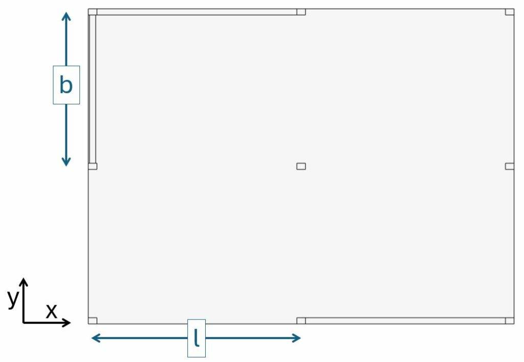
1. Geometry Properties Of The Slab
The slab and the column have the following geometric properties:
| Slab/Plate thickness | $t_{p} = 0.25 m$ |
| Column cross-section width | $w = 0.2 m$ |
| Column cross-section height | $h = 0.3 m$ |
| Column spacing (see image above) | $l = 7.5 m$ |
| Column spacing (see image above) | $b = 6.0 m$ |
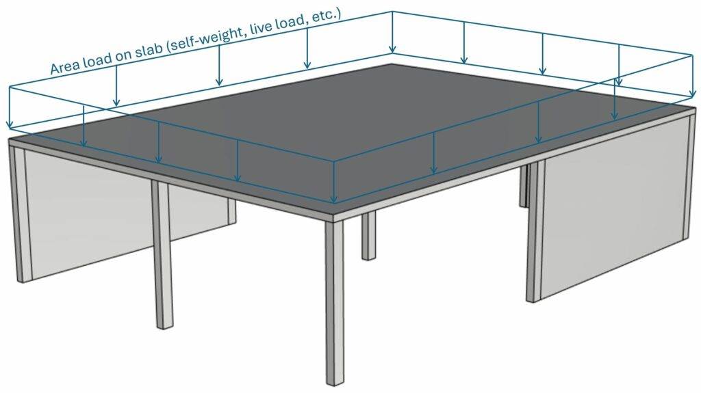
2. Characteristic Loads
In this tutorial we’ll simplify the calculation of the loads. We assume that we design a reinforced concrete slab with thickness tp = 0.25m. The slab is exposed to the following area loads: ⬇️⬇️
| Characteristic dead load of the rc slab | $g_{k.s} = 25 kN/m^3 \cdot t_p = 6.25 kN/m^2$ |
| Characteristic dead load of the flooring | $g_{k.f} = 1.6 kN/m^2$ |
| Live load (value for offices in Denmark) | $q_k = 2.5 kN/m^2$ |
3. Load Combinations
Load combinations combine several load cases and multiply the characteristic loads with safety factors.
Luckily, we have already written an extensive article about what load combinations are and how we use them.
In case you need to brush up on it or want to check how we derived the safety factors, you can read the blog post here.
The bending moments of the slab are calculated for a continuous beam. We’ll later find the maximum bending moments in the span and at the center support. But because different load distributions lead to different moments, we’ll define the design loads for:
- dead load + live load
- dead load
- live load
ULS load combinations
| LC1 – dead and live load | $1.35 \cdot (g_{k.s} + g_{k.f}) + 1.5 \cdot q_k $ | $14.35 kN/m^2$ | |
| LC1 – dead load | $1.35 \cdot (g_{k.s} + g_{k.f})$ | $10.6 kN/m^2$ | |
| LC1 – live load | $1.5 \cdot q_k $ | $3.75 kN/m^2$ |
Now, in our case, we only use one load combination, because we simplify this tutorial. Usually, you have to consider multiple load combinations. However, from experience, we can say that for an indoor office slab, this load combination is governing in most situations.
With the design loads, we can now calculate the bending moments in the slab. 👇👇
💡💡 Info:
If you calculate the bending moments force of the slab with a FE model, you won’t get the exact same result. Beams and slabs don’t have exactly the same behaviour, and we use beam formulas to calculate the bending moments. The stiffness of the slab and columns in the FE model also have an influence of where the load travels.
4. Concrete and Reinforcement Properties
| Concrete compression | $f_{c.k} = 30 MPa$ |
| Partial factor in-situ concrete (Denmark) | $\gamma_c = 1.45$ |
| Design concrete compression strength | $f_{c.d} = 20.7 MPa$ |
| Reinforcement yield strength | $f_{y.k} = 500 MPa$ |
| Partial factor reinforcement (Denmark) | $\gamma_s = 1.2$ |
| Design yield strength | $f_{y.d} = \frac{f_{y.k}}{\gamma_s} = 416.7 MPa$ |
| Rebar cover | $c = 30 mm$ |
| E-modulus of concrete (C30) | $E_{cm} = 32837 MPa$ |
We’ll also assume the longitudinal reinforcement of the slab. Keep in mind that we didn’t calculate that.
| Rebar diameter (x-direction) | $d_{s.x} = 10 mm$ |
| Spacing of rebars (x-direction) | $a_x = 100 mm$ |
| Reinforcement area (x-direction) | $A_{s.x} = \pi \cdot (\frac{d_{s.x}}{2})^2 = 78.54 mm^2$ |
| Rebar diameter (y-direction) | $d_{s.y} = 10 mm$ |
| Spacing of rebars (y-direction) | $a_y = 100 mm$ |
| Reinforcement area (y-direction) | $A_{s.x} = \pi \cdot (\frac{d_{s.x}}{2})^2 = 78.54 mm^2$ |
5. Bending moment calculation
As already mentioned, we calculate the bending moments of the slab with continuous beam formulas. Eurocode calls this method the equivalant frame method (EN 1992-1-1 I.1). Another way and which is probably more accurate would be to leverage a FE software like Autodesk Robot or Rfem. Especially the more irregular the layout of the supports is, the more inaccurate the equivalent frame method becomes.
We’ll calculate the bending moments in x- and y-direction.
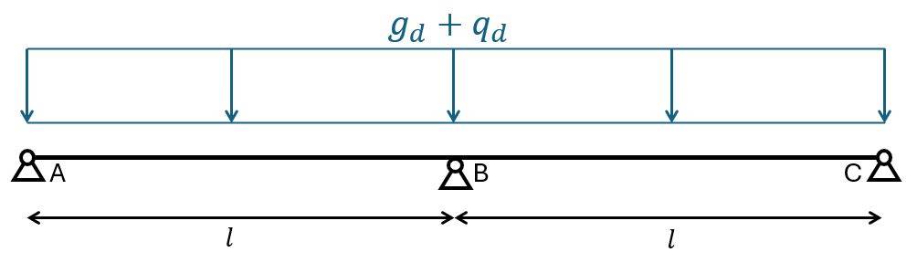
Bending moments in x-direction
In x-direction we use the static system of a 2 span continuous beam. You can find the formulas for bending moments here.
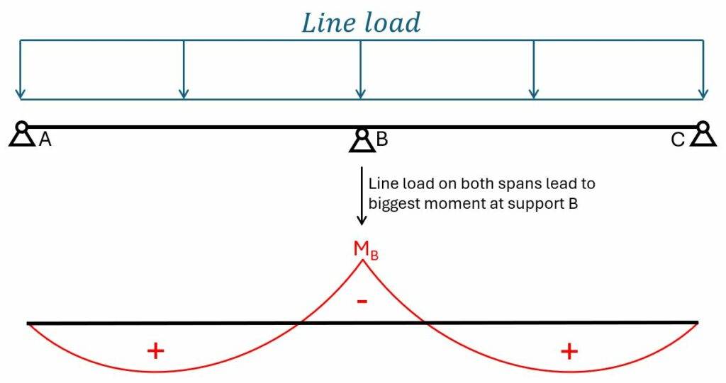
Biggest negative bending moment at middle support B
The biggest negative bending moment is found at the middle support with the biggest loads on both spans. 👇👇
$$M_{Ed.B.x} = -1/8 \cdot (g_d + q_d) \cdot l^2 = -100.9 kNm/m$$
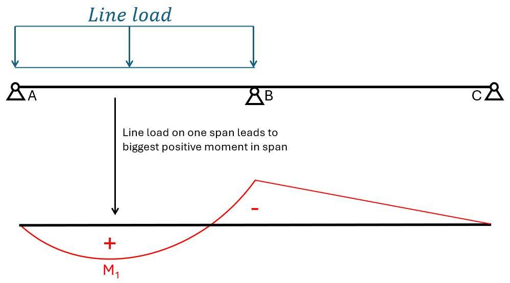
Biggest positive bending moment in span between support A and B
The biggest positive bending moment is found between support A and B with the dead load on both spans (because the dead load always acts) and the live load on 1 span. 👇👇
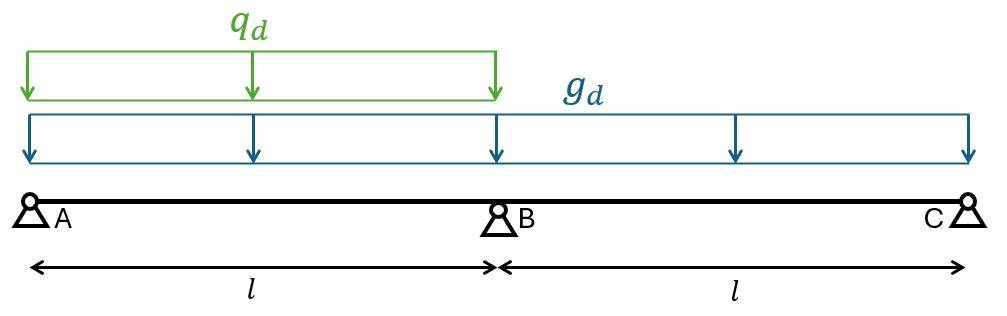
$$M_{Ed.1.x} = 9/128 \cdot g_d \cdot l^2 + 49/512 \cdot q_d \cdot l^2 = 62.1 kNm/m$$
Bending moments in y-direction
Biggest negative bending moment at middle support B
$$M_{Ed.B.y} = -1/8 \cdot (g_d + q_d) \cdot b^2 = -64.56 kNm/m$$
Biggest positive bending moment in span between support A and B
$$M_{Ed.1.y} = 9/128 \cdot g_d \cdot b^2 + 49/512 \cdot q_d \cdot b^2 = -39.75 kNm/m$$
Distribution of bending moments into column and middle strip with the equivalent frame method (EN1992-1-1 Table I.1)
The equivalent frame method divides the slabs longitudinally and transverseley into frames of the columns and the slab. We divide the slab into column and middle strips according to EN 1992-1-1 Figure I.1.
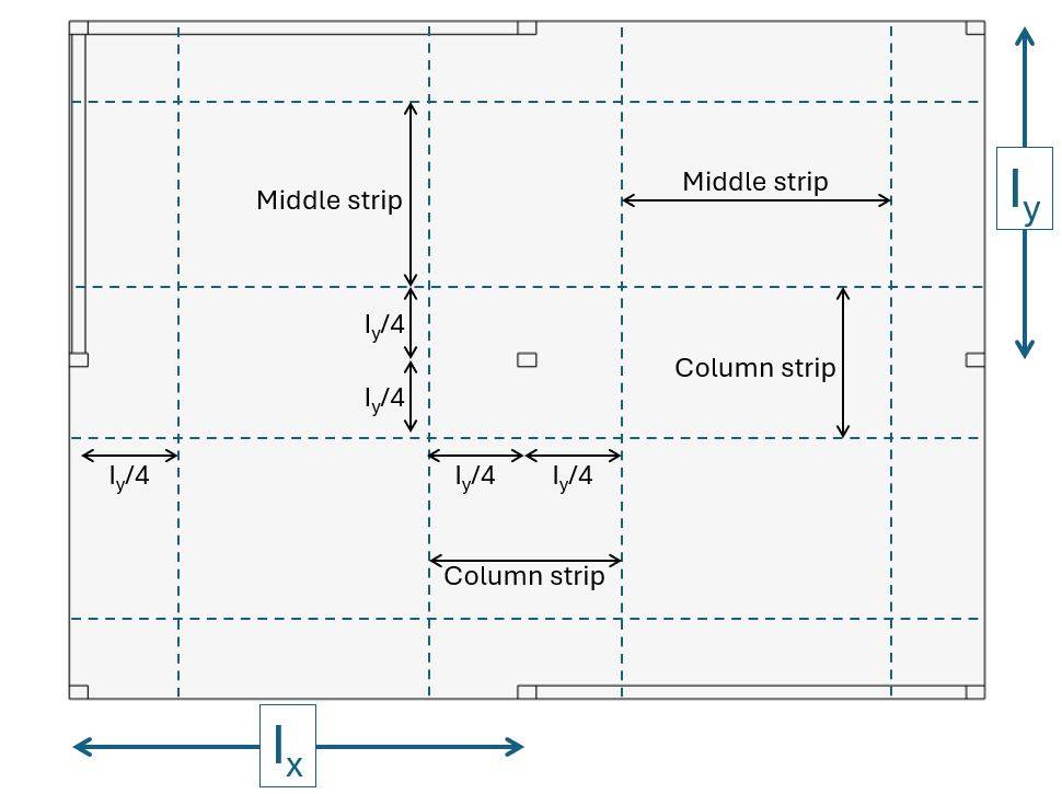
| Column spacing in x direction | Ix = l = 7.5 m |
| Column spacing in y direction | Iy = b = 6.0 m |
| Width of column strip in y direction (center column) | ly.c = Iy/2 = 3.0 m |
| Width of column strip in x direction (center column) | lx.c = Ix/2 = 3.0 m |
| Width of middle strip in y direction (center column) | ly.m = Iy/2 = 3.0 m |
| Width of middle strip in x direction (center column) | lx.m = Ix – Iy/2 = 4.5 m |
The bending moments for each strip and direction is calculated based on the panel division of the table above and a simplified apportionment of the bending moment based on EN 1992-1-1 Table I.1:
| Negative moments | Positive moments | |
| Column strip | 60 – 80% | 50 – 70% |
| Middle strip | 40 – 20% | 50 – 30% |
We’ll use the middle values that are given in EN 1992-1-1 Table I.1. So for example for the negative moments of the column strip, we’ll use 70%.
Moments in x-direction
| Column strip – negative moment | $M_{Ed.c.n.x} = M_{Ed.b.x} \cdot b \cdot 0.7 \cdot 1/l_{y.c} = 141.2 kNm/m$ |
| Middle strip – negative moment | $M_{Ed.m.n.x} = M_{Ed.b.x} \cdot b \cdot 0.3 \cdot 1/l_{y.c} = 60.5 kNm/m$ |
| Column strip – positive moment | $M_{Ed.c.p.x} = M_{Ed.1.x} \cdot b \cdot 0.6 \cdot 1/l_{y.m} = 74.5 kNm/m$ |
| Middle strip – positive moment | $M_{Ed.m.p.x} = M_{Ed.1.x} \cdot b \cdot 0.4 \cdot 1/l_{y.m} = 49.7 kNm/m$ |
Moments in y-direction
| Column strip – negative moment | $M_{Ed.c.n.y} = M_{Ed.b.y} \cdot l \cdot 0.7 \cdot 1/l_{x.c} = 113.0 kNm/m$ |
| Middle strip – negative moment | $M_{Ed.m.n.y} = M_{Ed.b.y} \cdot l \cdot 0.3 \cdot 1/l_{x.m} = 32.3 kNm/m$ |
| Column strip – positive moment | $M_{Ed.c.p.y} = M_{Ed.1.y} \cdot l \cdot 0.6 \cdot 1/l_{x.c} = 59.6 kNm/m$ |
| Middle strip – positive moment | $M_{Ed.m.p.y} = M_{Ed.1.y} \cdot l \cdot 0.4 \cdot 1/l_{x.m} = 26.5 kNm/m$ |
Now, we are ready to design the longitudinal reinforcement in the next section.
6. ULS bending verification and design of longitudinal reinforcement
The bending design of a flat slab is like for a RC beam. We’ll run through the following steps for both directions and each panel.
Assume a preliminary rebar diameter ds and calculate the effective height:
$$d = t_p – c – d_s/2$$
Depending on the direction, you might have to add the diameter of the rebars in the other direction.
$\mu$ value:
$$\mu = \frac{M_{Ed}}{d \cdot f_{cd}}$$
$\omega$ value:
$$\omega = 1 – \sqrt{1- 2 \cdot \mu}$$
Required reinforcement:
$$A_{s.req} = \frac{\omega \cdot 1m \cdot d \cdot f_{cd}}{f_{yd}}$$
X – Direction
We’ll assume the following diameter for the longitudinal reinforcement:
$$d_{s.x} = 12 mm$$
This leads to the following effective height:
$$d_x = t_p – c – d_{s.x}/2 = 219 mm$$
| $\mu$ | $\omega$ | $A_{s.req}$ [mm2/m] | Reinforcement | |
| Column strip – negative moment | 0.142 | 0.154 | 1677 | $\phi$=16/10cm |
| Middle strip – negative moment | 0.061 | 0.063 | 685 | $\phi$=12/12cm |
| Column strip – positive moment | 0.075 | 0.078 | 850 | $\phi$=12/12cm |
| Middle strip – positive moment | 0.05 | 0.051 | 559 | $\phi$=12/15cm |
Y – Direction
We’ll assume the following diameter for the longitudinal reinforcement in y-direction:
$$d_{s.y} = 12 mm$$
This leads to the following effective height:
$$d_y = t_p – c – d_{s.y}/2 – d_{s.x} = 207 mm$$
| $\mu$ | $\omega$ | $A_{s.req}$ [mm2/m] | Reinforcement | |
| Column strip – negative moment | 0.127 | 0.137 | 1406 | $\phi$=16/12cm |
| Middle strip – negative moment | 0.036 | 0.037 | 381 | $\phi$=10/15cm |
| Column strip – positive moment | 0.067 | 0.07 | 716 | $\phi$=12/15cm |
| Middle strip – positive moment | 0.03 | 0.03 | 312 | $\phi$=10/16cm |
As a last step, we’ll check minimum reinforcement according to EN 1992-1-1 9.2.1.1 (9.1N):
Minimum reinforcement EN 1992-1-1 9.2.1.1 (9.1N):
$$A_{s.min} = max(0.26 \cdot \frac{f_{ctm}}{f_{yk}} \cdot 1m \cdot d; 0.0013 \cdot 1m \cdot d = 330.3 mm^2$$
As.req is bigger than As.min for all strips in both directions except the middle strip with positive moment in y-direction. However, we chose longitudinal reinforcement of $\phi$=10/16cm which results in a reinforcement area of 491 mm2/m, which also verifies. 👍✅
We can now make a sketch of the reinforcement distribution.
Rebars in x-direction
Red = in the top of the flat slab
Blue = in the bottom of the flat slab
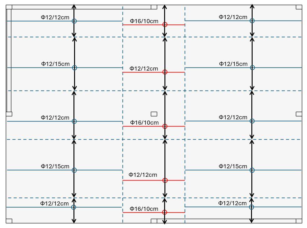
💡💡 Info:
If you are using the top reinforcement only in the column strips, then you need to add the anchorage length for the rebars according to EN 1992-1-1. Personally, I would use the same diameter and spacing for the reinforcement in the bottom for the whole width. This makes it easier to construct and you don’t have to worry about the minimum reinforcement in the column strips.
Rebars in y-direction
Red = in the top of the flat slab
Blue = in the bottom of the flat slab
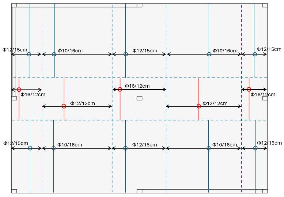
💡💡 Info:
The same comments as for the longitudinal reinforcement in x direction apply to the y direction.
7. ULS Punching Shear Verification
Punching shear is a failure that can occur in flat slabs at their point supports (columns). It’s quite an extensive calculation following EN 1992-1-1 6.4.
That’s why we have written a full article which covers the whole process step-by-step: 👇👇
8. SLS crack width verification
The crack width limit is found in EN 1992-1-1 Table 7.1N.
For a reinforced member in exposure class XC1, the crack width limit for a quasi-permanent load is set to 👇👇
$$w_{max} = 0.4mm$$
We’ll follow the following steps to calculate the crack width. It’s the same calculation that you follow when calculating the crack width of a beam.
- Neutral axis depth of the cracked section
- Quasi-permanent moment
- Stress in the reinforcement
- Calculation of the strain
- Max. crack spacing
- Crack width
1. Neutral axis depth of the cracked section
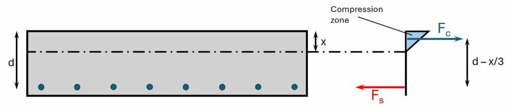
We’ll find the depth of the neutral axis by equilibrium of the first moment of areas of the tension (steel) and compression (triangle). But don’t get confused by the triangle here. When calculating the static moment of the compression zone, we only need the area of it and the lever arm is x/2.
But first, we need to calculate some parametes.
The final creep coefficient is found from EN 1992-1-1 Figure 3.1 for a considered cross-sectional area of $A_c = t_p = 1m= 0.25 m^2$, a perimeter of cross-section exposed to drying of u = 1m + 1m = 2m and a notional size of $h_0 = 2 \cdot \frac{A_c}{u} = 0.25$.
$$\phi = 2.2$$
E-modulus of concrete long-term (quasi-permanent):
$$E_{c.eff} = \frac{E_{cm}}{1 + \phi} = 10261.6 MPa$$
Long-term steel – concrete ratio:
$$\alpha_s = \frac{E_s}{E_{c.eff}} = 19.5$$
Now, we can define the equilibrium of the 1. moment of areas. 👇👇
$$A_s = A_{s.c.n}$$
$$w \cdot x \cdot \frac{x}{2} = \alpha_s \cdot A_s \cdot (d-x)$$
Solving that for x leads to
$$x = \frac{\alpha_s \cdot A_{s.c.n}}{1 m} \cdot (-1 + \sqrt{1 + \frac{2 \cdot 1m \cdot d}{\alpha_s \cdot A_s}} = 97.56 mm$$
2. Quasi-permanent moment
From the moment calculation in section 5 we can see that the biggest moment occurs at the center column in x direction.
So, we’ll calculate that moment for the quasi-permanent load qqp. We use a partial factor for the live load for offices based in the Danish Annex.
$$\psi_{2.q} = 0.2$$
$$q_{qp} = g_{k.s} + g_{k.f} + \psi_{2.q} \cdot q_k = 8.35 kN/m^2$$
Next, we’ll calculate the moment of the 2-span continuous beam in x-direction:
$$M_{qp} = 1/8 \cdot q_{qp} \cdot l^2 = 58.7 kNm/m$$
And finally, the negative moment of the column strip in x-direction:
$$M_{qp.c.n} = M_{qp} \cdot b \cdot 0.7 \cdot 1/l_{y.c} = 82.2 kNm/m$$
3. Stress in the reinforcement
We calculate the stress in the reinforcement by taking moments at the location of the compressive force.
$$\sigma_s = \frac{M_{qp.c.n}}{(d_x-x/3) \cdot A_s} = 219.2 N/mm^2$$
4. Calculation of the strain
Factor dependent on the duration of the load EN 1992-1-1 (7.10) (long-term loading)
$$k_t = 0.4$$
$$f_{ct.eff} = f_{ctm} = 2.9 MPa$$
Effective height EN 1992-1-1 7.3.2. (3)
$$h_{c.eff} = min(2.5 \cdot (h – d); \frac{h-x}{3}; h/2) = 50.8 mm$$
$$\rho_{p.eff} = \frac{A_s}{h_{c.eff} \cdot w} = 0.04$$
EN 1992-1-1 (7.9)
$$\epsilon_{sm} – \epsilon_{cm} = max(\frac{\sigma_s – k_t \cdot \frac{f_{ct.eff}}{\rho_{p.eff}} \cdot (1 + \alpha_s \cdot \rho_{p.eff})}{E_s}; 0.6 \cdot \frac{\sigma_s}{E_s}) = 0.0007$$
5. Max. crack spacing
Coefficient EN 1992-1-1 (7.11) for high bond bars
$$k_1 = 0.8$$
Coefficient EN 1992-1-1 (7.11) for bending
$$k_2 = 0.5$$
$$s_{r.max} = 3.4 \cdot c + 0.425 \cdot k_1 \cdot k_2 \cdot \frac{d_s}{\rho_{p.eff}} = 0.154m$$
Verification
$$s_{r.max} < 5 \cdot (c + \frac{d_s}{2}) = 1$$
Verification fullfilled!
6. Crack width
$$w_k = s_{r.max} \cdot \epsilon = 0.10 mm$$
Utilization
$$\eta = \frac{w_k}{w_{max}} = 0.25$$
The crack width is verified!
9. SLS Deflection Verification
The deflection calculation of reinforced concrete elements is not as straightforward as for timber or steel structures. However, according to Eurocode EN 1992-1-1 the deflection requirement is likely to be satisfied if the span – effective depth ratio is less than the values given in EN 1992-1-1 Table 7.4N.
However, this is a very conservative approach and we’ll have to increase the height of the slab to 310 mm and decrease the max. span to 6.5m to fullfill the requirement of EN 1992-1-1 Table 7.4N.
Increase of the effective height/slab by 6 cm:
$$d_x = d_x + 6 cm = 0.279m$$
Reinforcement ratio is x-direction:
$$\rho_x = \frac{A_{s.c.n}}{d_x \cdot 1m} = 0.0072$$
Ratio of span/effective depth of flat slab according to EN 1992-1-1 Table 7.4N. We have to interpolate in principle the values for a highly stressed and lightly stressed concrete element. But as we see in the following, we would increase the height of the flat slab even more. So for the sake of this tutorial, we’ll use the value of the ratio for a lightly stressed concrete element which is 24.
Max. span (as mentioned we’ll decrease the span):
$$l = 6.5m$$
Span/effective depth ratio:
$$r = l/d_x = 23.3$$
Verification
$$\frac{l}{h} = 23.3 < 24$$
Verification fullfilled!
💡💡 Info:
A better approach to verify the deflection of a flat slab would be to model the flat slab in a Finite Element program such as Autodesk Robot as it is more accurate and not as conservative as EN 1992-1-1 7.4N.
Conclusion
Et voila, the slab is verified and dimensioned for the bending moments, shear, cracks and deflection. 💯💯
If you are new to structural design, then check out more of our design tutorials where you can learn how to design elements such as: 👇👇
But now, I would like to hear from you: Are you designing a reinforced concrete slab for a uni project? Or are you renovating your own house? Tell us a bit about the structure, as we all want to learn from each other.✍️

![Pad Foundation In Clay [Design Of Soil And Concrete]](https://www.structuralbasics.com/wp-content/uploads/2023/05/Pad-foundation-design-clay-768x439.jpg)

![Timber Flat Roof Beam Design [Structural Calculation]](https://www.structuralbasics.com/wp-content/uploads/2022/04/Timber-flat-roof-design-768x439.jpg)