Steel Column Design – Complete Guide (2026)
Designing steel columns is something structural engineering students learn early in university as steel is one of the 3 most used structural building materials and columns the second most used static system – after beams.
Later on, structural engineers do steel column design over and over.
So in this post we’ll show you, step-by step, how to design axially loaded steel columns with a practical example, what loads can act on a column and how to classify a steel Cross-section according to the Steel Eurocode EN 1993-1-1.
Not much more talk, let’s dive into it.
📃 Process of Steel Column Design
Before we dive into the nerdy calculations, it’s good to get an overview of the steps that need to be taken to design a steel column – in this case, an axially loaded column.
- Calculate characteristic loads that act on the column
- Load combinations
- Define properties of steel column
- Cross-Section Classification
- Compression Verification
- Flexural Buckling Verification
However, we dive a bit deeper and explain concepts, such as different static systems of columns along the way.
🙋♀️ Example Structures of Steel Columns
Steel columns are used in
- Warehouse structures
- Temporary event structures (tents, stages, etc.)
- Buildings
- Scaffolding
- Renovation projects as “reinforcement” of existing structure
- Factories
- Steel towers
to name a few.
The use of steel is also highly dependent on the country. In some countries steel structures are common, in some they’re not.
👆 Static systems of steel columns
There is a variety of different static systems that the structural engineer can choose from, and often the columns act together with beams as frames.
Here are the most common static systems of steel columns that are used in structural design.
Simply Supported Column
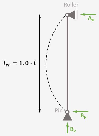
Support types
Roller & Pin
Reactions
Roller: Horizontal
Pin: Vercial & Horizontal
Buckling length
$l_{cr} = 1.0 \cdot l$
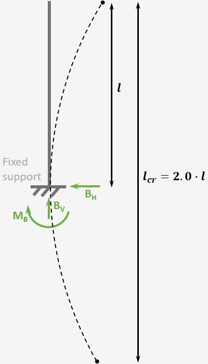
Cantilever Column
Support types
1 Fixed support
Reactions
Fixed support: Horizontal, Vertical & Moment
Buckling length
$l_{cr} = 2.0 \cdot l$
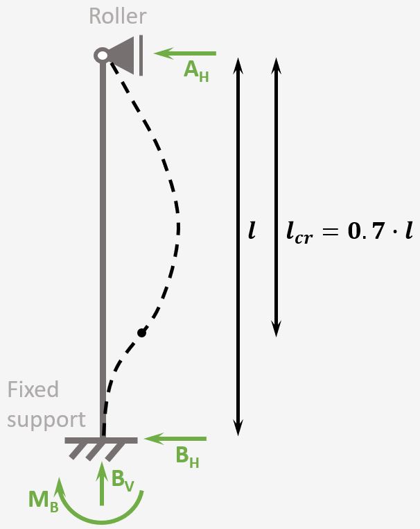
Column with 1 fixed and 1 roller support
Support types
1 Fixed support & 1 Roller support
Reactions
Fixed support: Horizontal, Vertical Reaction force & Moment
Roller support: Horizontal Reaction force
Buckling length
$l_{cr} = 0.7 \cdot l$
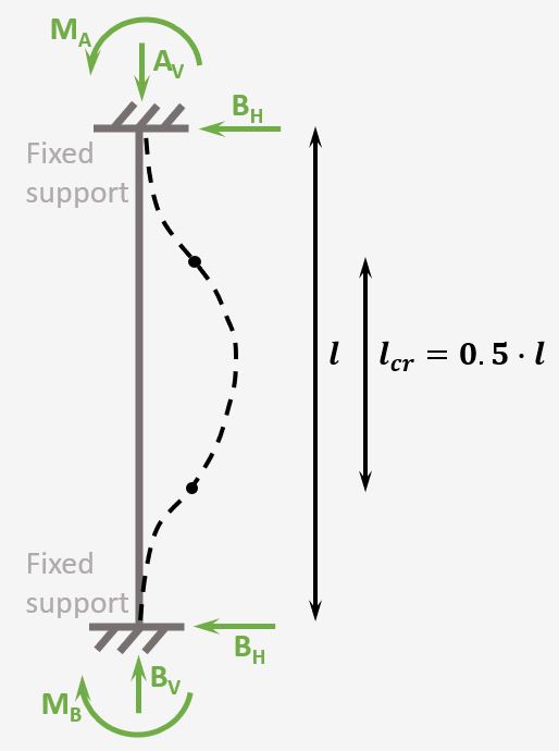
Column with 2 fixed supports
Support types
2 Fixed supports
Reactions
Fixed support: Horizontal, Vertical & Moment
Buckling length
$l_{cr} = 0.5 \cdot l$
It’s important to know about the different static systems, since each type of column has a different buckling length, which influences the buckling resistance significantly❗
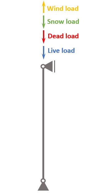
For this tutorial, we assume to design a simply supported column on the inside of a building structure, which could be a supermarket. The column will not be exposed to wind.
The following picture shows where the column could be used.

⬇️ Characteristic loads of steel column
The loads of a structure depend on its location, geometry, building type and other factors.
We’ll assume in this tutorial that we design the column of a 1-storey building, such as a supermarket.
Now on a 1-storey building, the following loads act:
- Dead load of structural and non-structural elements
- Live load of the roof
- Snow load and
- Wind load
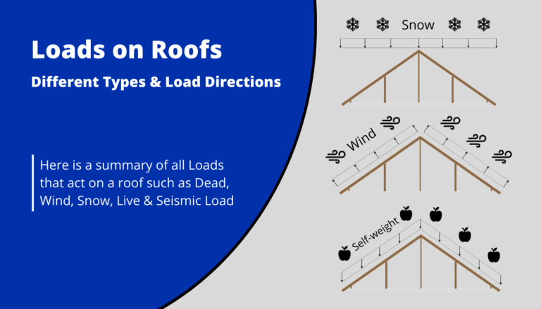
We’ll do a lot of assumptions in this tutorial, but if you want to learn more about loads on roofs, you can check out this article.
Load transfer
❗ The following load transfer explanation works if the building is a traditional structure with simply supported beams and columns❗
- Live, Snow, Wind and dead load (self-weight of roofing) are applied as area loads [kN/m2] on the roof.
The roof could for example be a trapezoidal roof sheet. This roof sheet transfers the loads to the beams which support the sheets. - By multiplying the area loads (live, snow, wind, dead load) with the spacing of the beams, line loads are calculated. These line load can now be applied to the beams.
- The center reaction force of the beam system is then the characteristic vertical load that is applied to the column.
The following characteristic load values are assumptions.
| $g_{k}$ | 167 kN | Characteristic value of dead load |
| $q_{k}$ | 77 kN | Characteristic value of live load |
| $s_{k}$ | 27 kN | Characteristic value of snow load |
| $w_{k}$ | -30 kN | Characteristic value of wind load |
➕ Load combinations
Load combinations combine several load cases and multiply the characteristic loads with safety factors.
Luckily we have already written an extensive article about what load combinations are and how we use them. In case you need to brush up on it, you can read the blog post here.
ULS Load combinations
| LC1 | $1.35 * 167 kN $ | $225.5 kN$ | |
| LC2 | $1.35 * 167 kN + 1.5 * 77 kN$ | $340.95 kN$ | |
| LC3 | $1.35 * 167 kN + 1.5 * 77 kN + 0.7 * 1.5 * 27 kN$ | $369.3 kN$ | |
| LC4 | $1.35 * 167 kN + 0 * 1.5 * 77 kN + 1.5 * 27 kN$ | $265.95 kN$ | |
| LC5 | $1.35 * 167 kN + 1.5 * 77 kN + 0.7 * 1.5 * 27 kN + 0.6 * 1.5 * (-30 kN) $ | $342.3 kN$ | |
| LC6 | $1.35 * 167 kN + 0 * 1.5 * 77 kN + 1.5 * 27 kN + 0.6 * 1.5 * (-30 kN) $ | $238.95 kN$ | |
| LC7 | $1.35 * 167 kN + 0 * 1.5 * 77 kN + 0.7 * 1.5 * 27 kN + 1.5 * (-30 kN) $ | $208.8 kN$ | |
| LC8 | $1.35 * 167 kN + 1.5 * 27 kN $ | $265.95 kN$ | |
| LC9 | $1.35 * 167 kN + 1.5 * (-30 kN) $ | $108.45 kN$ | |
| LC10 | $1.35 * 167 kN + 1.5 * 77 kN + 0.6 * 1.5 * (-30 kN) $ | $313.95 kN$ | |
| LC11 | $1.35 * 167 kN + 1.5 * (-30 kN) + 0.7 * 1.5 * 27 kN $ | $208.8 kN$ | |
| LC12 | $1.35 * 167 kN + 1.5 * 27 kN + 0.6 * 1.5 * (-30 kN)$ | $238.95 kN$ |
👉 Steel Column properties
In this tutorial, we’ll design a steel column which has the Cross-section of a HEB120. We’ll use the Cross-section properties from eurocodeapplied.com.
It’s btw a really good resource for all kind of steel cross-section properties.
We furthermore specify that the column is of steel class S355.
Here are the geometrical properties of a HEB120 S355 Cross-section we are gonna use.
| Width | $b=120mm$ |
| Height | $h=120mm$ |
| Web thickness | $t_w = 6.5mm$ |
| Flange thickness | $t_f = 11mm$ |
| Root radius | $r = 12mm$ |
| Radius of inertia – strong axis | $i_y = 50.4mm$ |
| Radius of inertia – weak axis | $i_z = 30.6mm$ |
| Moment of inertia – strong axis | $I_y = 8.64 \cdot 10^6 mm^4$ |
| Moment of inertia – weak axis | $I_z = 3.18 \cdot 10^6 mm^4$ |
| Cross-sectional area | $A = 3401 mm^2$ |
Here are the properties of Steel S355
| E-modulus | $E = 0.21 \cdot 10^6 MPa$ |
| Yield strength | $f_y = 355 MPa$ |
Now, we are all set to design the steel column 🔥.
🕵️♂️ Cross-section Classification
Steel Cross-sections have to be classified in order to find out if the specific element can be calculated with plastic or elastic analysis.
EN 1993-1-1 5.5.2 (1) describes the differences between the 4 classes.
In order to find out if the class of a column with cross-section HEB140 we need to follow the checks of EN 1993-1-1 Table 5.2. So let’s do that.
We differentiate between outstand flange and internal compression parts.
Internal compression parts (EN 1993-1-1 Table 5.2 (sheet 1 of 3))
When we look at the table, we see that for a HEB140 cross-section we need to first define the parameters c and t.
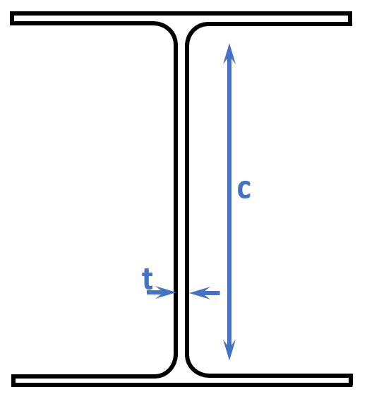
$$t = t_w = 6.5mm$$
$$c = h-2 \cdot t_f – 2 \cdot r = 120mm – 2 \cdot 11mm – 2 \cdot 12mm = 74mm$$
Now in the table we need to pick the 2nd column because due to an axial load the cross-section is fully in compression.
A beam for example would be the 1st column because bending moments lead to tension and compression in the cross-section.
$$\frac{c}{t} = 11.4$$
We can see from the table that if this value is greater than $33 \cdot \varepsilon$ then the cross-section belongs to class 1. $\varepsilon$ is calculated as
$$\varepsilon = \sqrt{\frac{235MPa}{f_y}} = 0.81$$
Check
$$33 \cdot \varepsilon = 26.8 > 11.4$$
The internal compression parts of a HEB120 can therefore be calculated as Cross-section class 1.
Outstand flange (EN 1993-1-1 Table 5.2 (sheet 2 of 3))
As for the internal compression parts (the web), we need to define the parameters c and t for the flange classification.
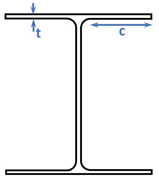
$$t = t_f = 11mm$$
$$c = \frac{b – t_w – 2 \cdot r}{2} = \frac{120mm – 6.5mm – 2 \cdot 12mm}{2} = 44.75mm$$
Let’s calculate the ratio again.
$$\frac{c}{t} = 4.1$$
Check
$$9 \cdot \varepsilon = 7.32 > 4.1$$
The outstand flange of a HEB120 can therefore be calculated as Cross-section class 1.
Overall can be said that in the design the plastic cross-sectional properties can be utilized.
✍️ ULS Compression Verification
In the ULS (ultimate limit state) Design we verify the stresses in the steel members due to bending, shear, normal forces and buckling.
However, since the column is only exposed to axial forces, we don’t verify the column for bending.
The compressive design resistance force is calculated with EN 1993-1-1 (6.10) as
$$N_{c.Rd} = \frac{A \cdot f_y}{\gamma_{M0}}$$
with
$\gamma_{M0} = 1.1$ Partial factor found in the National Annex. Note that the value of 1.1 is taken from the danish national annex. You need to check the value of $\gamma_{M0}$ for your own country.
$$N_{c.Rd} = \frac{3401mm^2 \cdot 3.55 \cdot 10^5 \frac{kN}{m^2}}{1.1} = 1097.6 kN$$
The biggest design axial force is found from Load combination 3 as
$$N_{Ed} = 369.3 kN$$
Utilization check
$$\eta = \frac{N_{Ed}}{N_{c.Rd}} = \frac{369.3 kN}{1097.6 kN} = 33.7\%$$
The Cross-section is 33.7% utilized for compression.
👩🏫 ULS Flexural buckling about y-axis
The static system of the column is key in the buckling verification, as it defines the buckling length $l_{cr}$.
As we have seen in the beginning of the article, we chose the static system of a simply supported column/beam which has a buckling length of
$$l_{cr} = 1.0 \cdot l = 3.0m$$
Slenderness (EN 1993-1-1 6.3.1.3 (1))
$$\lambda_1 = \pi \cdot \sqrt{\frac{E}{f_y}} = 76.41$$
Non-dimensional slenderness (EN 1993-1-1 (6.50))
$$\lambda = \frac{l_{cr}}{i_y} \cdot \frac{1}{\lambda_1}= 0.78$$
The buckling curve is found to be b for a HEB120 about the y-axis from EN 1993-1-1 Table 6.2.
From the buckling curve b the Imperfection factor is found in EN 1993-1-1 Table 6.1.
$$\alpha = 0.34$$
More buckling reduction factors are calculated with EN 1993-1-1 (6.49)
$$\Phi = 0.5 \cdot (1 + \alpha \cdot (\lambda – 0.2) + \lambda^2) = 0.90$$
$$\chi = \frac{1}{\Phi + \sqrt{\Phi^2 – \lambda^2}} = 0.74$$
The design buckling resistance around the y-axis is calculated with EN 1993-1-1 (6.47)
$$N_{b.Rd} = \frac{\chi \cdot A \cdot f_y}{\gamma_{M1}}$$
with
$\gamma_{M1} = 1.2$ Partial factor found in the National Annex. Note that the value of 1.2 is taken from the danish national annex. You need to check the value of $\gamma_{M1}$ for your own country❗
$$N_{b.Rd} = \frac{0.74 \cdot 3401mm^2 \cdot 3.55 \cdot 10^5 \frac{kN}{m^2}}{1.2} = 741.8 kN$$
Utilization check
$$\eta = \frac{N_{Ed}}{N_{b.Rd}} = \frac{369.3 kN}{741.8 kN} = 49.8\%$$
The Cross-section is 49.8% utilized for buckling around the y-axis.
📱 ULS Flexural buckling about z-axis
As for the cross-section around the y-axis, we assume that the buckling length around the z-axis is the same.
$$l_{cr} = 1.0 \cdot l = 3.0m$$
❗Be careful here. This is not always the case. The buckling length around the z-axis would be just half if other steel profiles are attached to the columns at midspan❗
Slenderness (EN 1993-1-1 6.3.1.3 (1))
$$\lambda_1 = \pi \cdot \sqrt{\frac{E}{f_y}} = 76.41$$
Non-dimensional slenderness (EN 1993-1-1 (6.50))
$$\lambda = \frac{l_{cr}}{i_z} \cdot \frac{1}{\lambda_1}= 1.28$$
The buckling curve is found to be c for a HEB120 about the z-axis from EN 1993-1-1 Table 6.2.
From the buckling curve c the Imperfection factor is found in EN 1993-1-1 Table 6.1.
$$\alpha = 0.49$$
More buckling reduction factors are calculated with EN 1993-1-1 (6.49)
$$\Phi = 0.5 \cdot (1 + \alpha \cdot (\lambda – 0.2) + \lambda^2) = 1.59$$
$$\chi = \frac{1}{\Phi + \sqrt{\Phi^2 + \lambda^2}} = 0.40$$
The design buckling resistance around the y-axis is calculated with EN 1993-1-1 (6.47)
$$N_{b.Rd} = \frac{\chi \cdot A \cdot f_y}{\gamma_{M1}}$$
with
$\gamma_{M1} = 1.2$ Partial factor found in the National Annex. Note that the value of 1.2 is taken from the danish national annex. You need to check the value of $\gamma_{M1}$ for your own country❗
$$N_{b.Rd} = \frac{0.4 \cdot 3401mm^2 \cdot 3.55 \cdot 10^5 \frac{kN}{m^2}}{1.2} = 398.5 kN$$
Utilization check
$$\eta = \frac{N_{Ed}}{N_{b.Rd}} = \frac{369.3 kN}{398.5 kN} = 92.7\%$$
The Cross-section is 92.7% utilized for buckling around the z-axis.
Once the compression, buckling around y-axis and z-axis checks are verified, we successfully designed the column💯.
If you are new to structural design, then check out more of our design tutorials where you can also learn how to design wood elements such as
But now, I would like to hear from you: Have you already designed a steel column in university or at your work? Tell us a bit about the structure, as we all want to learn from each other.✍️
![Reinforced Concrete Column Design [2026]](https://www.structuralbasics.com/wp-content/uploads/2024/02/RC-column-design-768x439.jpg)