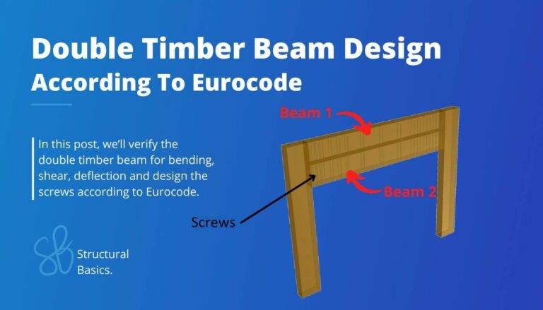
11 Types of Trusses [The MOST Used]
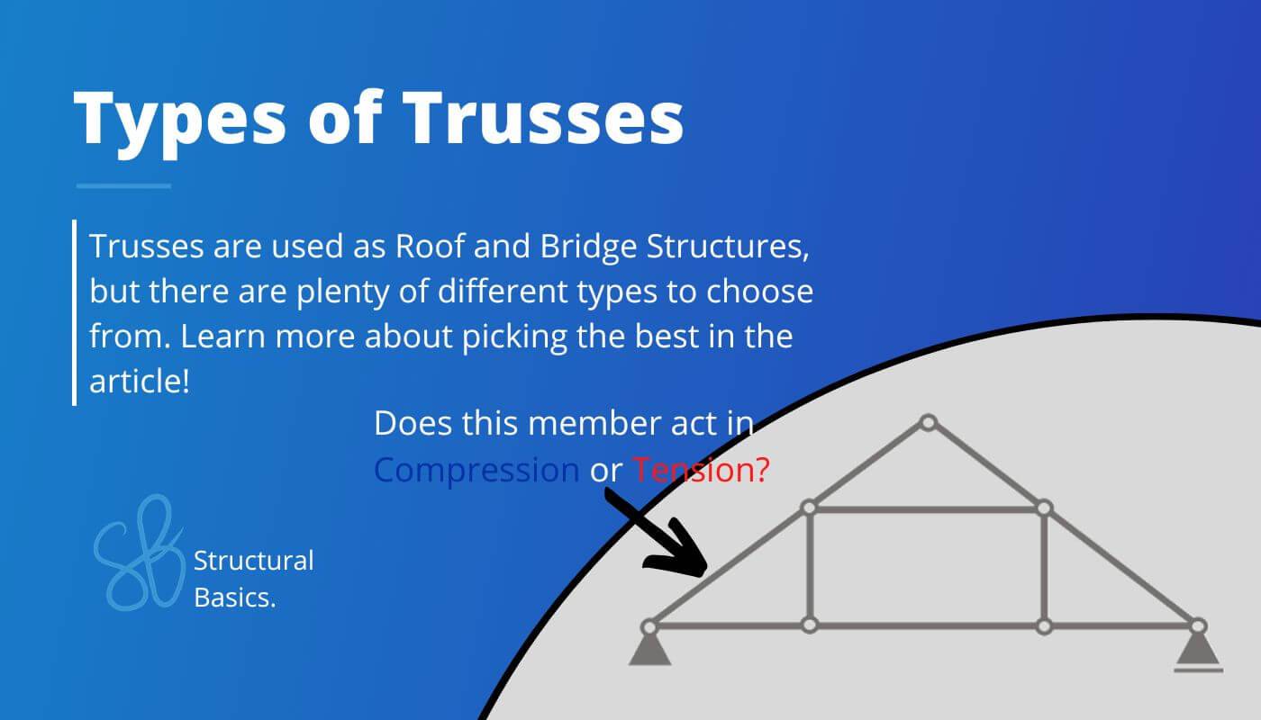
Trusses are commonly used in roof and bridge structures, but there are a lot of different types.
Also, not every type suits the purpose of the structure.
And before we can design a truss like a timber truss roof, we need to pick the best truss type.
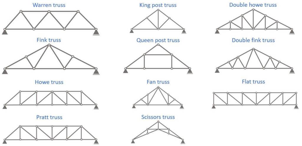
So in this post, we’ll show all types of trusses, their static systems, which members act in compression or tension and other features.
Without further ado. Let’s talk TRUSSES. 🚀🚀
What Is a Truss?
Trusses are structural elements that can carry loads with relatively long spans compared to beams. Trusses are characterized by having tensions and compression members. These structures are often used in roof, floor and bridge structures.
Let’s have a look at one example of a truss and its different members. In the picture, you can see the Howe truss, which we will explain later more in detail.
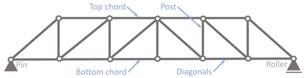
- Top chord
- Bottom chord
- Diagonals (sometimes called strut or tie depending on compression or tensions)
- Post
Different Types of Truss Structures
Trusses are primarily used in a building to transfer the roof loads such as wind, snow, dead and live load to the walls or columns which will then transfer the loads further down to the foundation and soul.
From my personal experience as a structural engineer and calculating many different types of trusses, I learned that each truss type has different characterisics and benefits.
In the following I’ll share the knowledge I gained about each truss type.
1. Warren Truss
The Warren truss is a very familiar type for most of us. They are often used for steel railway bridges.
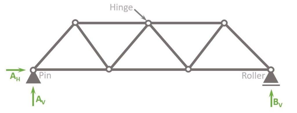
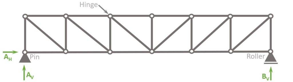
In the picture above you can see a static system of the Warren truss which has hinges at every connection.
However, nowadays, the top and bottom chords are often manufactured as one piece and due to advanced Finite Element programs it’s become easy to design trusses with fixed connections.
You are maybe wondering why the connection type is so important?
It’s because trusses with hinges only are statically determinate, which means that we can calculate the internal forces by hand.
The Warren truss with fixed connections however can’t be calculated with the 3 equilibrium equations because it’s statically indeterminate.
So, be aware that the type of connection has an influence on the design of the truss.
Let’s have a look at some of the key features of the Warren Truss.
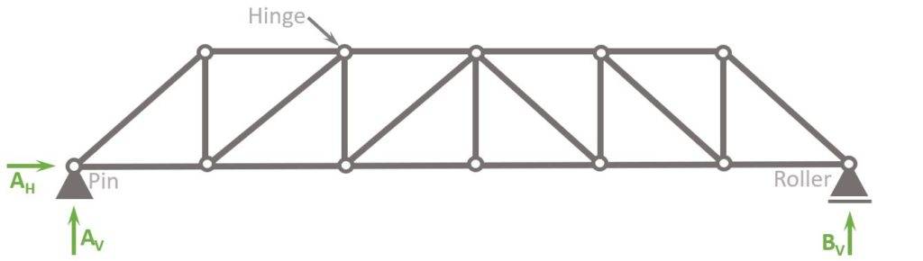
Static System
Support types
1 Pin and 1 Roller support
Reactions
Pin support: Horizontal AH and vertical reaction force AV
Roller support: Vertical reaction force BV
Loads
In most cases the Warren truss is used as a bridge where the load (dead and traffic load) is applied on the deck which distributes the load to the bottom chord
Tension members
Bottom chord, diagonals (see picture below)
Compression members
Top chord, diagonals (see picture below)
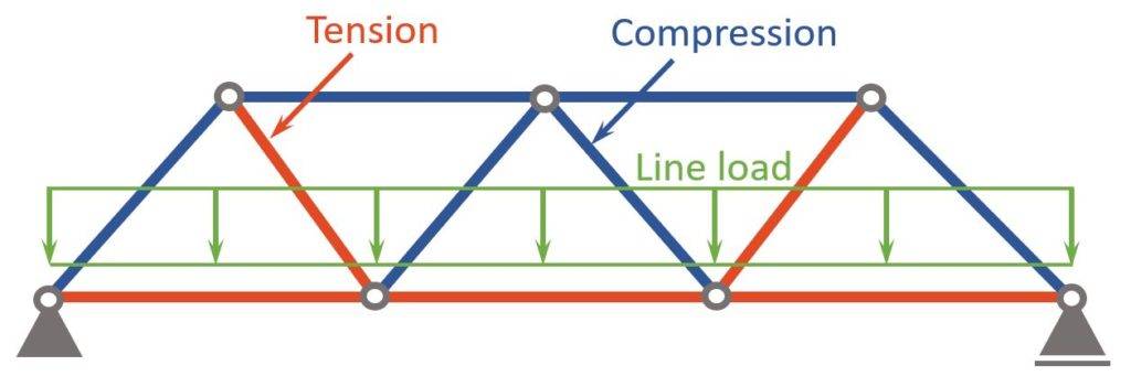
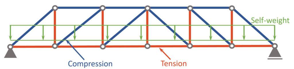
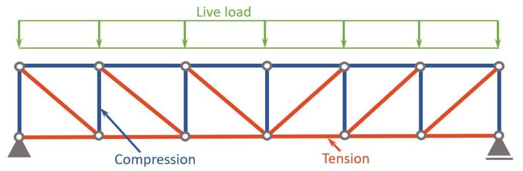
Compression and tension members of Warren truss
In the case that the Warren truss is used as a railway bridge, the static system could look like in the picture below.
A line load which represents the self-weight of the bridge itself and the traffic load is applied to the bottom chord.
The line load leads to compression in the top and tension in the bottom chord.
The diagonals are in tension 🔴 and compression 🔵, as you can see in the picture below.
Where are Warren trusses used?
- Railway bridges
2. Fink Truss
The Fink Truss is mainly used for roof structures, where the dead, snow and wind loads are distributed from the inclined top chord to the diagonals, bottom chord and then finally the pin and roller support.
It is characterized by its inclined top chords, which are supported roughly at midspan by 2 diagonals.
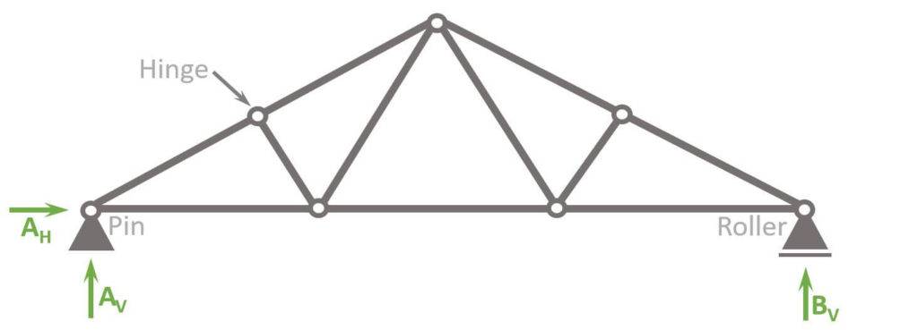
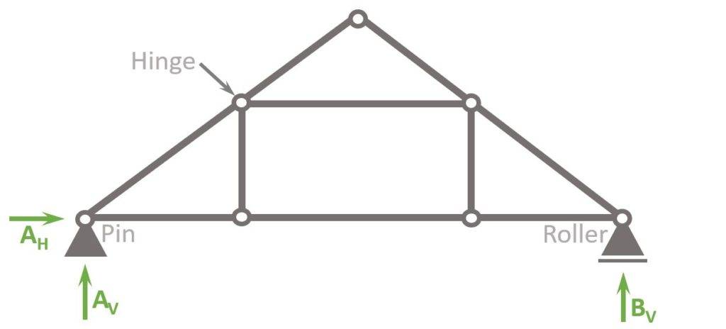
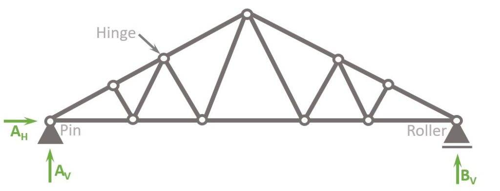
In the static system above, all connections are modelled as hinges, which makes the structure statically determinate and easy to calculate by hand.
However, the top chord is often one element and then a continuous element is more realistic.
Let’s check out some of the key features of the Fink Truss.
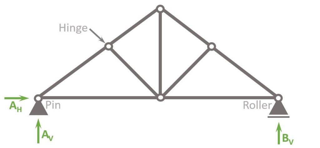
Static System
Support types
1 Pin and 1 Roller support
Reactions
Pin support: Horizontal AH and vertical reaction force AV
Roller support: Vertical reaction force BV
Loads
In most cases the Fink truss is used as a roof where the loads (dead, live, wind and snow load) are applied on the top chord.
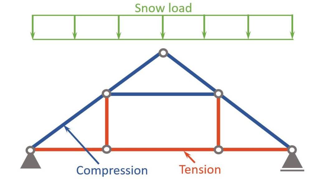
Tension members
Bottom chord, inner diagonals (see picture below)
Compression members
Top chord, outer diagonals
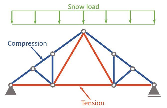
Compression and tension members of Fink Truss
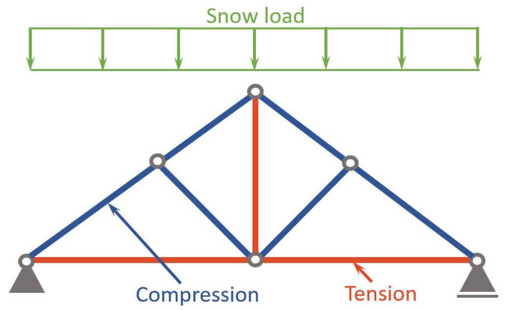
In the case that the Fink truss is used as a roof structure, the static system could look like in the picture below.
A line load which represents the self-weight of the roof itself (tiles, insulation, etc.) is applied to the top chord.
The line load leads to compression in the top and tension in the bottom chord.
The diagonals are in tension 🔴 and compression 🔵, as you can see in the picture below.

❗Be aware that the snow and wind load both get applied differently than the self-weight. Read our extensive guide about roof loads to learn more.
Where are Fink Trusses used?
- Roof structures
3. Howe Truss
The Howe Truss is mainly used for bridge and roof structures.
When used as a roof structure, the loads are applied on the top chord of the truss.
That’s different if it’s used as a bridge structure, because in most cases the loads are now applied to the bottom chord.
The Howe truss is characterized by its horizontal top and bottom chords, which are connected by an inclined diagonal.
The nodes/hinges are connected by vertical members and diagonal members, which are “outward” facing.
Let’s check out some of the key features of the Howe Truss.
Static System
Loads
Roof structures: Loads (dead, live, wind and snow load) are applied on the top chord.
Bridge structure: Load (dead and traffic load) are applied on the bottom chord.
Tension members
Bottom chord, vertical members (see picture below)
Compression members
Top chord, diagonals
Support types
1 Pin and 1 Roller support
Reactions
Pin support: Horizontal AH and vertical reaction force AV
Roller support: Vertical reaction force BV
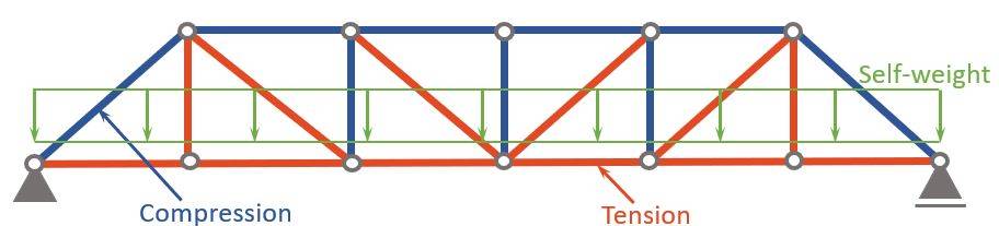
Compression and tension members of Howe Truss
In the case that the Howe truss is used as a bridge structure, the static system could look like in the picture below.
A line load which represents the self-weight of the bridge deck is applied to the bottom chord.
The line load leads to compression in the top and tension in the bottom chord.
The diagonals/verticals are in tension 🔴 and compression 🔵, as you can see in the picture below.
Where are Howe Trusses used?
- Roof structures
- Bridge structures
4. Pratt Truss

The Pratt Truss is very similar to the Howe truss. But instead of having the diagonals outwards facing, they are facing inwards.
As for Howe trusses, pratt trusses are used in bridge and roof constructions.
The Pratt truss is characterized by its horizontal top and bottom chords, which are connected by an inclined diagonal.
The nodes/hinges are connected by vertical members and diagonal members, which are “outward” facing.
Let’s check out some of the key features of the Pratt Truss.
Static System
Loads
Roof structures: Loads (dead, live, wind and snow load) are applied on the top chord.
Bridge structure: Load (dead and traffic load) are applied on the bottom chord.
Tension members
Bottom chord, diagonals, outer posts
Compression members
Top chord, posts except outer posts
Support types
1 Pin and 1 Roller support
Reactions
Pin support: Horizontal AH and vertical reaction force AV
Roller support: Vertical reaction force BV
Compression and tension members of Pratt Truss
In the case that the Pratt truss is used as a bridge structure, the static system could look like in the picture below.
A line load which represents the self-weight of the bridge deck is applied to the bottom chord.
The line load leads to compression in the top and tension in the bottom chord.
The diagonals/verticals are in tension 🔴 and compression 🔵, as you can see in the picture below.
Where are Pratt Trusses used?
- Roof structures
- Bridge structures
5. King Post Truss
King post trusses are primarily used in timber roof structures, where the loads (dead, live, snow and wind) act on the 2 inclined rafters connecting the supports and the ridge.
The vertical central member connecting the bottom chord and the ridge is the king post, and the diagonals are called struts.
A tie beam supports the struts and the king post at midspan, transferring the loads to the supports.
Now, let’s check out some of the key features of the King Post Truss.
Static System
Loads
Roof structures: Loads (dead, live, wind and snow load) are applied on the 2 outer inclined rafters.
Tension members
Bottom tie beam, King Post
Compression members
Rafters, diagonal struts
Support types
1 Pin and 1 Roller support
Reactions
Pin support: Horizontal AH and vertical reaction force AV
Roller support: Vertical reaction force BV
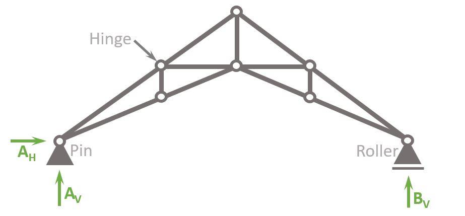
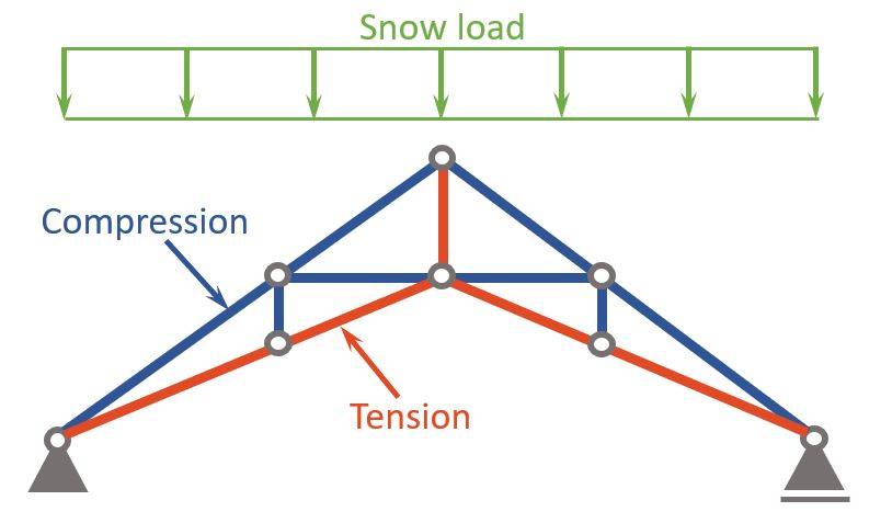
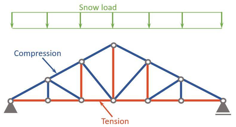
Compression and tension members of King Post Truss
In the case that the King post truss is used as a roof structure, the static system could look like in the picture below.
A line load which represents the snow load is applied to the rafters.
❗Be careful with the load direction: Dead, wind and snow load are applied differently to inclined members. Check out this guide if you want to learn more about it.
The line load leads to compression 🔵 in the rafters and the stuts, while the bottom beam and the king post act in tension 🔴.
Where are King Post Trusses used?
- Roof structures
6. Queen Post Truss
Compared to the king post truss has the Queen Post Truss less diagonals and more vertical members.
Instead of having 1 king posts, this truss has 2 queen posts – the 2 vertical bars.
Loads such as self-weight, wind, snow and live load apply on the inclined rafters, which then distribute the loads through the various members down to the 2 supports.
The straining beam is the top horizontal member, while the lower bar is called tie beam.
💡Be aware, that there are other variants of the queen post truss with diagonals from the tie beam to the rafter or with a vertical post from the ridge to the centre of the straining beam.
So, let’s check out some of the key features of the Queen Post Truss.
Static System
Loads
Roof structures: Loads (dead, live, wind and snow load) are applied on the 2 outer inclined rafters.
Tension members
Bottom tie beam, Queen Posts
Compression members
Rafters, straining beam
Support types
1 Pin and 1 Roller support
Reactions
Pin support: Horizontal AH and vertical reaction force AV
Roller support: Vertical reaction force BV
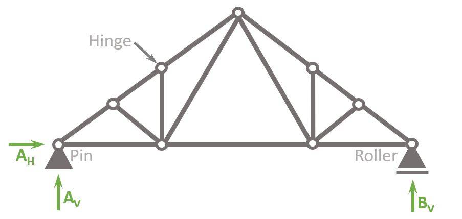
Compression and tension members of Queen Post Truss
In the case that the Queen post truss is used as a roof structure, the static system could look like in the picture below.
A line load which represents the snow load is applied to the rafters.
❗Be careful with the load direction: Dead, wind and snow load are applied differently to inclined members. Check out this guide if you want to learn more about it.
The line load leads to compression 🔵 in the rafters and the straining beam, while the bottom beam and the queen posts act in tension 🔴.
Where are Queen Post Trusses used?
- Roof structures
7. Flat Truss
Compared to the previous trusses, are flat trusses used in buildings to support floors.
Loads such as self-weight and live load apply on the top chord, which then distribute the loads through the various members down to the 2 supports.
The flat truss is characterized by having vertical members at both ends.
So, let’s check out some of the key features of the Flat Truss.
Static System
Loads
Floor structures: Loads (dead and live load) are applied on the top chord.
Tension members
Bottom chord, diagonals
Compression members
Top chord, vertical members
Support types
1 Pin and 1 Roller support
Reactions
Pin support: Horizontal AH and vertical reaction force AV
Roller support: Vertical reaction force BV
Compression and tension members of Flat Truss
In the case that the flat truss is used as a floor support structure, the static system could look like in the picture below.
A line load which represents the live load is applied to the top chords (horizontal beams).
The line load leads to compression 🔵 in the top horizontal beam and the vertical members, while the bottom beam and the diagonals act in tension 🔴.
Where are Flat Trusses used?
- Roof structures
- Floor/slab support
8. Scissors Truss
The Scissors truss definitely has additional aesthetic features to its shape.
It’s mainly used as a roof structures where loads such as self-weight, snow, wind and live load apply on the top chord, which then distribute the loads through the various members down to the 2 supports.
The flat truss is characterized by having both the top and the bottom chord inclined.
So, let’s check out some of the key features of the Scissors Truss.
Static System
Loads
Roof structures: Loads (dead, snow, wind and live load) are applied on the top chord.
Tension members
Bottom chord, top vertical post
Compression members
Top chord, outer vertical members, horizontal beam
Support types
1 Pin and 1 Roller support
Reactions
Pin support: Horizontal AH and vertical reaction force AV
Roller support: Vertical reaction force BV
Compression and tension members of Scissors Truss
In the case that the scissors truss is used as a roof structure, the static system could look like in the picture below.
A line load which represents the snow load is applied to the top chords.
The line load leads to compression 🔵 in the top chords, the horizontal bars and the 2 outer vertical bars, while the bottom chord and top vertical post act in tension 🔴.
Where are Scissors Trusses used?
- Roof structures
9. Fan Truss
The fan truss is mainly used as a roof structures where loads such as self-weight, snow, wind and live load apply on the top chord, which then distribute the loads through the various members down to the 2 supports.
It’s characterized by connecting 5 bars to 1 node in the bottom chord.
So, let’s check out some of the key features of the Fan Truss.
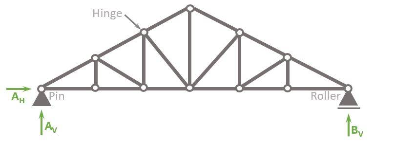
Static System
Loads
Roof structures: Loads (dead, snow, wind and live load) are applied on the inclined top chord.
Tension members
Bottom chord, inner diagonals
Compression members
Top inclined chord, outer diagonal members, vertical posts
Support types
1 Pin and 1 Roller support
Reactions
Pin support: Horizontal AH and vertical reaction force AV
Roller support: Vertical reaction force BV
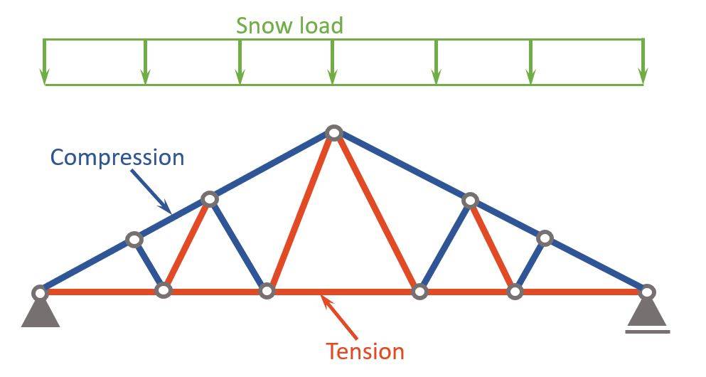
Compression and tension members of Fan Truss
In the case that the fan truss is used as a roof structure, the static system could look like in the picture below.
A line load which represents the snow load is applied to the top inclined chords.
The line load leads to compression 🔵 in the top chords, the outer diagonals and the vertical posts, while the bottom chord and inner diagonals act in tension 🔴.
Where are Fan Trusses used?
- Roof structures
10. Double Fink Truss
The double fink truss is mainly used as a roof structures where loads such as self-weight, snow, wind and live load apply on the inclined top chords, which then distribute the loads through the various members down to the 2 supports.
It’s characterized by having only diagonal members, aside from the top and bottom chords.
So, let’s check out some of the key features of the Double Fink Truss.
Static System
Loads
Roof structures: Loads (dead, snow, wind and live load) are applied on the inclined top chord.
Tension members
Bottom chord, diagonals inclined towards the center
Compression members
Top chord, diagonals inclined towards the supports
Support types
1 Pin and 1 Roller support
Reactions
Pin support: Horizontal AH and vertical reaction force AV
Roller support: Vertical reaction force BV
Compression and tension members of Double Fink Truss
In the case that the double fink truss is used as a roof structure, the static system could look like in the picture below.
A line load which represents the snow load is applied to the top inclined chords.
The line load leads to compression 🔵 in the top chords and the diagonals inclined towards the outside, while the bottom chord and diagonals inclined towards the center act in tension 🔴.
Where are Double Fink Trusses used?
- Roof structures
11. Double Howe Truss
The double howe truss is mainly used as a roof structures where loads such as self-weight, snow, wind and live load apply on the inclined top chords, which then distribute the loads through the various members down to the 2 supports.
Compared to the howe truss, the double howe truss has double as many diagonal member and posts. That’s where “double” in the name comes from.
It’s characterized by having outwards facing diagonal members and vertical posts.
So, let’s check out some of the key features of the Double Howe Truss.
Static System
Loads
Roof structures: Loads (dead, snow, wind and live load) are applied on the inclined top chord.
Tension members
Bottom chord, inner posts
Compression members
Top chord, diagonals, outer posts
Support types
1 Pin and 1 Roller support
Reactions
Pin support: Horizontal AH and vertical reaction force AV
Roller support: Vertical reaction force BV
Compression and tension members of Double Howe Truss
In the case that the double howe truss is used as a roof structure, the static system could look like in the picture below.
A line load which represents the snow load is applied to the top inclined chords.
The line load leads to compression 🔵 in the inclined top chords, the outer vertical members and the diagonals, while the bottom chord and inner posts act in tension 🔴.
Where are Double Howe Trusses used?
- Roof structures
Advantage And Disadvantages Of Truss Structures
Pros
- Great weight to span ratio: You can achieve longer spans with trusses with relatively small weight compared to other structural systems like beams which act more in bending. Efficient structures act mainly in compression and tension and try to avoid bending such as trusses.
- Material use: Less material is used for trusses than for e.g. beams with the same span leading to a more sustainable and cheaper design.
- Structural efficiency: Loads are transfered effeciently through the truss. Each member can also be optimized for the forces acting on it.
Cons
- More complicated to assemble compared to beams
- More connections: This leads to more room for error and maintenance
- Fire safety: As the connections are made of steel, this leads to a lower fire resistance as hot steel burns wood quicker.
Conclusion
Now, that you got an understanding of what type of trusses we use in structural engineering, you can learn about loads, because every truss is exposed to loads.
Because there are always multiple loads acting on trusses, considering these different loads in the structural design is done by setting up Load Combinations with safety factors.🦺
Once all load cases and combinations are set up, the structural elements can be designed. We have already written a guide on how to design a timber truss. Check it out!
I hope that this article helped you understand the different types of trusses and how to go further from here. In case you still have questions.
Let us know in the comments below ✍️.

Types of Trusses FAQ
– Top chord
– Bottom chord
– Diagonals (sometimes called strut or tie)
– Posts
However, this can vary depending on the truss type.
3 very common truss types are
– Howe truss
– Fink truss
– Warren truss
Read the full article to learn about the other types.
![Masonry Wall Subjected To Point Load [Step-By-Step Guide]](https://www.structuralbasics.com/wp-content/uploads/2024/03/Masonry-wall-subjected-to-point-load-768x439.jpg)
![How To Dimension Rafters Of Purlin Roofs? [Structural Guide]](https://www.structuralbasics.com/wp-content/uploads/2022/03/How-to-design-rafters-of-purlin-roofs-768x439.jpg)