Wind Load Calculation On Walls [A Beginner’s Guide]
Wind loads on walls must be taken into account in every structural design because they influence the stability of the structure. 💨🌬️
In this blog post we show, step by step, how to calculate the wind loads on walls according to the Eurocode. 🧮🔢
Before getting into it. If you want to learn everything you need to know about other loads like the snow load, wind load, dead load, live load or the imperfection load, then I invite you to join my free 8-day email course about loads.
We like to explain structural design with examples.
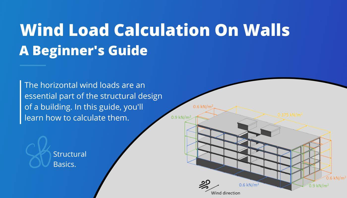
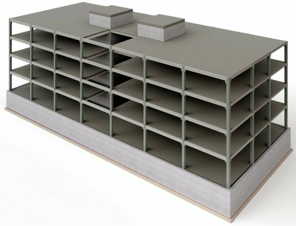
This time, we’ll calculate the wind loads on facade elements for a precast concrete office building.
Let’s get started. 🚀🚀
Process Of Calculating The Wind Loads On Walls
In order to calculate the wind load or wind pressure on external surfaces, we are going to do the following steps:
- Calculate the wind velocity pressure qp
- Define the outer geometry of the building
- Calculate the width of the Wind areas
- Find the external pressure coefficients
- Calculate the wind pressures/loads
Define geometry and parameters from wind velocity pressure
This is a quick summary of the values we calculated to get the wind velocity pressure.
| Fundamental value of basic wind velocity | vb.0 | 24 m/s |
| Orography factor | c0 | 1.0 |
| Turbulence factor | kl | 1.0 |
| Density of air | $\rho$ | 1.25 kg/m3 |
| Reference height of Terrain cat. II | z0.II | 0.05 m |
| Roughness Length (Terrain cat. III) | z0 | 0.3 m |
| Terrain factor | kr | 0.215 |
| Turbulance Intensity | Iv | 0.247 |
| Roughness factor | cr | 0.871 |
| Mean wind velocity | vm | 20.9 m/s |
| Peak velocity pressure | qp | 0.746 kN/m2 |
Wind pressure on surfaces
In general, distinguishes Eurocode between wind pressure on external and internal surfaces. This article is focusing on the wind pressure on external surfaces.
Wind pressure on external surfaces we
The formula to calculate the wind pressure on external surfaces is
$$w_{e} = q_{p} \cdot c_{pe}$$
Where
| qp | is the peak velocity pressure and |
| cpe | is the external pressure coefficient |
The coefficient cpe has 2 different values depending on the wind loaded area.
There is a value for a surface area of 1 m2 and 10 m2. These to values can also be written as
| cpe.1 | for the external pressure coefficient for an area of 1 m2 and |
| cpe.10 | for the external pressure coefficient for an area of 10 m2 |
You are now probably wondering: “When do we ever design a load bearing element where only 1 m2 is loaded?🤔”
Well, you are right, that is almost never the case for beams and slabs. But for smaller elements like cladding elements of the facade or fixings, cpe.1 comes into play (EN 1991-1-4 7.2.1 Note 1).
As a short summary:
- cpe.10 is usually used for the overall load bearing structure
- cpe.1 is used for small elements within elements, such as cladding
Enough explanation, let’s have a look at the values of the coefficients.
EN 1991-1-4 Table 7.1 gives recommendations for cpe.10 and cpe.1. This means that you have to double-check with your National annex because those values might be defined differently there.
Table 7.1 gives values for 5 different areas A, B, C, D and E of our building.
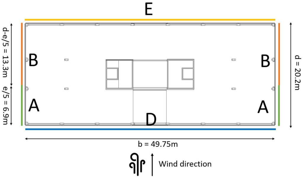
Those areas depend on where the wind comes from and can be seen in EN 1991-1-4 Table 7.1. For our office building, we can define the areas as
Wind from Front
| Width of building | b | 49.75 m |
| Length of building | d | 20.2 m |
| Height of building | h | 17.1m |
From those dimensions we can define e which determines the width of Areas A and B according to EN 1991-1-4 Figure 7.5.
$$e = min(b, 2h)$$
$$e = min(49.75m, 2 \cdot 17.1m=34.4m) = 34.4m$$
For the case of e > d which is true for us, the width of Area A is defined as:
$$e/5 = 6.9m$$
So let’s visualize all of those numbers. 🖼️🖼️
We did not include the walls on the rooftop in the following picture due to better visualization. We also need to take them into account.
💡
You might be asking why the Areas are not applied to the bottom walls. Those are basement walls and surrounded by soil. Therefore, wind is not reaching them.
Okay, now let’s go back to the formula for the wind pressure for external surfaces and derive the values. The peak velocity pressure was calculated in the last article as
$$q_{p} = 0.746 \frac{kN}{m^2}$$
The external pressure coefficients for rectangular buildings can be taken from EN 1991-1-4:2005 Table 7.1.
For a height to width ratio h/d = 17.1m/20.2m = 0.85 which is < 1 and > 0.25 we get the following coefficients.
| Area | cpe.10 | cpe.1 |
| Area A | -1.2 | -1.4 |
| Area B | -0.8 | -1.1 |
| Area D | 0.8 | 1.0 |
| Area E | -0.5 | -0.5 |
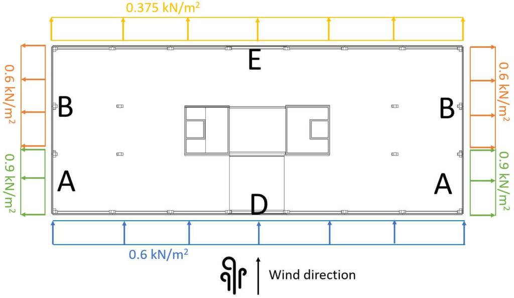
Based on our coefficients, we can now calculate the Wind pressure on external surfaces.
| Area | we.10 | we.1 |
| A | $-1.2 \cdot 0.75 \frac{kN}{m^2} = -0.9 \frac{kN}{m^2} $ | $-1.4 \cdot 0.75 \frac{kN}{m^2} = -1.05 \frac{kN}{m^2}$ |
| B | $-0.8 \cdot 0.75 \frac{kN}{m^2} = -0.6 \frac{kN}{m^2} $ | $-1.1 \cdot 0.75 \frac{kN}{m^2} = -0.825 \frac{kN}{m^2}$ |
| D | $0.8 \cdot 0.75 \frac{kN}{m^2} = 0.6 \frac{kN}{m^2} $ | $1.0 \cdot 0.75 \frac{kN}{m^2} = -0.75 \frac{kN}{m^2}$ |
| E | $-0.5 \cdot 0.75 \frac{kN}{m^2} = -0.375 \frac{kN}{m^2} $ | $-1.1 \cdot 0.75 \frac{kN}{m^2} = -0.375 \frac{kN}{m^2}$ |
When you calculate the wind loads the first time ever, it might be very confusing in which direction you have to apply the loads.
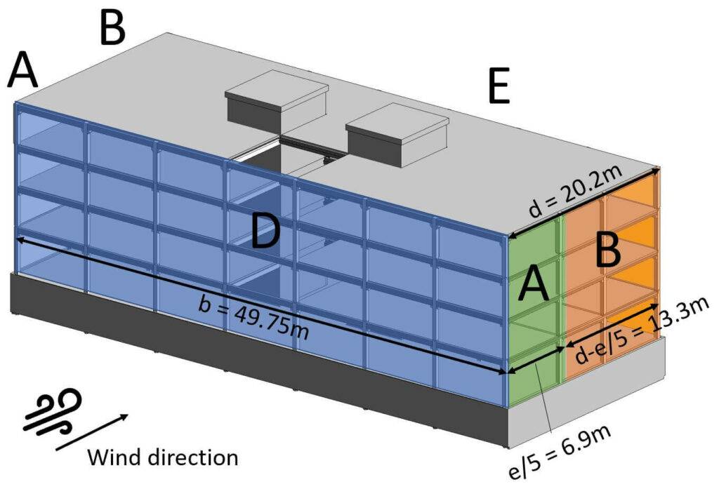
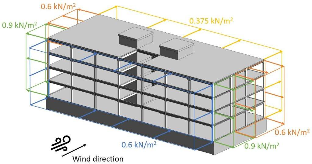
So let’s apply the wind loads (for 10 m2) on our building.
To better understand it, we have a look at a 3D picture.
Now we also have to do the same for the case that wind comes from the side.
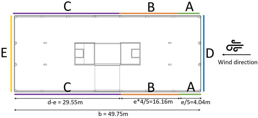
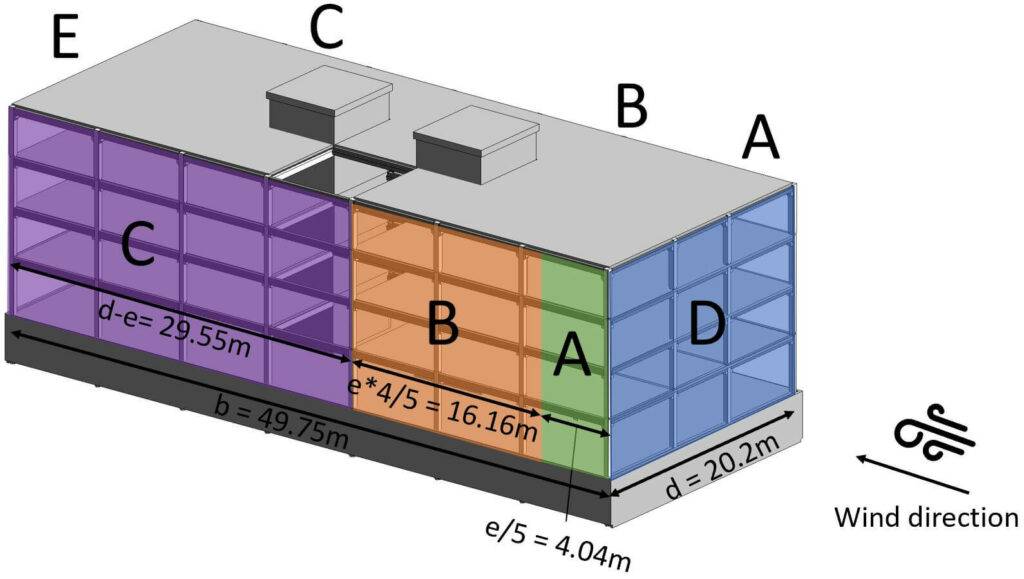
Wind from Side
In the scenario that wind comes from the side, we have to define the Area widths again. We have to redefine the geometry parameters.
| Width of building | b | 20.2 m |
| Length of building | d | 49.75 m |
| Height of building | h | 17.1m |
From those dimensions we can define $e$ according to EN 1991-1-4 Figure 7.5
$$e = min(b, 2h)$$
$$e = min(20.2m, 2 \cdot 17.1m=34.4m) = 20.2m$$
For the case of e < d which is true for us, the width of Area A is defined as
$$e/5 = 4.04m$$
The Area B is calculated as
$$e \cdot4/5 = 16.16m$$
The Area C is therefore the rest of d and calculated as
$$d – e = 49.75m – 20.2m = 29.55m$$
So let’s visualize all of those numbers. 🖼️🖼️
For a height to width ratio h/d = 17.1m/49.75m = 0.34 which is < 1 and > 0.25 we get the following coefficients we get the same coefficients for A, B, D and E as for Wind from Front, but additionally we get now a value for C (EN 1991-1-4:2005 Table 7.1).
| Area | cpe.10 | cpe.1 |
| A | -1.2 | -1.4 |
| B | -0.8 | -1.1 |
| C | -0.5 | -0.5 |
| D | 0.8 | 1.0 |
| E | -0.5 | -0.5 |
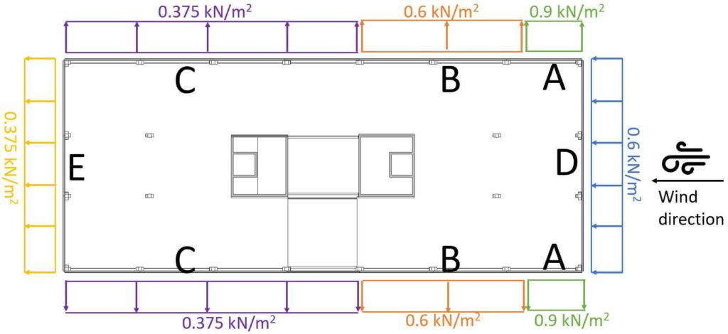
Based on our coefficients, we can now calculate the Wind pressure on external surfaces.
| Area | we.10 | we.1 |
| A | $-1.2 \cdot 0.75 \frac{kN}{m^2} = -0.9 \frac{kN}{m^2} $ | $-1.4 \cdot 0.75 \frac{kN}{m^2} = -1.05 \frac{kN}{m^2}$ |
| B | $-0.8 \cdot 0.75 \frac{kN}{m^2} = -0.6 \frac{kN}{m^2} $ | $-1.1 \cdot 0.75 \frac{kN}{m^2} = -0.825 \frac{kN}{m^2}$ |
| C | $-0.5 \cdot 0.75 \frac{kN}{m^2} = -0.375 \frac{kN}{m^2} $ | $-0.5 \cdot 0.75 \frac{kN}{m^2} = -0.375 \frac{kN}{m^2}$ |
| D | $0.8 \cdot 0.75 \frac{kN}{m^2} = 0.6 \frac{kN}{m^2} $ | $1.0 \cdot 0.75 \frac{kN}{m^2} = -0.75 \frac{kN}{m^2}$ |
| E | $-0.5 \cdot 0.75 \frac{kN}{m^2} = -0.375 \frac{kN}{m^2} $ | $-1.1 \cdot 0.75 \frac{kN}{m^2} = -0.375 \frac{kN}{m^2}$ |
Those wind area loads we can now visualize in a floor plan.
Reduction of Wind force on Areas D and E
According to EN 1991-1-4 7.2.2 (3) the wind loads can be reduced in the direction of the wind (Areas D and E) if they meet the following criteria:
$$h/d <1 $$
Wind from Front
$$h/d = 17.1m/20.2m = 0.85 < 1$$
The criteria are met, and the forces in Areas D and E can be reduced by the factor 0.85.
| Area | we.10 | we.1 |
| D | $0.85 \cdot 0.6 \frac{kN}{m^2} = 0.51 \frac{kN}{m^2} $ | $0.85 \cdot 0.75 \frac{kN}{m^2} = 0.64 \frac{kN}{m^2}$ |
| E | $0.85 \cdot (-0.375 \frac{kN}{m^2}) = -0.32 \frac{kN}{m^2} $ | $0.85 \cdot (-0.375 \frac{kN}{m^2}) = -0.32 \frac{kN}{m^2}$ |
Wind from Side
$$h/d = 17.1m/49.75m = 0.34 < 1$$
The criteria are met, and the forces in Areas D and E can be reduced by the factor 0.85.
| Area | we.10 | we.1 |
| D | $0.85 \cdot 0.6 \frac{kN}{m^2} = 0.51 \frac{kN}{m^2} $ | $0.85 \cdot 0.75 \frac{kN}{m^2} = 0.64 \frac{kN}{m^2}$ |
| E | $0.85 \cdot (-0.375 \frac{kN}{m^2}) = -0.32 \frac{kN}{m^2} $ | $0.85 \cdot (-0.375 \frac{kN}{m^2}) = -0.32 \frac{kN}{m^2}$ |
Conclusion
The wind loads on buildings must always be calculated for 2 directions. ⬇️➡️ The wind loads have different values for the different wall areas A, B, C, D and E, which are calculated with the pressure coefficients and the peak velocity pressure.
In addition, the wind load must also be calculated for the roof. We have explained this in detail in the following articles:
If you don’t want to miss any new structural design tutorials, then subscribe to our free weekly newsletter.
Or subscribe to my YouTube channel for regular updates.
Let’s design better structures together,
Laurin.
Wind Loads On Walls FAQ
The wind loads on walls are calculated according to Eurocode EN 1991-1-4.
The wind loads are important because they affect the stability of buildings and other structures. Wind loads can lead to structural damage, such as cracks in concrete walls, and even to the collapse of a structure.
![Uniformly Distributed Load [All YOU Need To Know]](https://www.structuralbasics.com/wp-content/uploads/2023/04/Uniformly-distributed-loads-768x439.jpg)
![Vertical Load Transfer In Structural Engineering [2026]](https://www.structuralbasics.com/wp-content/uploads/2024/09/Vertical-load-transfer-1-768x439.jpg)