Wind Loads On A Pitched Roof {A Structural Guide}
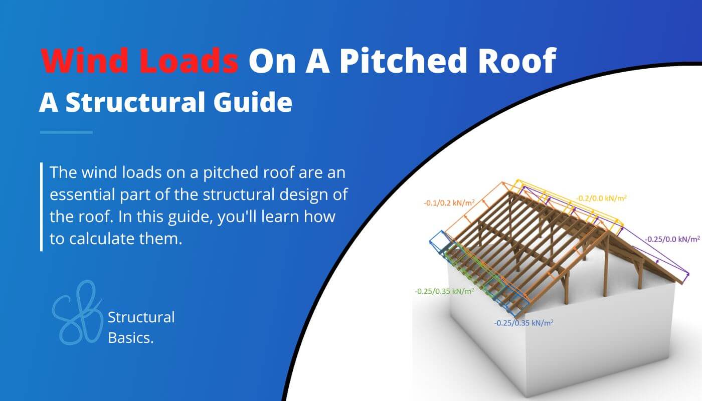
Wind loads on roofs need to be considered in the structural design of every building.
In this article, I show you how I as a structural engineer calculate the wind loads on pitched roofs according to EN 1991-1-4.
Before getting into it. If you want to learn everything you need to know about other loads like the snow load, wind load, dead load, live load or the imperfection load, then I invite you to join my free 8-day email course about loads.
This article builds up on the peak velocity pressure, which we calculated in a previous article for a precast office building.
We don’t repeat the calculation in this article, but define a value qp for it.
Just keep in mind that the values differ due to different parameters such as location and geometry.
Let’s get started.
Step-By-Step Process Of Calculating The Wind Loads On Pitched Roofs
In order to calculate the wind load or wind pressure on external surfaces of a pitched roof, we are going to do the following steps:
1. Calculate the wind velocity pressure qp
2. Define the outer geometry of the building
3. Calculate the width of the Wind areas
4. Find the external pressure coefficients
5. Calculate the wind pressures/loads
Example Building
We’ll use the following example building with a rafter roof to show step-by-step how to calculate the wind load on a pitched roof.

Geometry and Parameters From Wind Velocity Pressure
This is a quick summary of the values we calculate to get the wind velocity pressure. As already explained earlier, check out this article, if you want to learn how to calculate these parameters.
| Height of the building above ground | h | 6.0 m |
| Fundamental value of basic wind velocity | vb.0 | 24 m/s |
| Orography factor | c0 | 1.0 |
| Turbulence factor | kl | 1.0 |
| Density of air | $\rho$ | 1.25 kg/m3 |
| Reference height of terrain cat. II | z0.II | 0.05 m |
| Roughness Length (Terrain cat. III) | z0 | 0.3 m |
| Terrain factor | kr | 0.215 |
| Turbulence Intensity | Iv | 0.334 |
| Roughness factor | cr | 0.65 |
| Mean wind velocity | vm | 15.5 m/s |
| Peak velocity pressure | qp | 0.5 kN/m2 |
Wind Pressure on Roof Surfaces
Eurocode (EN 1991-1-4:2005) distinguishes in general between wind pressure on external and internal surfaces. This article is focusing on the wind pressure on external surfaces.
Wind pressure on external pitched roof surfaces we
Now we have written the exact same words and formulas already in the articles about the wind load of the flat roof and walls, but isn’t it good to repeat things, so they stick better with us? 🤔
Anyway, the formula (EN 1991-1-4:2005 (5.1)) to calculate the wind pressure on external surfaces is:
$$w_{e} = q_{p} \cdot c_{pe}$$
Where
| qp | is the peak velocity pressure and |
| cpe | is the external pressure coefficient |
The coefficient cpe has 2 different values depending on the wind loaded area. There is a value for a surface area of 1 m2 and 10 m2. These two values can also be written as
| cpe.1 | for the external pressure coefficient for an area of 1 m2 and |
| cpe.10 | for the external pressure coefficient for an area of 10 m2 |
Now, we already explained it a bit more detailed here. If you want to a more detailed explanation then either go to the article or read up in EN 1991-1-4:2005 7.2.
EN 1991-1-4 Table 7.3a and Table 7.3b give recommendations for cpe.10 and cpe.1.
❗This means that you have to double-check with your National annex because those values might be defined differently there❗
Tables 7.3a and 7.3b give values for 4 different areas F, G, H and I of our roof. Those areas depend on where the wind comes from and the shape of the roof.
Eurocode differentiates between mono- and duo pitched roofs.
What are mono- and duopitched roofs?
A mono pitched roof has basically only “one slope”. So no change in slope.

The duo pitch roof has basically “two slopes” which change at the highest point of the roof.

For “our” duo pitched roof, we can define the areas for both wind directions – Wind from the front and from the side.
Wind directions
We will be talking about wind from front and side in this article. The following picture emphasizes what we mean by front and side.

Wind from Front
For the case that the wind blows from the front direction, we can define some geometric dimensions of the building according to EN 1991-1-4:2005
| Width of building | b | 13.0 m |
| Length of building | – | 9.0 m |
| Height of building | h | 6.0 m |
From those dimensions we can define e which determines the widths and depths of Areas F, G, H, J and I according to EN 1991-1-4:2005 Figure 7.8.
$$e = min(b, 2h)$$
$$e = min(13.0m, 2 \cdot 6.0m=12.0m) = 12.0m$$
From e we get the dimensions of the areas according to EN 1991-1-4:2005 Figure 7.8.
| Area | Width | Depth |
| F | e/4 = 3.0m | e/10 = 1.2m |
| G | b-e/2 = 7.0m | e/10 = 1.2m |
| H | b = 13.0m | Ridge depth – e/10 = 3.3m |
| J | b = 13.0m | e/10 = 1.2m |
| I | b = 13.0m | Ridge depth – e/10 = 3.3m |
So many numbers – I know. Let’s visualize them.


Okay, now let’s go back to the formula for the wind pressure for external surfaces and derive the values. The peak velocity pressure was calculated as:
$$q_{p} = 0.5 \frac{kN}{m^2}$$
The external pressure coefficients for duopitch roofs with wind from front (direction angle $\Theta$) can be taken from EN 1991-1-4:2005 Table 7.4a.
For a roof slope angle of 29° $\approx$ 30° we get
| Area | cpe.10 | cpe.1 |
| Area F | -0.5/0.7 | -1.5/0.7 |
| Area G | -0.5/0.7 | -1.5/0.7 |
| Area H | -0.2/0.4 | -0.2/0.4 |
| Area I | -0.4/0 | -0.4/0 |
| Area J | -0.5/0 | -0.5/0 |
💡
Don’t be confused by the + and – of the coefficients of Area I. EN 1991-1-4:2005 Table 7.4a Note 1 says that due to rapid change wind, both positive and negative values are given. Therefore, 4 cases need to be considered in total – the smallest and largest coefficients of areas F, G and H with the smallest or largest coefficients of areas I and J.
Based on our coefficients, we can now calculate the wind pressure on external surfaces.
| Area | we.10 | we.1 |
| Area F | $-0.5(/0.7) \cdot 0.5 \frac{kN}{m^2} = -0.25(/0.35) \frac{kN}{m^2} $ | $-1.5(/0.7) \cdot 0.5 \frac{kN}{m^2} = -0.75(/0.35) \frac{kN}{m^2}$ |
| Area G | $-0.5(/0.7) \cdot 0.5 \frac{kN}{m^2} = -0.25(/0.35) \frac{kN}{m^2} $ | $-1.5(/0.7) \cdot 0.5 \frac{kN}{m^2} = -0.75(/0.35) \frac{kN}{m^2}$ |
| Area H | $-0.2(/0.4) \cdot 0.5 \frac{kN}{m^2} = -0.1(/0.2) \frac{kN}{m^2} $ | $-0.2(/0.4) \cdot 0.5 \frac{kN}{m^2} = -0.1(/0.2) \frac{kN}{m^2}$ |
| Area I | $-0.4(/0.0) \cdot 0.5 \frac{kN}{m^2} = -0.2(/0.0) \frac{kN}{m^2} $ | $-0.4(/0.0) \cdot 0.5 \frac{kN}{m^2} = -0.2(/0.0) \frac{kN}{m^2}$ |
| Area J | $-0.5(/0.0) \cdot 0.5 \frac{kN}{m^2} = -0.25(/0.0) \frac{kN}{m^2} $ | $-0.5(/0.0) \cdot 0.5 \frac{kN}{m^2} = -0.25(/0.0) \frac{kN}{m^2}$ |
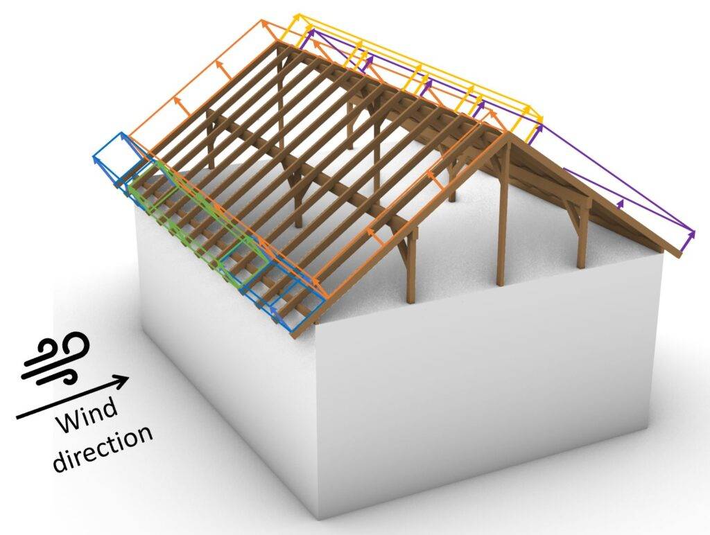
When you calculate the wind loads the first time ever, it might be very confusing in which direction you have to apply the loads. So let’s apply the wind loads with the cpe.10 coefficient (for 10 m2) on our building.

❗
The minus (-) values stand for suction – wind force away from the surfaces. Therefore, the first value of the wind load is represented by the area load. For the cases of positive (+) values, the direction of the loads – the direction of the arrows – has to change.
Now we also have to do the same for the case that wind comes from the side.
Wind from Side
In the scenario that wind comes from the side, we have to define the area widths again. We have to redefine the geometry parameters.
| Width of building | b | 9.0 m |
| Length of building | d | 13.0m |
| Height of building | h | 6.0m |
From those dimensions we can define e which determines the widths and depths of Areas F, G, H and I according to EN 1991-1-4:2005 Figure 7.8.
$$e = min(b, 2h)$$
$$e = min(9.0m, 2 \cdot 6.0m=12.0m) = 9.0m$$
From e we get the dimensions of the areas according to EN 1991-1-4:2005 Figure 7.8.
| Area | Width | Depth |
| F | e/4 = 2.25m | e/10 = 0.9m |
| G | b-e/2 = 4.5m | e/10 = 0.9m |
| H | b = 9.0m | e/2 – e/10 = 3.6m |
| I | b = 9.0m | d-e/2 = 8.5m |
As we all know, a picture tells more than a thousand words – so let’s visualize all of those numbers.

The external pressure coefficients for duo pitched roofs with the wind direction of $\Theta$ = 90° and a roof slope angle of 29° $\approx$ 30° can be taken from EN 1991-1-4:2005 Table 7.4b
| Area | cpe.10 | cpe.1 |
| Area F | -1.1 | -1.5 |
| Area G | -1.4 | -2.0 |
| Area H | -0.8 | -1.2 |
| Area I | -0.5 | -0.5 |
Based on our coefficients, we can now calculate the Wind pressure on external surfaces.
| Area | we.10 | we.1 |
| Area F | $-1.1 \cdot 0.5 \frac{kN}{m^2} = -0.55 \frac{kN}{m^2} $ | $-1.5 \cdot 0.5 \frac{kN}{m^2} = -0.75 \frac{kN}{m^2}$ |
| Area G | $-1.4 \cdot 0.5 \frac{kN}{m^2} = -0.7 \frac{kN}{m^2} $ | $-2.0 \cdot 0.5 \frac{kN}{m^2} = -1.0 \frac{kN}{m^2}$ |
| Area H | $-0.8 \cdot 0.5 \frac{kN}{m^2} = -0.4 \frac{kN}{m^2} $ | $-1.2 \cdot 0.5 \frac{kN}{m^2} = -0.6 \frac{kN}{m^2}$ |
| Area I | $-0.5 \cdot 0.5 \frac{kN}{m^2} = -0.25 \frac{kN}{m^2} $ | $-0.5 \cdot 0.5 \frac{kN}{m^2} = -0.25 \frac{kN}{m^2}$ |
Those wind area loads we can now visualize.

Conclusion
For a building of 6.0 m height, located in Copenhagen, Denmark, the wind load of a pitched roof is calculated for 2 directions and for 5 different wind areas as we learned in this article.
If you want to learn how to calculate the wind load on walls and pitched roofs, then check out the articles:
- Wind load calculation on flat roofs
- Calculation of the peak velocity pressure
- Wind load calculation on walls
If you don’t want to miss any new structural design tutorials, then subscribe to our free weekly newsletter.
Or subscribe to my YouTube channel for regular updates.
Let’s design better structures together,
Laurin.

![Earth Pressure Calculation On Underground Structures [2026]](https://www.structuralbasics.com/wp-content/uploads/2024/07/Earth-pressure-calculation-768x439.jpg)
![Wind Load Calculation On Walls [A Beginner’s Guide]](https://www.structuralbasics.com/wp-content/uploads/2022/02/Wind-loads-on-walls-768x439.jpg)
![How To Calculate The Wind Loads Of A Flat Roof [2026]](https://www.structuralbasics.com/wp-content/uploads/2022/02/Wind-loads-on-flat-roofs-768x439.jpg)