Wind load calculation on an arched roof (Example)
After we have already covered the wind velocity, wind loads on walls, flat roofs and pitched roofs, this time we calculate the wind load for – a structure most structural engineers probably do not work with everyday🤔 – arched roofs or also called circular cylindrical roofs.
In today’s post we’ll show you exactly how to calculate the wind load for an arched roof with an example according to EN 1991-1-4:2005 7.2.8.
Let’s dive right into it.
🙋♂️ What is an arched structure?
An arched structure – or also called an arch – is categorized as a structure mainly acting in compression due to its geometry. Arches are used in bridges to span over rivers, in older buildings to span over window openings and in aqueducts made by the Romans to name just a few use cases.
There are different forms and static systems of arches.
Forms of arches
In general, it can be differentiated between the following arch forms
- Pointed arches
- Circular or rounded arches
- Parabolic arches
Static systems of arches
Hingeless arch
The hingeless consists of 2 fixed supports and no hinge anywhere in the structure.
One-hinged arch
The one-hinged arch is characterized by its hinge in the middle between the two supports. Both supports are fixed.
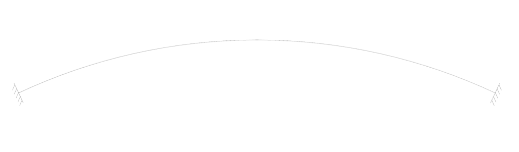
Two-hinged arch
The two-hinged arch is like the hingeless arch but instead of having fixed supports, it has two pinned supports.
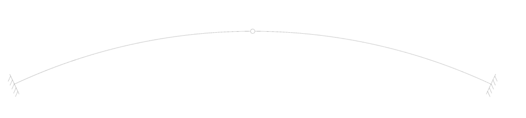
Three-hinged arch
The three-hinged arch consists of two pinned support and additionally a hinge at the crown.
This static system is statically determinate, and the forces can therefore easily be calculated by hand.
Example arch
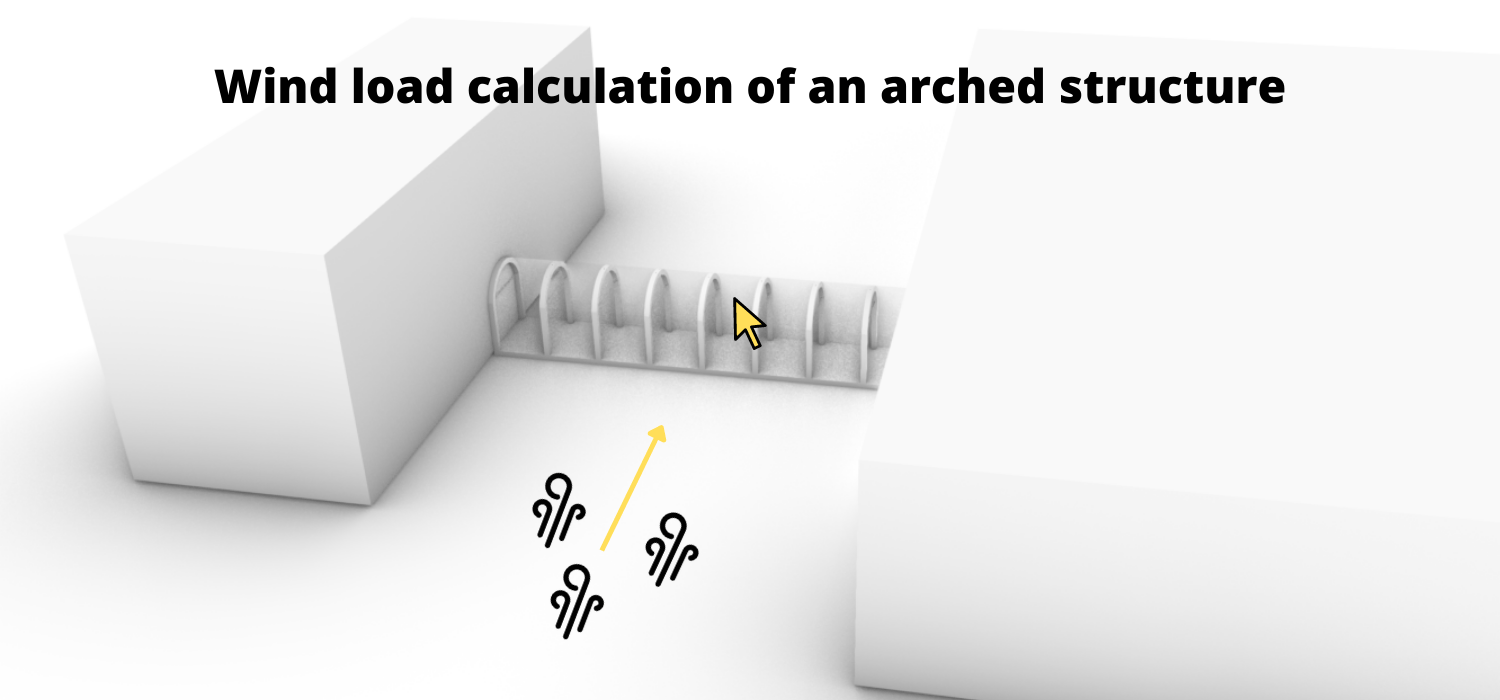
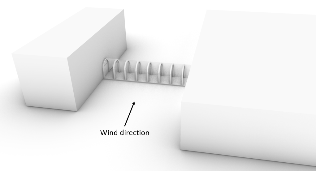
The calculations are based on an arched structure, which can be seen in the picture below.
This structure presents a closed-off walkway between two buildings.
The wind loads are applied on the glass spanning between the arches.
Okay, now we have driven away from the actual topic – calculating the wind force of an arched structure – but I think knowing the basics about arches is helpful and interesting, isn’t it? 🤔
💡Before we start diving into the wind load calculation – just a quick information ..
The calculation of the wind load is split up in multiple articles due to the fact that the wind load depends on much more parameters that need to be derived than for example the snow or live load.
This article builds up on the peak velocity pressure, which we calculated in a previous article for a precast office building.
We are not repeating the calculation in this article, but define a value $q_p$ for it.
The calculation steps of the peak velocity pressure for arched structures is the same as for the precast concrete building.
Just keep in mind that the values differ due to different parameters such as location and geometry.
🏠 Geometry and parameters from wind velocity pressure
This is a quick summary of the values we calculate to get the wind velocity pressure.
| Height of the building above ground | $h$ | $4.5m$ |
| Fundamental value of basic wind velocity | $v_{b.0}$ | $24 \frac{m}{s} $ |
| Orography factor | $c_{0} $ | $1.0 $ |
| Turbulence factor | $k_{l} $ | $1.0 $ |
| Density of air | $\rho$ | $1.25 \frac{kg}{m^3} $ |
| Reference height of Terrain cat. II | $z_{0.II}$ | $0.05 m$ |
| Roughness Length (Terrain cat. III) | $z_{0}$ | $0.3 m$ |
| Terrain factor | $k_{r}$ | $0.215$ |
| Turbulance Intensity | $I_{v}$ | $0.369$ |
| Roughness factor | $c_{r}$ | $0.583$ |
| Mean wind velocity | $v_{m}$ | $14.0 \frac{m}{s} $ |
| Peak velocity pressure | $q_{p}$ | $0.439 \frac{kN}{m^2}$ |
📐 Calculation of the dimensions of the wind areas – arched structure
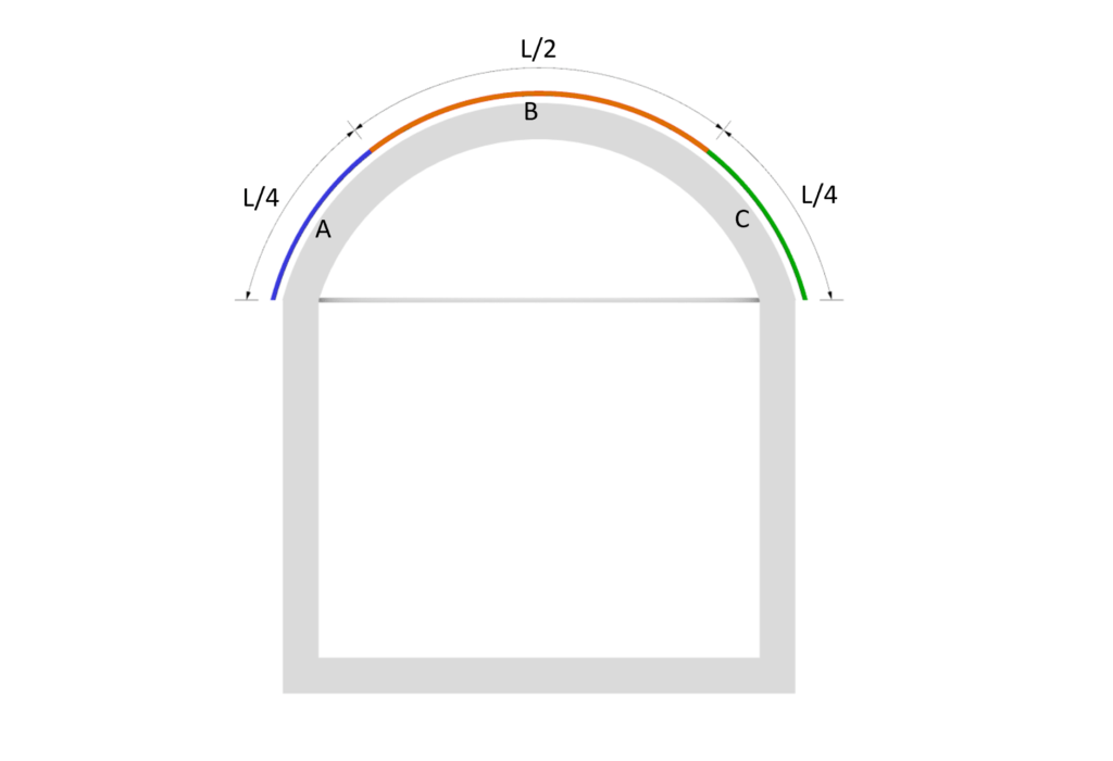
The wind areas for the circular cylindrical roof are taken from EN 1991-1-4:2005 Figure 7.11.
The wind areas are divided into Area A, B and C, where Area A takes up 1/4 of the arch surface starting from the wind direction.
Area B equals 1/2 of the arch length, starting from the endpoint of Area A.
Area C takes up the last 1/4 of the arch surface area.
All this is due to wind coming towards area A. If the wind direction was set to be towards Area C then Areas A and C would also change “position”.
The wind areas are visualized in the following pictures.
The 2D section view might emphasize the areas more accurate.
💨 Wind pressure on arch surfaces
Eurocode (EN 1991-1-4:2005) distinguishes in general between wind pressure on external and internal surfaces. This article is focusing on the wind pressure on external surfaces.
Wind pressure on external surfaces $w_{e}$
Now we have written the exact same words and formulas already in the articles about the wind load of the flat roof and walls, but isn’t it good to repeat things, so they stick better with us? 🤔
Anyway the formula (EN 1991-1-4:2005 (5.1)) to calculate the wind pressure on external surfaces is
$w_{e} = q_{p} * c_{pe}$
Where
| $q_{p}$ | is the peak velocity pressure and |
| $c_{pe}$ | is the external pressure coefficient |
The coefficient $c_{pe}$ has 2 different values depending on the wind loaded area.
There is a value for a surface area of 1 $ m^2$ and 10 $m^2$. These two values can also be written as
| $c_{pe.1}$ | for the external pressure coefficient for an area of 1 $ m^2$ and |
| $c_{pe.10}$ | for the external pressure coefficient for an area of 10 $ m^2$ |
Now, we already explained it a bit more detailed here. If you want to a more detailed explanation then either go to the article or read up in EN 1991-1-4:2005 7.2.
The $c_{pe.10}$ values can be extracted from the graph EN 1991-1-4:2005 EN 1991-1-4 Figure 7.11 for the f/h ratio. This ratio is calculated in the following.
Calculation of external wind pressure coefficients – arched roof
The following picture presents the values for f, h and d which are required for the calculation of pressure coefficients.
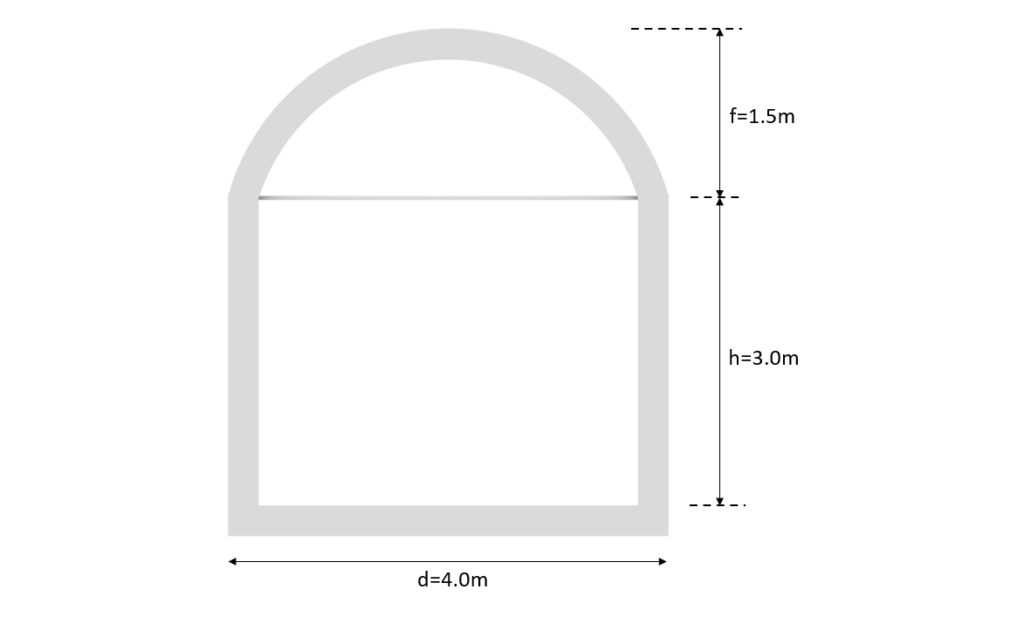
In order to extract the $c_{pe.10}$ value from EN 1991-1-4 the h/d and f/d ratios are required. With
h/d = 3m/4m = 0.75
and
f/d = 1.5m/4m = 0.375
the $c_{pe.10}$ values for Area A, B and C are derived as
| Area A | Area B | Area C | |
| $C_{pe.10}$ | 0.4-0.45 | -1.05 | -0.4 |
At this point, we should also mention that those external pressure coefficient are due to wind from one side of the arch.
↘️ Calculation of wind pressure/loads – arched roof
The formulation for the wind pressure is written as
$w_{k} = c_{pe.10} \cdot q_{p}$
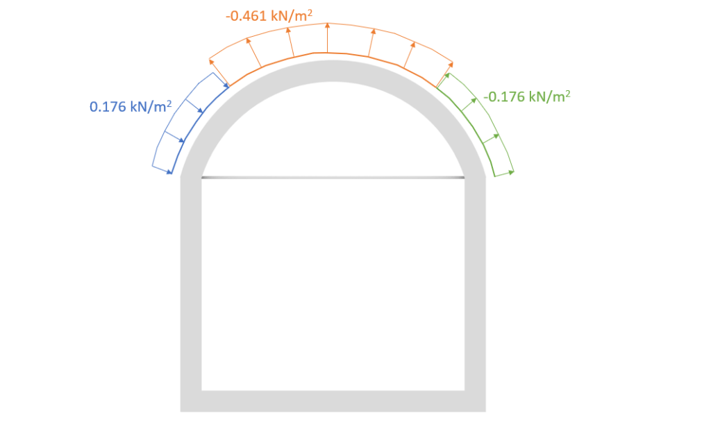
Based on the coefficients, the wind pressure on external surfaces can be calculated for Area A, B and C.
| Area | $w_{e.10}$ |
| Area A | $0.4 * 0.439 \frac{kN}{m^2} = 0.176 \frac{kN}{m^2} $ |
| Area B | $-1.05 * 0.439 \frac{kN}{m^2} = -0.461 \frac{kN}{m^2} $ |
| Area C | $-0.4 * 0.439 \frac{kN}{m^2} = -0.176 \frac{kN}{m^2} $ |
When you calculate the wind loads the first time, it might be very confusing in which direction you have to apply the loads. So let’s apply the calculated wind loads on our structure.
Et Voilà, the characteristic wind loads on the arched structure is calculated. But..
Don’t forget to calculate the wind loads on the walls. We didn’t touch base on them in this tutorial but have already written an extensive article about it which you can read here.
Now, I’d like to hear from you: Have you ever calculated an arched structure? If so, which static system did you choose and what type of structure was it? Leave a comment below ✏️
![Types of Loads on Beams [Full Guide]](https://www.structuralbasics.com/wp-content/uploads/2022/11/Types-of-loads-on-beams-768x439.jpg)
![Wind Load Calculation On Walls [A Beginner’s Guide]](https://www.structuralbasics.com/wp-content/uploads/2022/02/Wind-loads-on-walls-768x439.jpg)
![Earth Pressure Calculation On Underground Structures [2026]](https://www.structuralbasics.com/wp-content/uploads/2024/07/Earth-pressure-calculation-768x439.jpg)