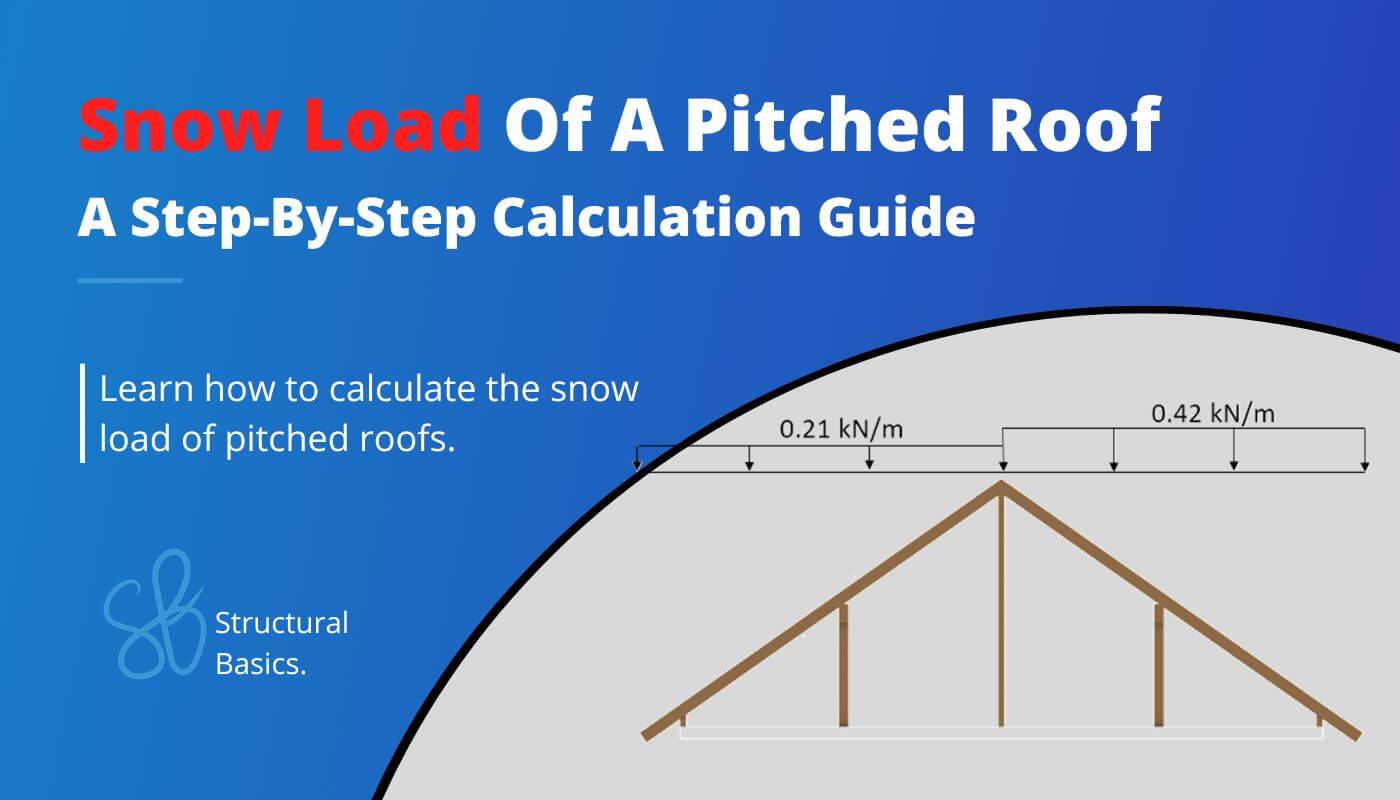
Snow Load Calculation Of Pitched Roofs {Step-By-Step Guide}
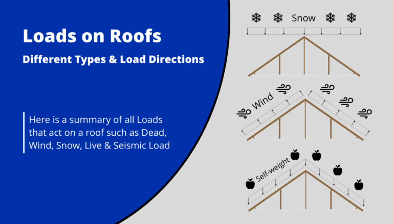
The snow load is an important part of any structural design. Every building needs to resist the snow load.
In this blog post, I show you, step-by-step, how the characteristic snow load of a pitched roof is calculated according to Eurocode.
Pitched roofs are for example purlin, rafter or collar beam roofs.
Before getting into it. If you want to learn everything you need to know about other loads like the snow load, wind load, dead load, live load or the imperfection load, then I invite you to join my free 8-day email course about loads.
But now let’s get started.
Step-By-Step Process Of Calculating The Snow Loads On Pitched Roofs
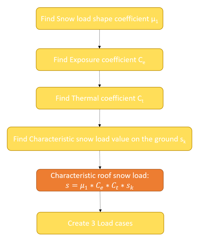
The calculation of the snow load for a pitched roof is a bit more complex than for a flat roof, but we only need to follow 6 steps. ⬇️⬇️
1. Find the snow load shape coefficient $\mu_{1}$
2. Exposure coefficient $C_{e}$
3. Thermal coefficient $C_{t}$
4. The characteristic snow load value on the ground $s_k$
5. Calculate the snow load value on the roof
6. Create 3 cases with different load considerations on the left and right pitch
Snow Load Formula
A persistent / transient design situation EN 1991-1-3 (5.1) is used to calculate the characteristic snow load:
$$s = \mu_{i} \cdot C_{e} \cdot C_{t} \cdot s_{k}$$
Where
- $\mu_{i}$ = the snow load shape coefficient
- Ce = the exposure coefficient
- Ct = the thermal coefficient and
- sk = the characteristic snow load value on the ground
Let’s have a closer look how we get those parameters.
Snow Load Shape Coefficient $\mu_{i}$
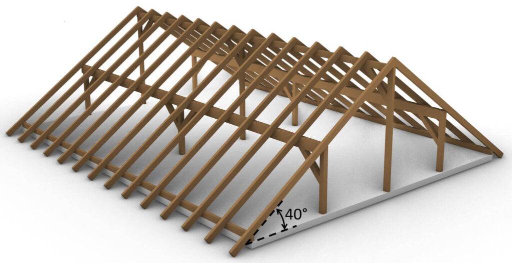
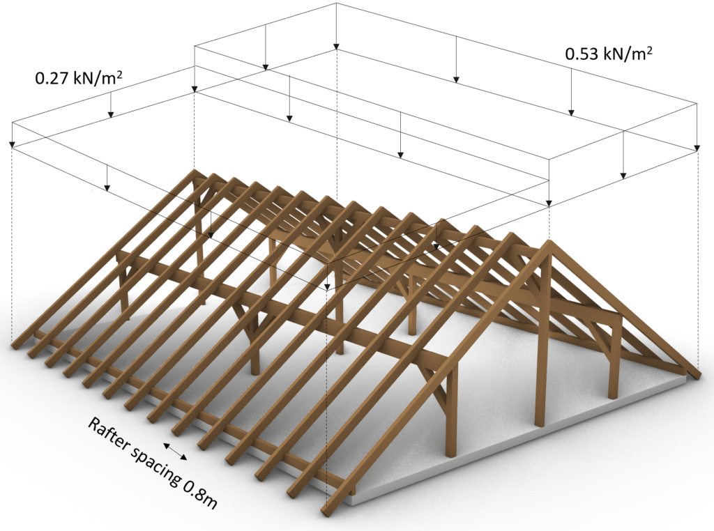
The purlin roof we are looking at in this example is a pitched roof.
When increasing the angle of the roof slope over 30°, the snow load shape coefficient $\mu_{1}$ can be decreased below 0.8 due to sliding of the snow off the roof.
The value for $\mu_{1}$ is given in EN 1991-1-3 Table 5.2. For $\alpha$ = 40 which means that the slope of the roof is 40°, we get:
$$\mu_{1} = 0.8 \cdot (60 – \alpha)/30$$
$$\mu_{1} = 0.8 \cdot (60 – 40)/30 = 0.53$$
A slope of 40° reduces $\mu_{1}$ therefore by $ \frac{0.533-0.8}{0.8} \cdot 100 = 33.4%$
Exposure coefficient Ce
EN 1991-1-3 5.2 (7) recommends Ce to be taken as 1.0. However, this value depends on the topography of the location.
EN 1991-1-3 Table 5.1 categorizes the topography in windswept, normal and sheltered with different values for Ce.
In this blog post, we assume a normal topography for our design. Therefore:
$$C_{e} = 1.0 $$
❗
Please double-check with your National annex because the $C_e$ values can be specified there for your country.
Thermal coefficient Ct
EN 1991-1-3 5.2 (8) defines Ct as 1.0.
However, this value can be reduced if the roof is covered by glass, which would lead to melting of the snow. In our case, we are not using any glass.
Therefore:
$$C_{t} = 1.0 $$
Characteristic snow load value on the ground sk
The characteristic snow load on the ground is found in the national annex of the country your roof is located in.
However, there is a great online tool which calculates the snow load according to location and national annex.
Click on the link, enter the location and the national annex.
If we do that for Copenhagen, Denmark, we get a value of
$$s_{k} = 1.0 \frac{kN}{m^2}$$
So now we finally have all 4 values required to calculate the characteristic snow load of a pitched roof (40° slope).
The snow load for this pitched roof located in Copenhagen, Denmark is calculated as:
$$s = \mu_{i} \cdot C_{e} \cdot C_{t} \cdot s_{k}$$
$$s = 0.53 \cdot 1.0 \cdot 1.0 \cdot 1.0 \frac{kN}{m^2} = 0.53 \frac{kN}{m^2}$$
This load is now applied vertically to the pitched roof.
Compared to the dead load the snow load is not following the slope of the rafter.
But because the roof is pitched, there are 3 different cases that we need to consider due to drifted load arrangements (EN 1991-1-3 5.3.3 (3) + (4)).
3 Snow Loading Cases On Pitched Roofs
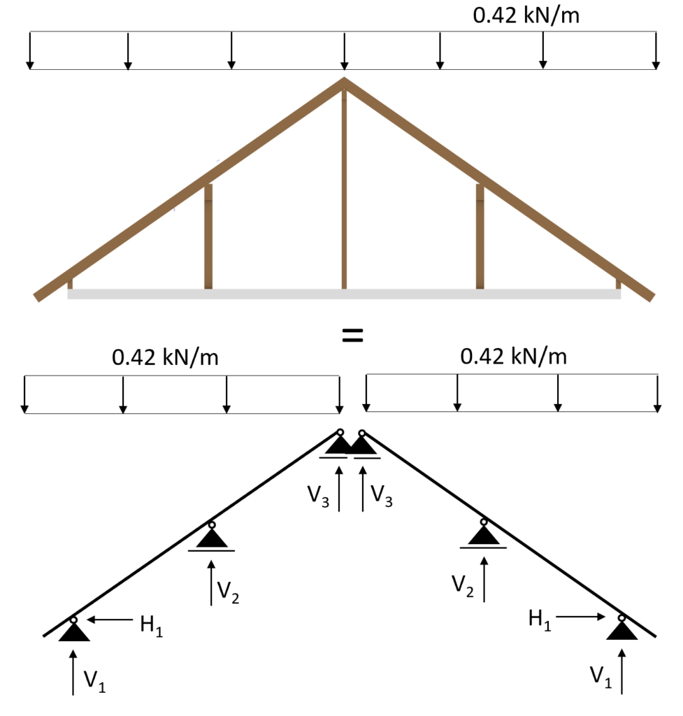
Case 1: s = 0.53 kN/m2 is applied on the whole area
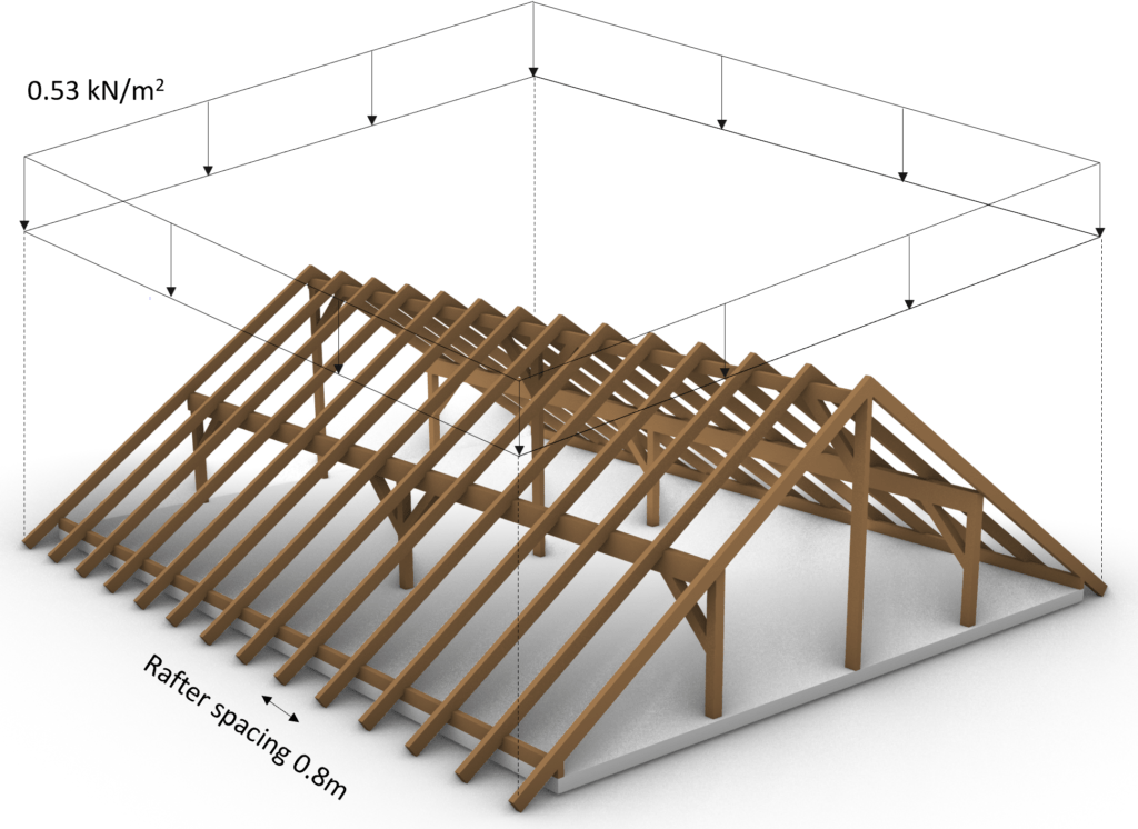
Transformed in a 2d statical system, we calculate the line load (kN/m) from the area load (kN/m2) by multiplying the area load with the spacing of the rafters = 0.8m.
$$s = 0.53 \frac{kN}{m^2} \cdot 0.8m = 0.42 \frac{kN}{m}$$
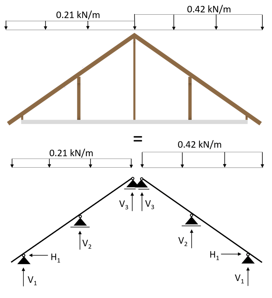
Case 2: s = 0.53 kN/m2 is applied on the left inclination and s/2 = 0.27 kN/m2 on the right inclination

Transformed in a 2d static system, we calculate s/2 as:
$$s = \frac{0.42}{2} \frac{kN}{m} = 0.21 \frac{kN}{m}$$
Case 3: s/2 = 0.27 kN/m2 is applied on the left inclination and s = 0.53 kN/m2 on the right inclination
Those 3 load cases need to be accounted for separately when doing the load combinations.
This means that every load combination which includes the snow load needs to be executed 3 times for the 3 different cases.
I know this is hard to understand in words, let’s look at an example.
Load Combinations With The Snow Load
We design and verify structural elements like timber beams and columns with design load. These design loads are the results of load combinations. If you want to learn more about load combinations, then read our article.
For now, we assume you know what load combinations are.
We are picking out LC8 from our load combination article from the ULS combinations.
| LC8 | $\gamma_{g} \cdot g_{k} + \gamma_{q} \cdot s_{k} $ |
LC8 needs to be executed 3 times, leading to:
| LC8-1 | $\gamma_{g} \cdot g_{k} + \gamma_{q} \cdot s_{k.case1} $ |
| LC8-2 | $\gamma_{g} \cdot g_{k} + \gamma_{q} \cdot s_{k.case2} $ |
| LC8-3 | $\gamma_{g} \cdot g_{k} + \gamma_{q} \cdot s_{k.case3} $ |
We are assuming the following values for the γ values and the dead load.
| $\gamma_{g}$ | 1.35 |
| $\gamma_{q}$ | 1.5 |
| $g_{k}$ | 0.86 kN/m |
This leads us to the following values of the 3 cases of LC8.
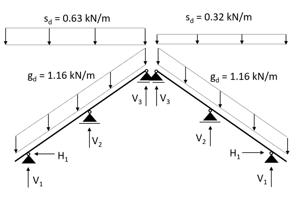
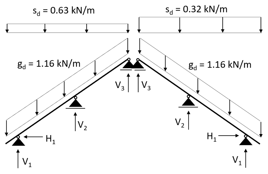
| LC8-1 | $1.35 \cdot 0.86 \frac{kN}{m} + 1.5 \cdot 0.42 \frac{kN}{m}$ |
| LC8-2 (left) | $1.35 \cdot 0.86 \frac{kN}{m} + 1.5 \cdot 0.42 \frac{kN}{m}$ |
| LC8-2 (right) | $1.35 \cdot 0.86 \frac{kN}{m} + 1.5 \cdot 0.21 \frac{kN}{m}$ |
| LC8-3 (left) | $1.35 \cdot 0.86 \frac{kN}{m} + 1.5 \cdot 0.21 \frac{kN}{m}$ |
| LC8-3 (right) | $1.35 \cdot 0.86 \frac{kN}{m} + 1.5 \cdot 0.42 \frac{kN}{m}$ |
💡
Maybe you have already asked yourself, “Why do we need to write LC8-2 and LC8-3? Aren’t they the same?” And yes, you are right. Due to the symmetry of our purlin roof, we only have to consider LC8-1 and LC8-2. However, in theory all 3 cases have to be considered. When the inclinations or the lengths of the two sides of the roof differ from each other, then all 3 cases have to be considered.
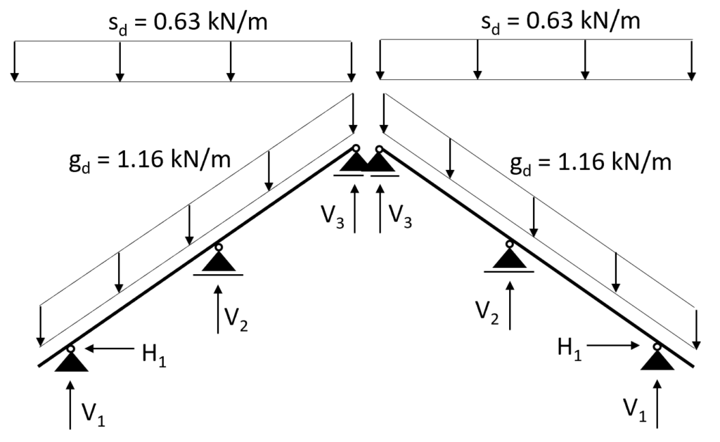
Now let’s apply the line loads to our static system.
Conclusion
You now learned how to calculate the snow load on pitched roofs according to Eurocode EN 1991-1-3.
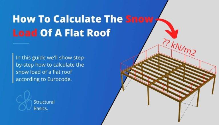
In case you want to learn how to calculate the snow load on flat roofs, then check out this article.
With this knowledge, you can now go on to the next step and apply the snow load (value from a load combination) and design a timber roof beam.
If you don’t want to miss any new structural design tutorials, then subscribe to our free weekly newsletter.
Or subscribe to my YouTube channel for regular updates.
Let’s design better structures together,
Laurin.

![How To Calculate The Wind Loads Of A Flat Roof [2026]](https://www.structuralbasics.com/wp-content/uploads/2022/02/Wind-loads-on-flat-roofs-768x439.jpg)
![Vertical Load Transfer In Structural Engineering [2026]](https://www.structuralbasics.com/wp-content/uploads/2024/09/Vertical-load-transfer-1-768x439.jpg)