Diaphragm Action – Horizontal Load Distribution Of RC Slabs
In this article, you’ll learn how diaphragm action works and how horizontal loads travel through reinforced concrete slabs to stabilizing elements such as shear walls and frames.
Now, let’s get into it.
How Does Diaphragm Action Work?
But First, we need to cover the 3 different types of diaphragms: rigid, flexible and semi-rigid diaphragms..
Rigid Diaphragms
When slabs are very stiff compared to the vertical stabilizing elements like shear walls or frames, then diaphragms are rigid. This means that the in-plane deformation of the slabs is very small compared to the horizontal deflection of the shear walls / frames. Reinforced concrete floors are in general rigid. In this tutorial, we’ll also use the rigid floor method later to distribute the loads to the stabilizing elements.
The rigid floor method assumes that the diaphragm is infinitely rigid, which means that the diaphragm can rotate and translate, but it can’t deflect.
Flexible Diaphragms
When the stabilizing elements of a building are quite stiff compared to the in-plane stiffness of the diaphragm, we can classify the slab as a flexible diaphragm. This means that the diaphragm has little influence on the distribution of the loads because it doesn’t have the capacity to redistribute the forces / loads from one stabilizing element to another.
Example of flexible diaphragms are metal roof sheets such as trapezoidal roof panels.
Semi-Rigid Diaphragms
A mix of flexible and rigid floors are semi-rigid diaphragms. This is the case when the in-plane deflections of the slab have an influence on the distribution of the horizontal loads to the stabilizing elements.
This requires advanced computer analysis like in a FE-program. The stiffness of the slab needs to be included in the analysis, and the diaphragm must be modelled as shell or plate elements.
The semi-rigid diaphragm method is the most accurate method, but it also requires more time and is more prone to errors.
In most cases, the rigid floor method is valid, as reinforced concrete slabs are very rigid.
Let’s check the rigid floor method out…
The Rigid Floor Method: The 8 Steps to Distribute Horizontal Loads on RC Slabs to Shear Walls
Before jumping into the rigid floor method we need to clarify how horizontal loads like wind loads are transformed from an area load on the facades to line loads on the slabs.
Basically the facades like masonry walls, reinforced concrete walls or facade elements distribute half of the load to the upper floor and half of the load to the lower floor acting as a simply supported beam.
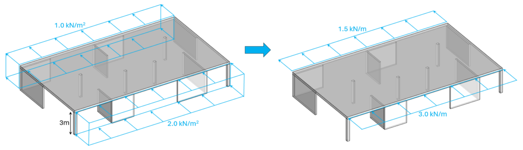
The reinforced concrete slabs act as diaphragms and distribute the line loads from the facades to the shear walls and frames.
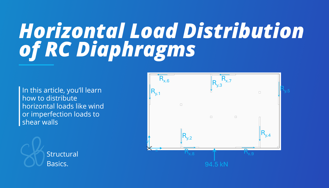
Here’s the example structure that we use in this email.
Step #1: Calculate the horizontal loads acting on the slab
First, we need to calculate the characteristic and design horizontal wind loads on the slabs. We won’t show how to calculate the loads in this newsletter, as we have covered that many times already. You can check out my YouTube video or my e-book to learn more:
In this article, we’ll use the following horizontal design line loads:
- Design line load (pressure) wd.p = 3 kN/m
- Design line load (suction) wd.s = 1.5 kN/m
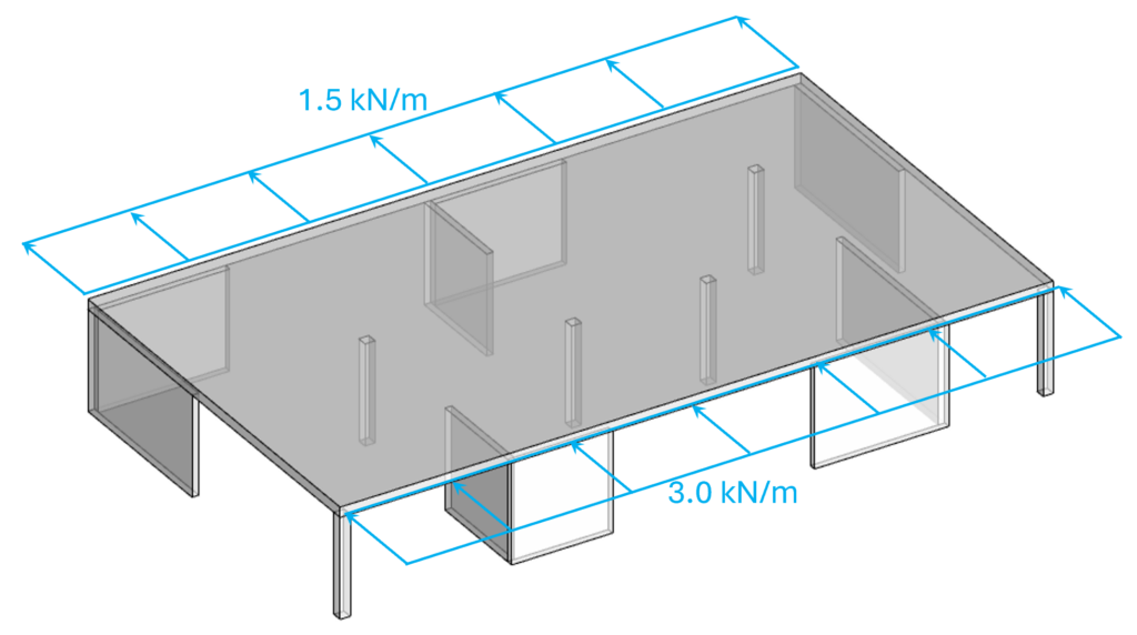
We didn’t apply the horizontal loads on the gable walls, because they act as suction and equal themselves out.
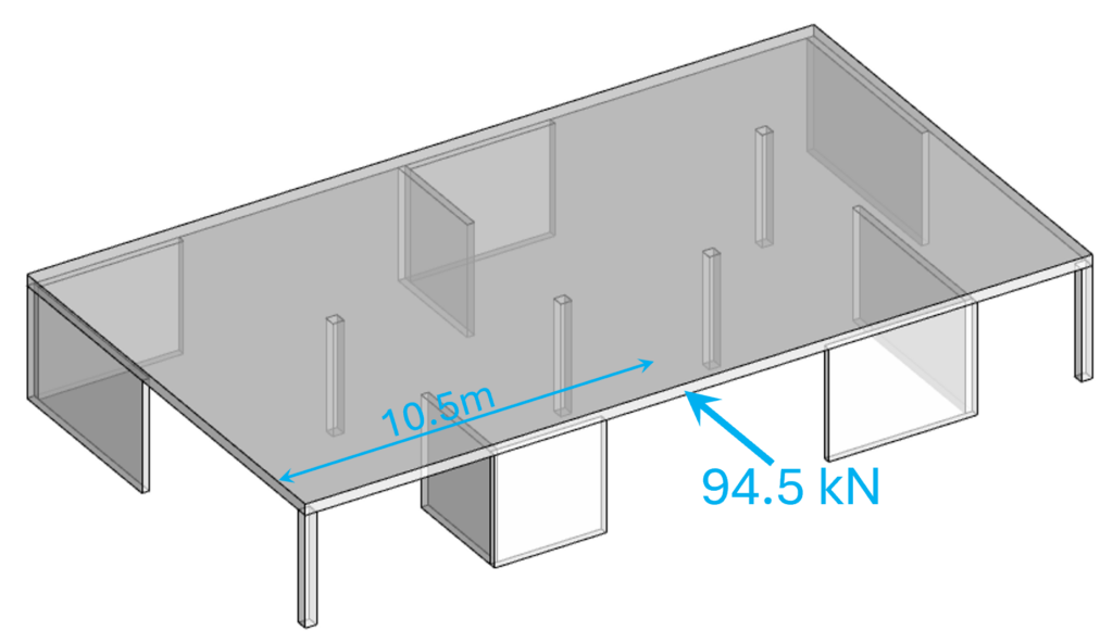
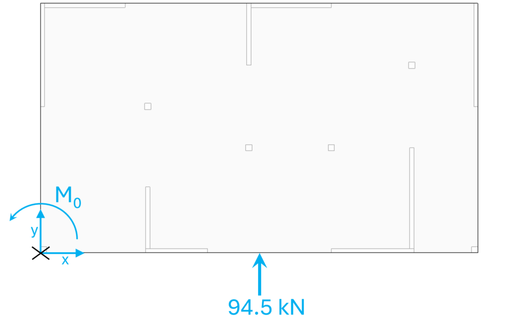
The resultant point load is:
Ry = (1.5 kN/m + 3.0 kN/m) ⋅ 21m = 94.5 kN
Step #2: Geometry of the slab and the walls
Here are the geometrical properties of the slab and the walls:
- Slab thickness: ts = 30cm
- Walls thickness: tw = 20cm
- Height of the walls: hw = 3.0m
From these parameters, we can calculate the moment of inertia of the walls.
Moment of inertia wall length l=3m
Iy.1 = ((3m)3 ⋅ tw)/12 = 0.45 m4
Moment of inertia wall length l=4m
Iy.2 = ((4m)3 ⋅ tw)/12 = 1.07 m4
Moment of inertia wall length l=5m
Iy.3 = ((5m)3 ⋅ tw)/12 = 2.08 m4
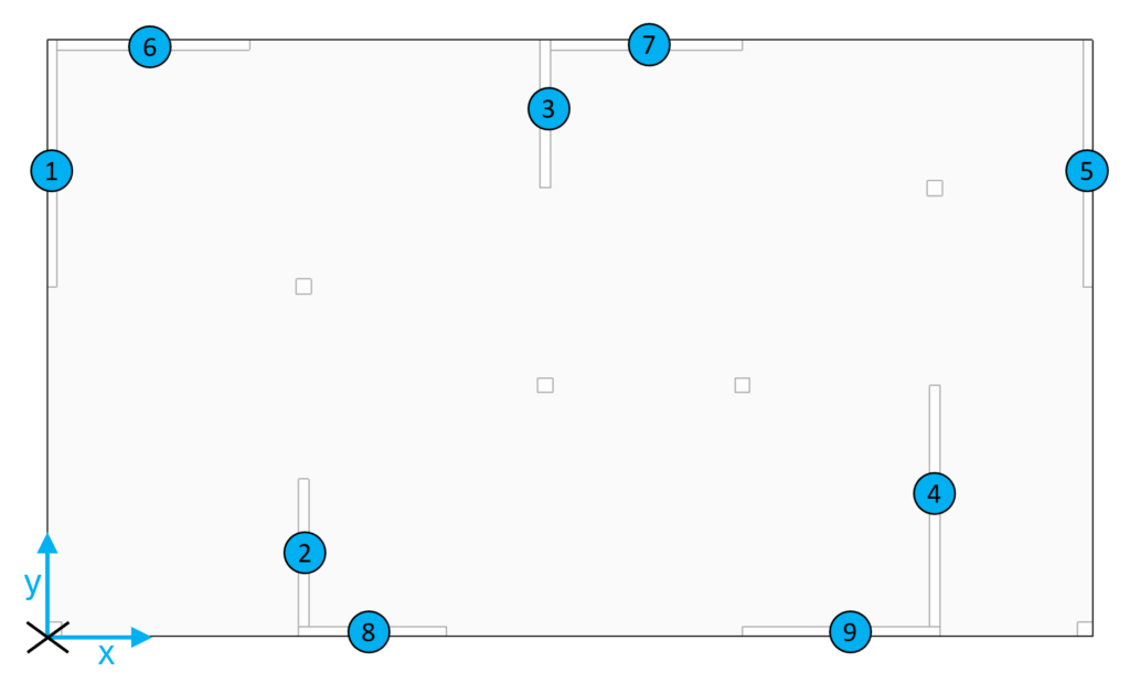
Step #3: Define the wall coordinates x and y
We define the coordinates of the center point of the walls. But first, let’s give every wall an index.
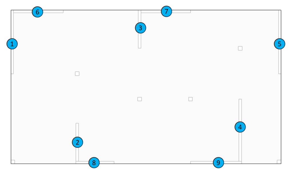
Next, we need to define the center point of the coordinate system. You can define this point anywhere. I pick the left bottom corner. And from there, we define the coordinates of the center points of the walls.
1: x1 = 0m, y1 = 9.5m
2: x2 = 5m, y2 = 1.5m
3: x3 = 10m, y3 = 10.5m
4: x4 = 18m, y4 = 2.5m
5: x5 = 21m, y5 = 9.5m
6: x6 = 2m, y6 = 12m
7: x7 = 12m, y7 = 12m
8: x8 = 6.5m, y8 = 0m
9: x9 = 16m, y9 = 0m
Step #4: Calculate the stiffness of the shear walls
The stiffness of a shear wall is calculated as:
Ci = 3⋅E⋅Iy/hw3
With an E-modulus of E=33 GPa (C30).
Stiffness of wall for length l=3m
C1 = 3⋅E⋅Iy.1/hw3 = 1.65⋅106 kN/m
Stiffness of wall for length l=4m
C2 = 3⋅E⋅Iy.2/hw3 = 3.91⋅106 kN/m
Stiffness of wall for length l=5m
C3 = 3⋅E⋅Iy.3/hw3 = 7.64⋅106 kN/m
Step #5: Calculate the total stiffness and shear centre
Total stiffness in y-direction:
Wall 1: Cy.1 = C3
Wall 2: Cy.2 = C1
Wall 3: Cy.3 = C1
Wall 4: Cy.4 = C3
Wall 5: Cy.5 = C3
Cy = Cy.1 + Cy.2 + Cy.3 + Cy.4 + Cy.5 = 2.62⋅107 kN/m
Total stiffness in x-direction:
Wall 6: Cx.6 = C2
Wall 7: Cx.7 = C2
Wall 8: Cx.8 = C1
Wall 9: Cx.9 = C2
Cx = Cx.6 + Cx.7 + Cx.8 + Cx.9 = 1.34⋅107 kN/m
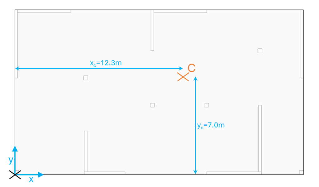
Coordinates of the shear center in y-direction
Coordinates of the shear center in x-direction
The shear center is basically the center of the diaphragm. It’s the point of the diaphragm where the diaphragm wouldn’t rotate if you apply a point load to it.
Step #6: Calculate the torsional stiffness of the shear wall system
This is the formula:
Now, let’s split this formula up and calculate all of its components.
Wall 1: VF.1 = Cy.1 ⋅ (x1 – xc)2 = 1.1571 ⋅ 109 kNm
Wall 2: VF.2 = Cy.2 ⋅ (x2 – xc)2 = 8.8114 ⋅ 107 kNm
Wall 3: VF.3 = Cy.3 ⋅ (x3 – xc)2 = 8.787 ⋅ 106 kNm
Wall 4: VF.4 = Cy.4 ⋅ (x4 – xc)2 = 2.4752 ⋅ 108 kNm
Wall 5: VF.5 = Cy.5 ⋅ (x5 – xc)2 = 5.7717 ⋅ 108 kNm
Wall 6: VF.6 = Cx.6 ⋅ (y6 – yc)2 = 9.243 ⋅ 107 kNm
Wall 7: VF.7 = Cx.7 ⋅ (y7 – yc)2 = 9.243 ⋅ 107 kNm
Wall 8: VF.8 = Cx.8 ⋅ (y8 – yc)2 = 8.1167 ⋅ 107 kNm
Wall 9: VF.9 = Cx.9 ⋅ (y9 – yc)2 = 1.924 ⋅ 108 kNm
The sum of it gives us:
VF = VF.1 + VF.2 + VF.3 + VF.4 + VF.5 + VF.6 + VF.7 + VF.8 + VF.9 = 2.5468 ⋅ 109 kNm
Step #7: Calculate the moment from the external loads
Next, we need to calculate the bending moment that acts in the center point of the coordinate system. This value depends on where you define your coordinate system. If we define the center point in the left lower corner, then we get the following bending moment.
M0 = Ry ⋅ 21m/2 = 992.25 kNm
Then we calculate the floor load moment Mw in the shear center as:
Mw = M0 – xF ⋅ Ry = -170.8 kNm
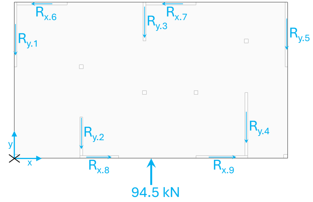
Step #8: Calculate the sectional forces of the shear walls
Finally, we calculate the sectional forces of the shear walls.
In y-direction
Wall 1: Ry.1 = Cy.1 ⋅ (Ry/Cy + (x1 – xc) ⋅ Mw/VF)= 33.84 kN
Wall 2: Ry.2 = Cy.2 ⋅ (Ry/Cy + (x2 – xc) ⋅ Mw/VF)= 6.76 kN
Wall 3: Ry.3 = Cy.3 ⋅ (Ry/Cy + (x3 – xc) ⋅ Mw/VF)= 6.2 kN
Wall 4: Ry.4 = Cy.4 ⋅ (Ry/Cy + (x4 – xc) ⋅ Mw/VF)= 24.62 kN
Wall 5: Ry.5 = Cy.5 ⋅ (Ry/Cy + (x5 – xc) ⋅ Mw/VF)= 23.08 kN
In x-direction
Wall 6: Rx.6 = Cx.6 ⋅ (Rx/Cx + (y6 – yc) ⋅ Mw/VF)= -1.31 kN
Wall 7: Rx.7 = Cx.7 ⋅ (Rx/Cx + (y7 – yc) ⋅ Mw/VF)= -1.31 kN
Wall 8: Rx.8 = Cx.8 ⋅ (Rx/Cx + (y8 – yc) ⋅ Mw/VF)= 0.78 kN
Wall 9: Rx.9 = Cx.9 ⋅ (Rx/Cx + (y9 – yc) ⋅ Mw/VF)= 1.84 kN
The shear walls take up these horizontal loads and need to be checked for it. How? Check out this article.
Final words
Alright, this is how to distribute horizontal loads according to the rigid floor method.
Hope this article helped.
If you don’t want to miss any new structural design tutorials, then subscribe to our free weekly newsletter.
Or subscribe to my YouTube channel for regular updates.
Let’s design better structures together,
Laurin.

Laurin Ernst
![Tensile Capacity of Nails [Eurocode]](https://www.structuralbasics.com/wp-content/uploads/2026/01/Tensile-capacity-of-nails-768x439.png)
![Butt Weld Design [Structural Calculation]](https://www.structuralbasics.com/wp-content/uploads/2023/09/Butt-weld-design-768x439.jpg)