From CAD to Finite Element Model
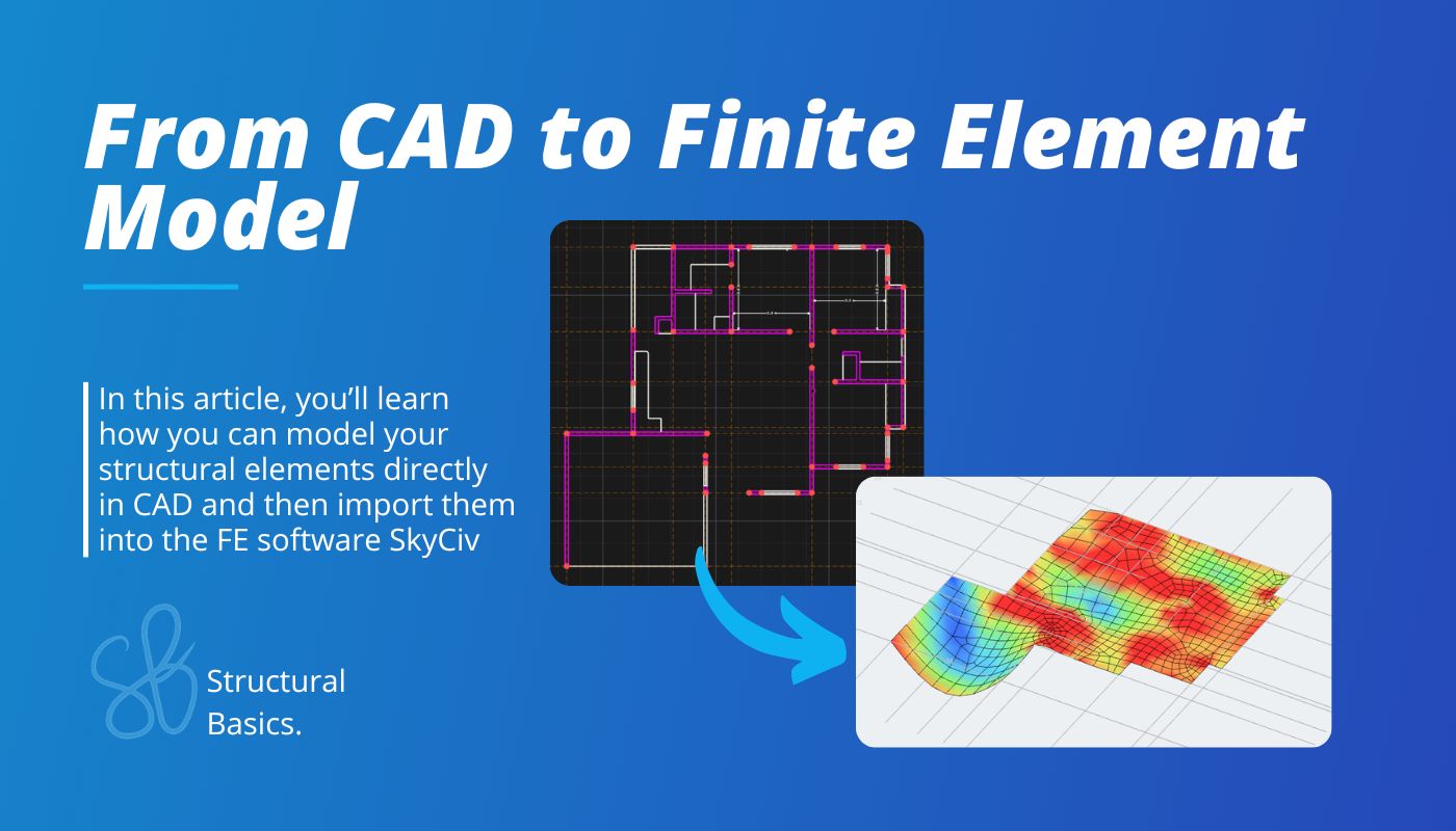
In this article, I’ll share a new tool with you that improves the workflow of creating finite element models a lot.
I’ll show you how you can model your structural elements directly in CAD and then import them into an FE software. This speeds up your modeling workflow quite a bit.
The tool I am showing you today is called CloudCAD from SkyCiv.
I am very happy that SkyCiv sponsors this episode of the Structural Basics newsletter.
And the great thing is that you can test CloudCAD for free for 30 days.
Now, let’s get into it.
The 5 Steps to Create a Finite Element Model from CAD
CloudCAD is a 2D CAD software and you can use it in 3 different ways:
- Model your structure in there from scratch
- Import a dwg, dxf or svg file from architects as a reference
- Import a pdf
For all 3 usecases CloudCAD is a great tool.
In today’s tutorial, we’ll build the finite element model of a reinforced concrete slab based on a dwg file of the ground floor of a residential building that I found online.

Step #1: Sign up for SkyCiv and open CloudCAD
SkyCiv is a web-based software, which makes it easy and fast to get started, because we don’t need to install anything.
→ Sign up here and claim your 30-Day free trial. ←
As a Structural Basics reader, you get a special deal. You get a 30-Day free trial of SkyCiv, instead of a 14-Day free trial, if you sign up for a free trial by using the Structural Basics referral link above.
Sign up with your Google account. Or if you don’t want that, just with your e-mail.
Next, in the dashboard, open the CloudCAD module.
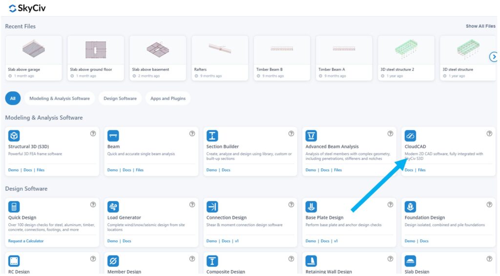
Now, you should see an empty canvas.
Step #2: The CloudCAD UI
The UI looks very clean and you find all the features you need quite quickly.
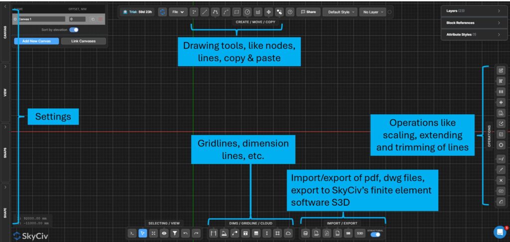
Step #3: Importing the dwg file
I downloaded a free dwg file from here: https://freecadfloorplans.com/de/haus-mit-3-schlafzimmern-und-doppelgarage/
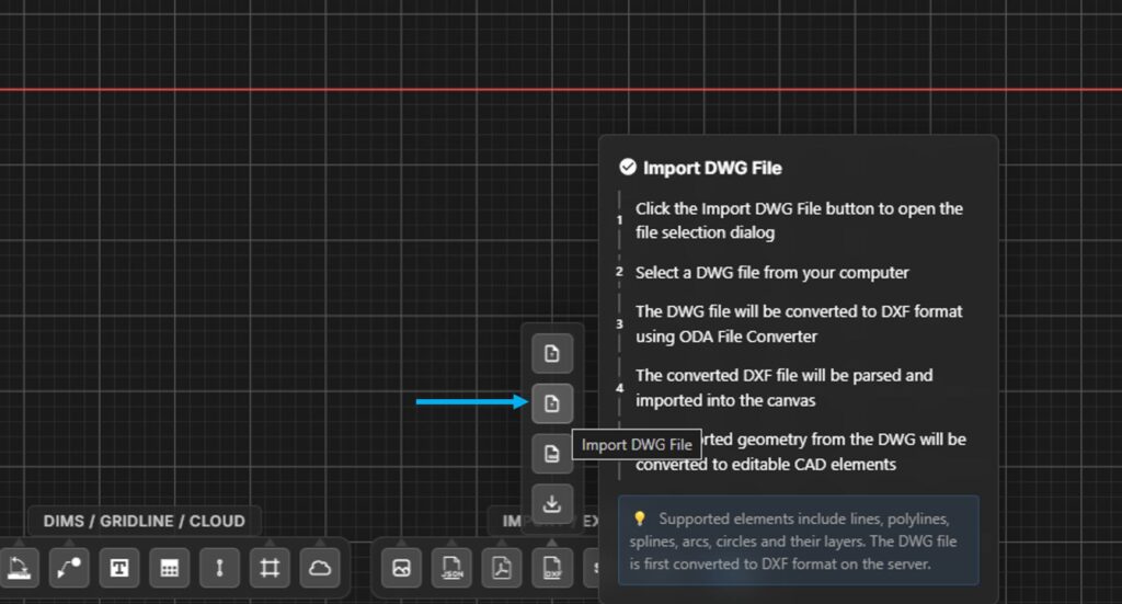
In CloudCAD we need to click on Import DWG, select the dwg file, select the unit of the dwg and click on Import.
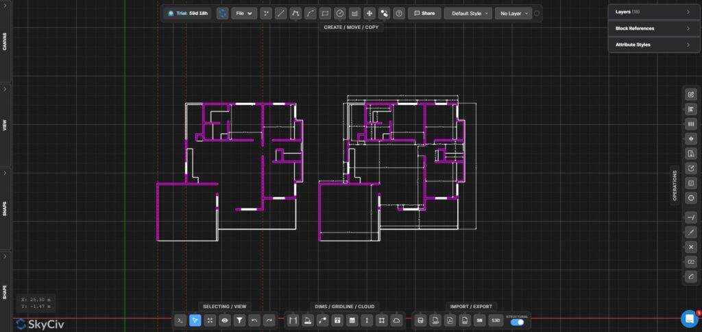
Once imported it looks like this. We can also delete one of the 2 ground floors.
The first thing we can check is whether the unit is correct.
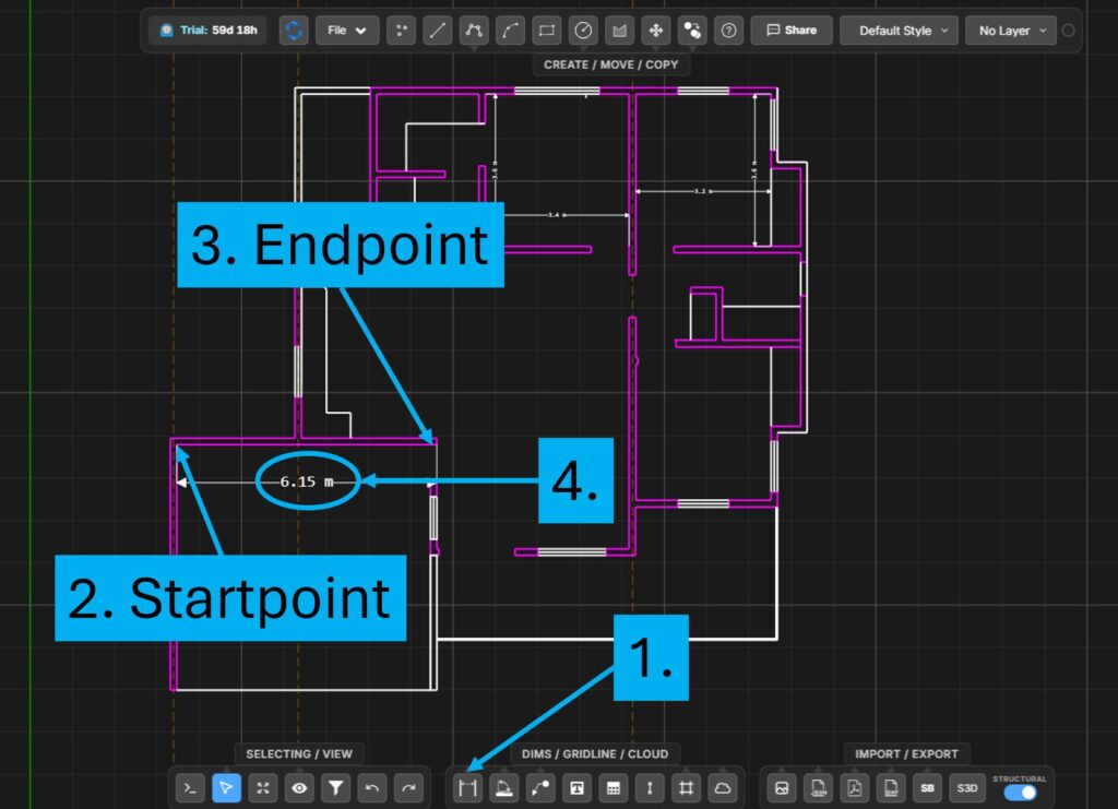
Click on (1.) Create Dimension, then the (2.) startpoint and (3.) endpoint of the (4.) dimension line.
6.15m is the correct dimension. Therefore, we don’t need to scale the dwg file.
Step #4: Modeling the structural elements
Next, we’ll model the geometry of the structural elements. In our case, we’ll model a reinforced concrete slab and I like to start off with gridlines.
With gridlines it’s much easier to then model the nodes and lines.
To draw gridlines, we click on Create Gridline (1.), then on the 1st point (2.) and then the 2nd point (3.) of the gridline.
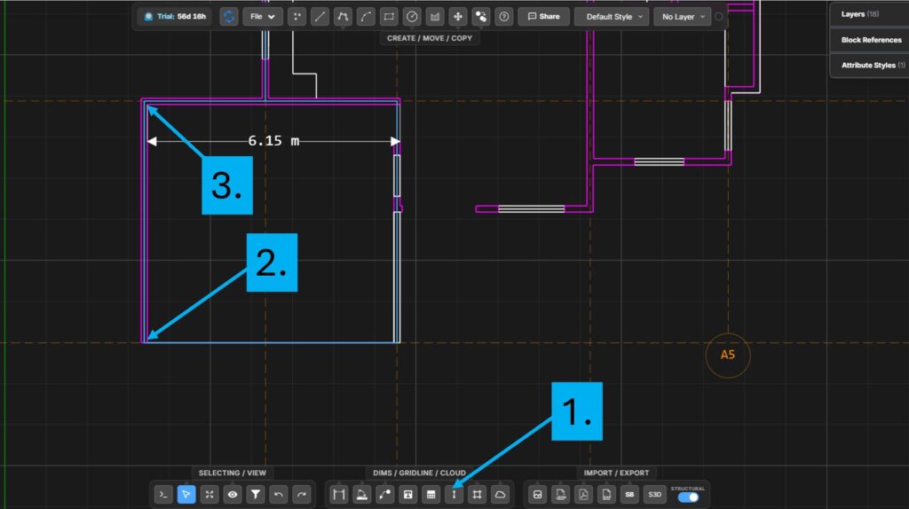
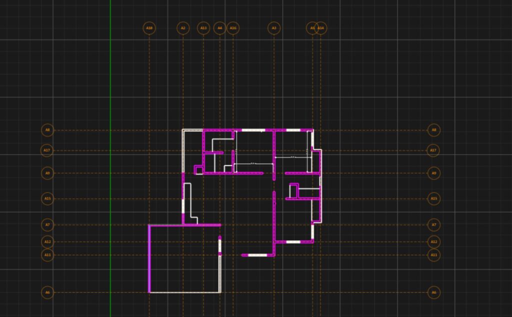
I recommend doing this for all structural walls or edges of the slab.
If you do it, it should look like this.
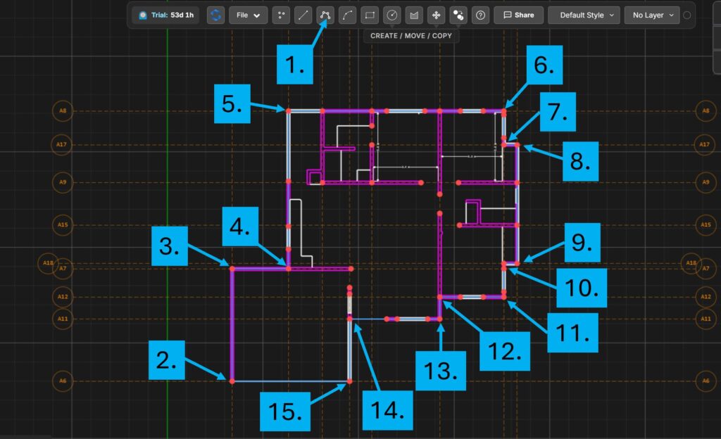
Next, we’ll add points to the start and end points of all walls.
That way, we can then easily create line supports and rc beams for the openings in SkyCiv’s finite element program S3D.
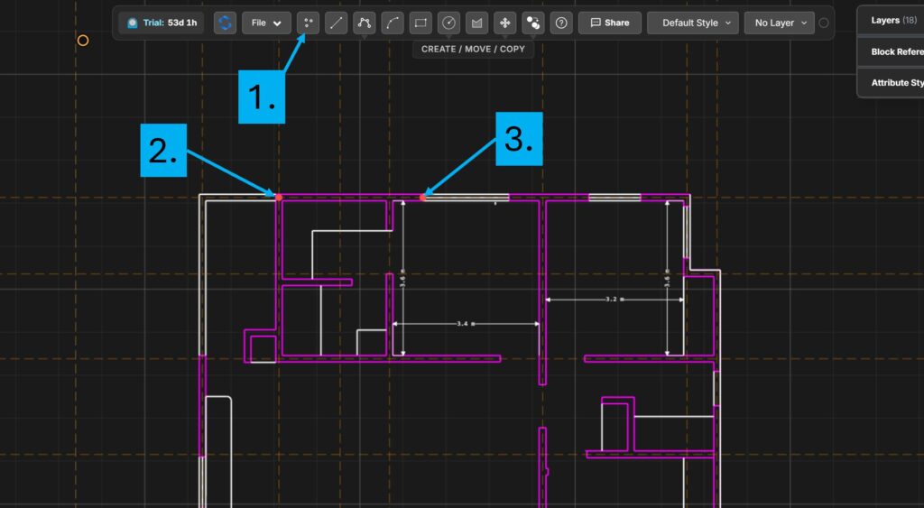
Once you’re done, it should look like this. Please note, that I often don’t use small walls as load bearing elements if there are many load bearing walls near to it. Then I usually tell the architect that these walls should be non-load bearing.
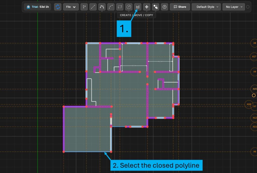
As a last step in CloudCAD, we’ll create the slab as a hatch.
The easiest way to create the hatch is by creating a closed polyline of the slab edges and then selecting this polyline with the hatch command.
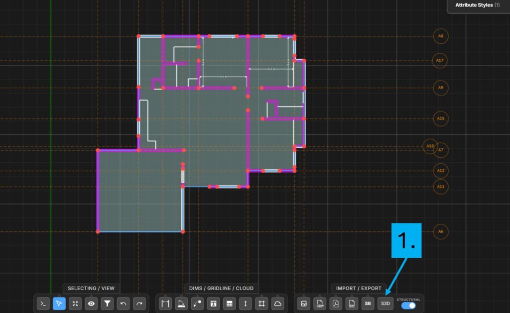
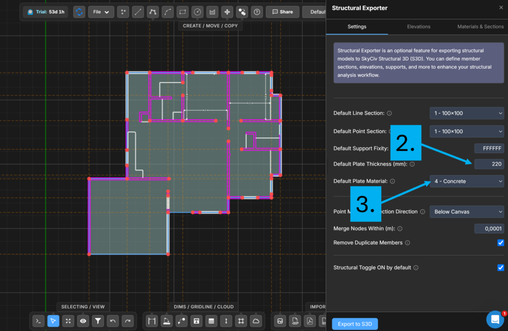
To export the model to the finite element software S3D, we’ll click on S3D (1.), type in the slab thickness (2.) and concrete as the material (3.). Then click on Export to S3D.
In S3D the model should look like this.
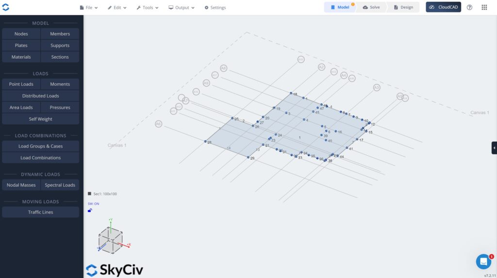
Step #5: Adding supports, loads and beams in the finite element software
This workflow with CloudCAD is really fast, but we still have to add a few things in the finite element software.
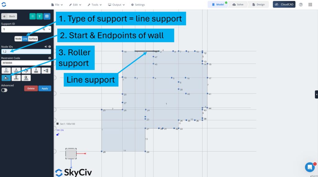
First let’s add the line and point supports which are walls and columns. This feature will be added to CloudCAD soon. But for now we need to do it in SkyCiv S3D.
Click on Supports → Line → Node ID’s of the start and end nodes (e.g. 1 and 2) → 3D roller support → Apply.
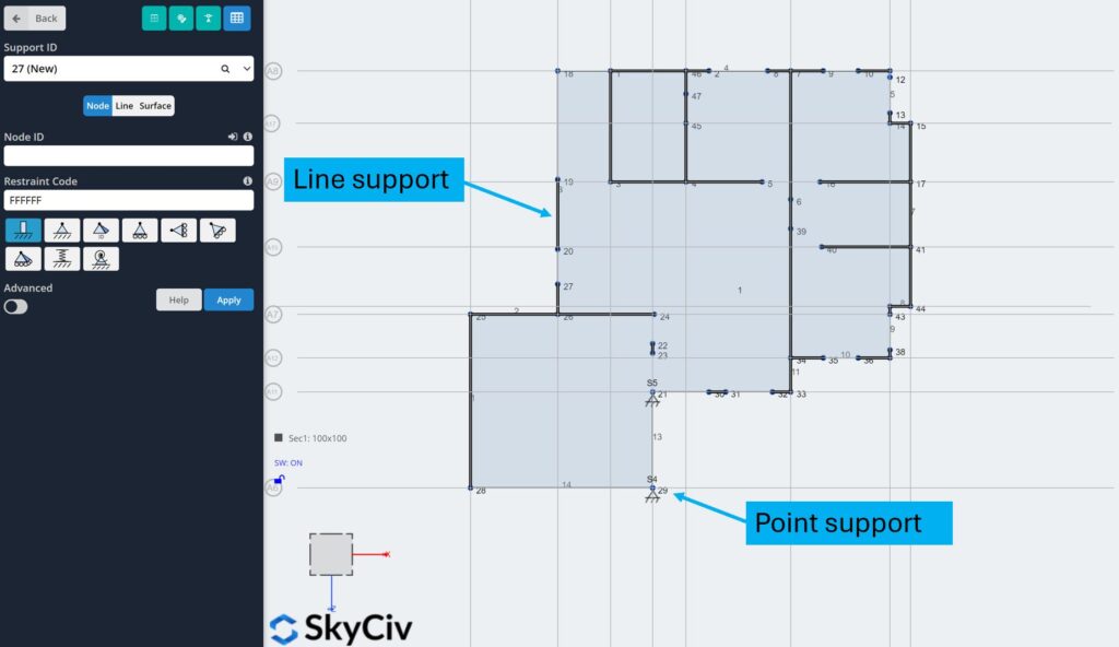
Once you have added all supports the model looks like this.
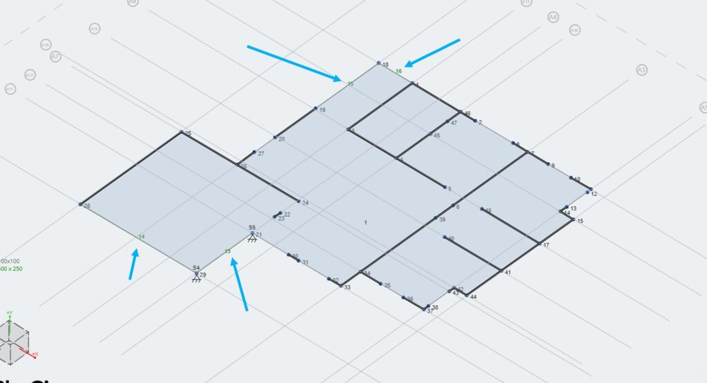
For some of the big wall openings and cantilevered parts of the slab I want to add reinforced concrete beams. This adds stiffness to the slab and the deflection will be smaller.
Click on Sections → Section builder → Shape Templates (1.) → Rectangular (2.) → Material: Concrete (3.) → Change the dimensions to whatever you want; in this tutorial I’ll use 250mm as a width and 400mm as a height (4.) → Click on submit (5.)
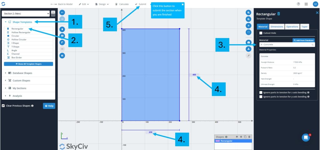
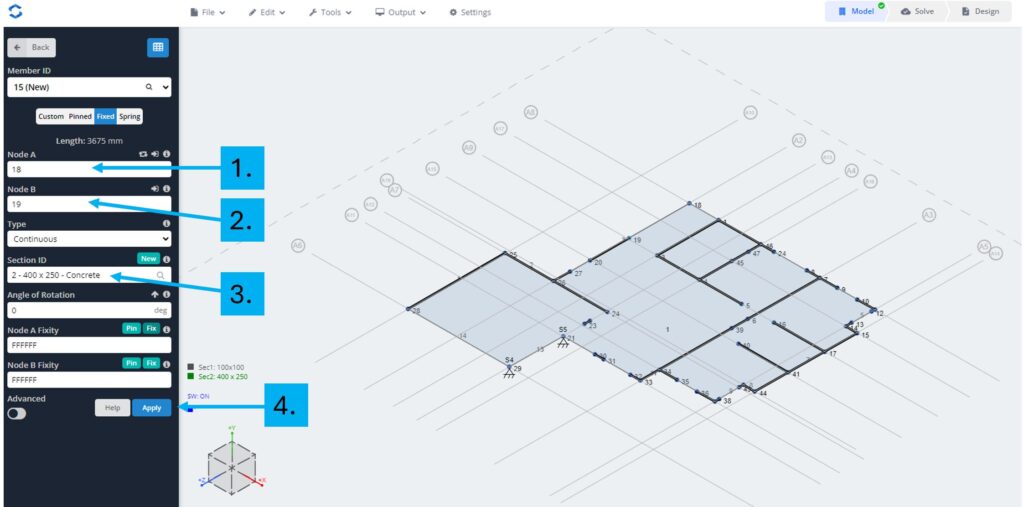
Click on Member → Node A = 18 (1.) → Node B = 19 (2.) → Section ID: select the section you just created (3.) → Click Apply (4.)
I did this now for 4 cantilevered parts or bigger wall openings.
Next, we’ll add loads and create load combinations.
To activate the self-weight, click on self-weight → Apply.
Then, click on Pressures → Plate ID = 1 (1.) → Y Magnitude = 2.0 kPa/kN/m2 (2.) → Load group = g_k for dead load (3.) → Click on Apply (4.)
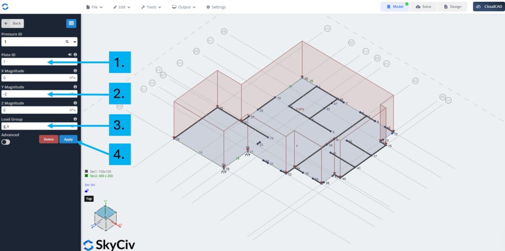
Repeat the same for the live load of 2.5 kN/m2.
Now we click on Load Combinations. You can create load combinations manually or with the load combination generator automatically.
Click on Load Combination Generator, select your region and your national annex → Click on Load Groups → Change the live load from dead load to Live – Domestic and residential → Click on patterns → Click on Generate Load Combinations → Check the preview if everything looks fine then click on Import.
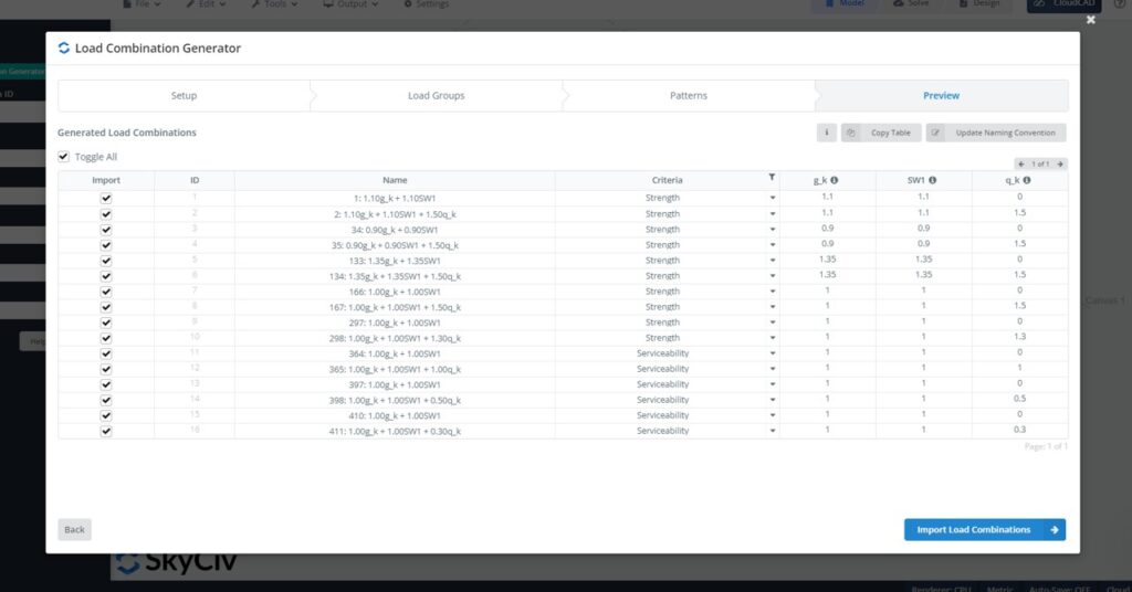
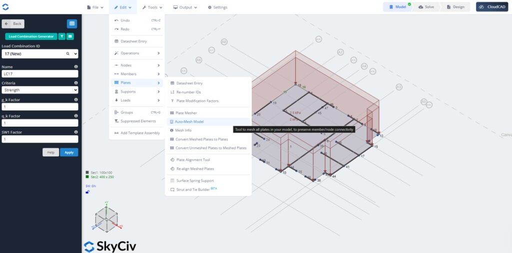
As the last step before running the FE analysis we need to mesh the slab.
Click on Edit → Plates → Auto-Mesh Model. Automeshing the model is fine for a typical residential slab.
To run the analysis, click on Solve (1.) and then on Linear Static (2.).
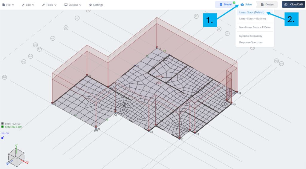
You can now view the results like deflection, bending moments and shear forces and much more.
If you want to learn more about how to interprete and verify FE results, you can check out the following ressources:
- How to Design RC Slabs with SkyCiv (finite element software)
- FEA for Beginners: 3D Frame Design Using SkyCiv (YouTube tutorial)
- How to Verify RC Slabs: From FE Analysis to Reinforcement Sketches (E-Book – Module #3)
It would be too much to cover this also in this tutorial.
Other CloudCAD Features
Before finishing this tutorial I wanted to share all the other features that CloudCAD has which we didn’t cover in this tutorial.
- Import and Export DXF, DWG, PDF, SVG & PNG
- Convert Structural 3D models to 2D floorplans & elevations; this means that CloudCAD also works the other way around. You can export your model from S3D to CloudCAD
- Fully functional CAD software for Mac and Windows. With CloudCAD you can create professional engineering drawings
- Comprehensive suite of drawing commands and operations
- Support for layers, blocks & attribute styles.
- Command-line & search functionality.
- Customizable keyboard shortcuts.
- Detailed tutorials and software documentation.
Give it a try and test it for free for 30 days!
Final words
Now you have created your first FE model of an in-situ concrete slab from an architectural drawing.
I personally like this workflow alot. It’s intuitive, and you can improve your workflow from architecutral drawings to FE model a lot.
Thank you, SkyCiv, for sponsoring this Structural Basics article.
Let’s design better structures together,
Laurin.
P.S.: In case you missed the SkyCiv trial link, here’s another chance to claim your 30-day free trial and get started with CloudCAD and an FE-program today.

Laurin Ernst

![Rafter Roof Design [Step-By-Step Guide]](https://www.structuralbasics.com/wp-content/uploads/2022/04/Rafter-Roof-Design-1-768x439.jpg)