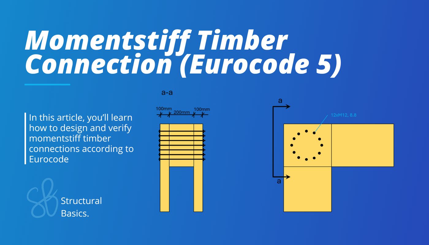
Momentstiff Timber Connection (Design Guide EC5)
A major difference between timber and reinforced concrete or steel is that most timber elements are simply supported with hinged connections, because moment‑stiff connections are much more difficult to design in timber.
But it is possible to design moment stiff timber connections.
Timber warehouses and sport halls with frames often have moment stiff connections in their corners.
I have also designed a few moment stiff connections like a frame in an industrial hall which just seperated 2 rooms.
In this article, I am gonna show you how to design and verify moment stiff frame corners..
Now, let’s get into it.
The 5 Steps To Calculate The Moment Capacity of a Bolted Timber Connection According To Eurocode
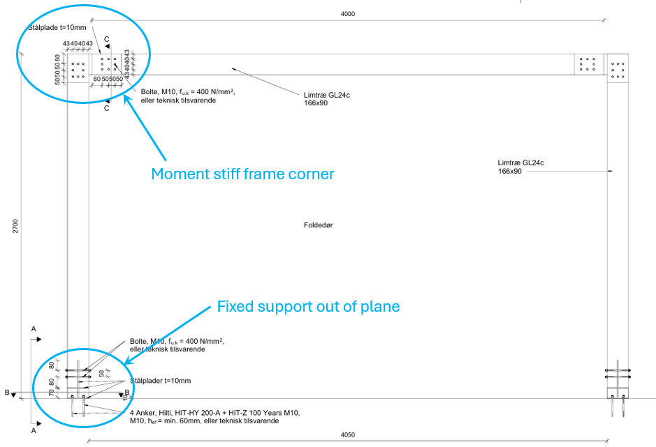
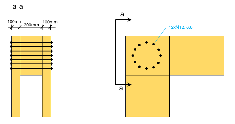
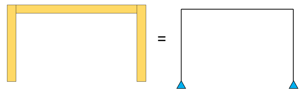
Here’s the frame corner we’ll verify for bending in today’s tutorial.
A circular pattern of the connectors is most common as the radial distance to the centroid of the connection is the same for each bolt. This means that each bolt will have the same utilisation which is the most economic solution.
Step #1: Define the geometrical properties of the timber elements and connectors
The elements have the following dimensions:
- Thickness inner timber element: t2=200mm
- Thickness outer timber elements: t1=100mm
- Bolt diameter: d=12mm
- Washer diameter: dw=40mm
- Washer thickness: tw=6mm
- Check (EN 1995-1-1 8.5.2 (3)): dw < min(12 ⋅ tw; 4 ⋅ d) = 1 → OK!
- Stress area of the bolt (threaded part): As=84.3 mm2
- Contact area washer: Aw=(dw/2)2 – (d/2)2=364 mm2
- Number of bolts: nb=12
Step #2: Define the material properties of the timber and connectors
Here are the strength and stiffness properties that we need in the calculation:
- Ultimate tensile strength bolts, 8.8: fu=800 MPa
- Partial factor (EN 1995-1-1 Table 2.3): γM = 1.3
- Modification factor (EN 1995-1-1 Table 3.1): kmod = 0.9
- Density of the timber element: ρk = 350 kg/m3
- Partial factor for resistance of cross-sections in tension to fracture (EN1993-1-1 6.1 (1)): γM2 = 1.25
- Compressive strength perpendicular to grain C24: fc.90.k=2.5 MPa
Step #3: Calculate the loads acting on the connection
In this step we need to calculate the characteristic loads that act on the frame and the internal forces that occur in the frame corner.
We won’t show how to calculate the loads and how to do the load transfer in this newsletter, as each calculation of the individual load is an article for itself and load transfer is also a big topic. If you want to learn how to transfer loads from one structural element to the next, you can check out Module #2 Structural Design of a Residential Timber Roof.
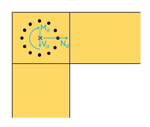
In this newsletter, we’ll verify the moment stiff connection for the following internal forces.
Bending moment:
Md = 24 kNm
Shear force:
Vd = 60 kN
Normal force:
Nd = 10 kN
Step #4: Calculate the loads acting on the bolts
In step #4, we calculate the loads that act on the bolts. The shear force V_d and the normal force N_d can be equally distributed to the bolts. But the loads due to the bending moment depend on the radial distance r.
Loads on one bolt due to the shear force:
Fv.d = Vd/nb = 5.0 kN
Loads on one bolt due to the normal force:
Fh.d = Nd/nb = 0.83 kN
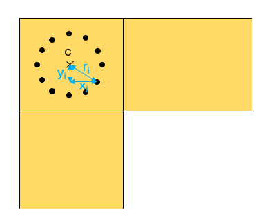
The max. load on a bolt due to the bending moment is calculated as:
$$F_{m.d.max} = M_d \cdot \frac{r_{max}}{\sum_{i=1}^{n} r_i^2}$$
With,
- rmax = max. radial distance of the bolts
- ri = radial distance of each bolt
For a circular pattern this formula translates to
Fm.d = Md ⋅ r/Ip = 10.0 kN
With,
- r =200mm; radial distance of the bolts
- Ip = nb ⋅ r2; polar moment of inertia of the bolted connection
The resultant load on one bolt due to these 3 loads is then calculated as:
$$F_{d} = \sqrt{(F_{v.d} + F_{m.d})^2 + F_{h.d}^2} = 15.0 kN$$
Step #5: Shear design verification of the bolted connection
The tensile capacity of the bolt is determined by the tensile strength of the bolt and the compression capacity perpendicular to the grain due to the the washer area.
Tensile capacity of the bolt
The capacity is actually calculated with the Steel Eurocode as it’s a steel connector.
For bolts other than countersunk bolts (EN 1993-1-8 Table 3.4):
k2 = 0.9
Tensile capacity bolt (EN 1993-1-8 Table 3.4):
Ft.Rd = (k2 ⋅ fub ⋅ As)/γM2 = 48.6 kN
The tensile capacity of bolts is super high and usually not the critical part.
Capacity of the washer
The load-bearing capacity of the washer equals the compressive strength of the contact area (EN1995-1-1 8.5.2 (2)):
Fw.Rk = 3 ⋅ fc.90.k ⋅ Aw = 2.73 kN
As the compressive strength of the contact area is much lower than the tensile capacity of the bolt Fax.Rk = Fw.Rd.
Characteristic embedment strength for the outer timber elements (EN1995-1-1 (8.32)):
fh.k.1 = 0.082 ⋅ (1 – 0.01 ⋅ d) ρk N/mm2 = 25.3 N/mm2
Characteristic embedment strength for the inner timber elements (EN1995-1-1 (8.32)):
fh.k.2 = fh.k.1
Yield moment (EN1995-1-1 (8.14)):
My.Rk = 0.3 ⋅ fu ⋅ d2.6 = 153.5 kNmm
Timber-to-timber connections according to EN1995-1-1 8.2.3 (double shear)
β = fh.k.1/fh.k.2 = 1.0
EN1995-1-1 (8.7g):
Fv.Rk.g = fh.k.1 ⋅ t1 ⋅ d = 30.3 kN
EN1995-1-1 (8.7h):
Fv.Rk.h = 0.5 ⋅ fh.k.1 ⋅ t2 ⋅ d = 30.3 kN
EN1995-1-1 (8.7j):
$$F_{v.Rk.j} = 1.05 \cdot \frac{f_{h.k.1} \cdot t_1 \cdot d}{2 + \beta} \cdot (\sqrt{2 \cdot \beta \cdot (1 + \beta) + \frac{4 \cdot \beta \cdot (2 + \beta) \cdot M_{y.Rk}}{f_{h.k.1} \cdot d \cdot t_1^2}}- \beta) + \frac{F_{ax.Rd}}{4} = 30.3 kN$$
EN1995-1-1 (8.7k):
$$F_{v.Rk.k} = 1.15 \cdot \sqrt{\frac{2 \cdot \beta}{1 + \beta}} \cdot \sqrt{2 \cdot M_{y.Rk} \cdot f_{h.k.1} \cdot d} + \frac{F_{ax.Rk}}{4} = 11.8 kN$$
Characteristic shear capacity per bolt per shear plane:
Fv.Rk = min(Fv.Rk.g; Fv.Rk.h; Fv.Rk.j; Fv.Rk.k) = 11.8 kN
Design shear capacity:
Fv.Rd = 2 ⋅ kmod ⋅ Fv.Rk/γM = 16.3 kN
The shear capacity is multiplied by 2 because the formulas from 8.2.3 are in regards to one shear plane. Our connection has 2 shear planes and therefore we can multiply the shear capacity by 2.
Verification:
η = Fd/Fv.Rd = 0.92
Final words
Alright, this is how you verify a bolted timber-to-timber moment stiff connection according to Eurocode.
Hope this article helped.
If you don’t want to miss any new structural design tutorials, then subscribe to our free weekly newsletter.
Or subscribe to my YouTube channel for regular updates.
Let’s design better structures together,
Laurin.

Laurin Ernst