Continuous Beams Explained {2024}
Structural frames are a static system commonly used for structures like bridges, foundation beams, timber roofs, steel rafters and trusses. They are characterized by having more than 2 supports, which leads to smaller deflections compared to the simply supported beam.
In this guide, I’ll show you, what continuous beams are, which static systems exist and real-world examples of continuous beams.
So let’s get into it. 🚀🚀
What is a Continuous Beam?
A continuous beam is a static and structural system that spans over multiple supports (more than 2). This is beneficial for long spans, because the deflection and bending moment are smaller than for simply supported beams with the same load and span.
Continuous beams are statically indeterminate, which means that the reaction forces and internal forces can’t be calculated by the 3 equilibrium equations.
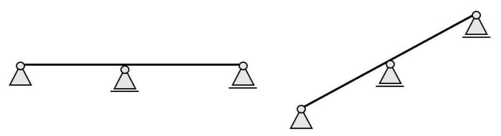
In most cases, continuous beams are horizontal beams. However, in some cases like 3-span roof rafters, continuous beams can also be inclined.
The Static Systems Of The Continuous Beam
The continuous beam has 2+ supports. It could have 3, 4 or 12 supports.
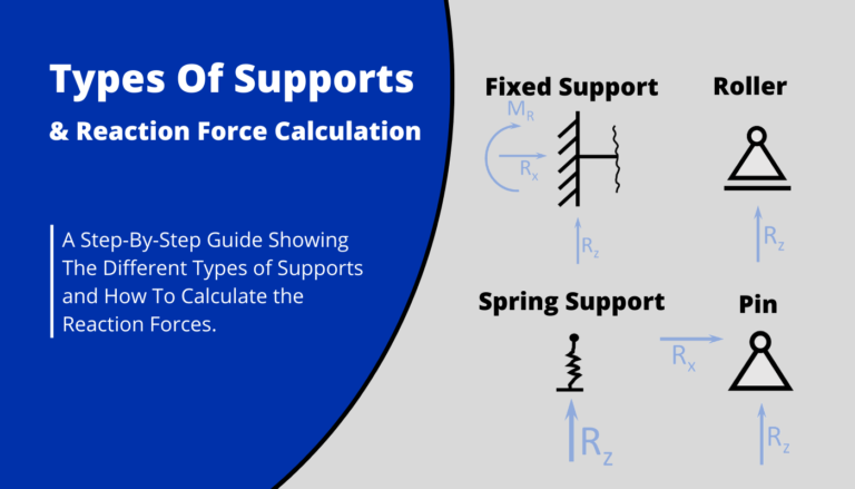
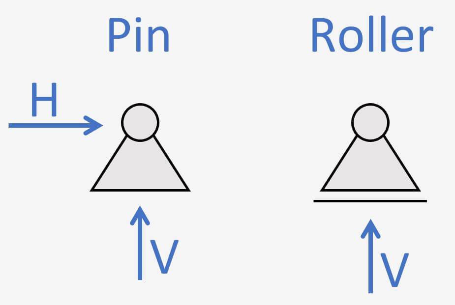
It has 1 pin support and the rest of the supports are roller supports.
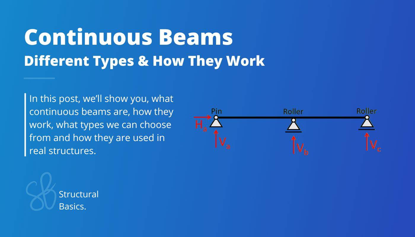
1. 2-span continuous beam
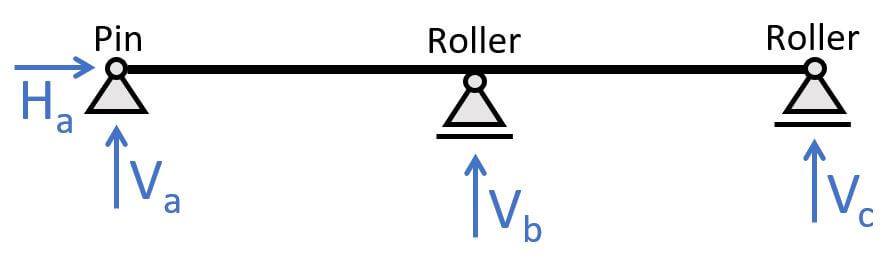
The 2-span continuous beam is categorized by having 1 pin and 2 roller supports. The static system is indeterminate, which means we can’t calculate the reaction forces with the 3 equilibrium equations. (You can find formulas a bit further down in this post.) The pinned support (a) takes up
- a vertical reaction force V
- a horizontal reaction force H
And the roller supports (b) & (c) take up
- a vertical reaction force V
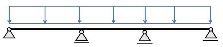
2. 3-span continuous beam
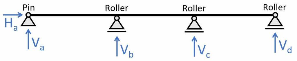
The 3-span continuous beam is categorized by having 1 pin and 3 roller supports. The static system is indeterminate, which means we can’t calculate the reaction forces with the 3 equilibrium equations. (You can find formulas a bit further down in this post.) The pinned support (a) takes up
- a vertical reaction force V
- a horizontal reaction force H
And the roller supports (b) & (c) take up
- a vertical reaction force V
3. X-span continuous beam
You can add as many supports as you want. There are structures like cable-stayed bridges or foundation beams that have often more than 10 supports.
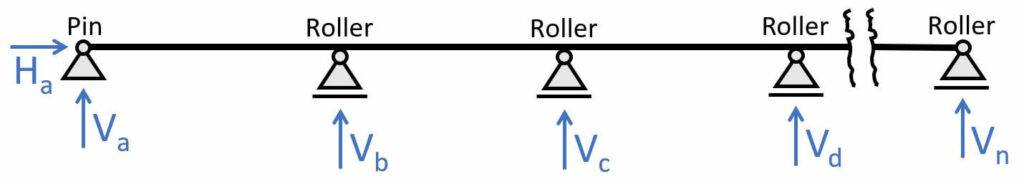
The x-span continuous beam is categorized by having 1 pin and x roller supports. The static system is also indeterminate, which means we can’t calculate the reaction forces with the 3 equilibrium equations.
For continuous beams with many supports we mostly use FE programs as it’s probably bigger and more complex structures.
The pinned support (a) takes up
- a vertical reaction force V
- a horizontal reaction force H
And the roller supports (b), (c), (d) & (…) take up
- a vertical reaction force V
Example Structures of Continuous Beams
Continuous beams commonly used in structures. One of their benefits is a much smaller deflection as for simply supported beams for the same load and span.
Here are a few real-world examples:
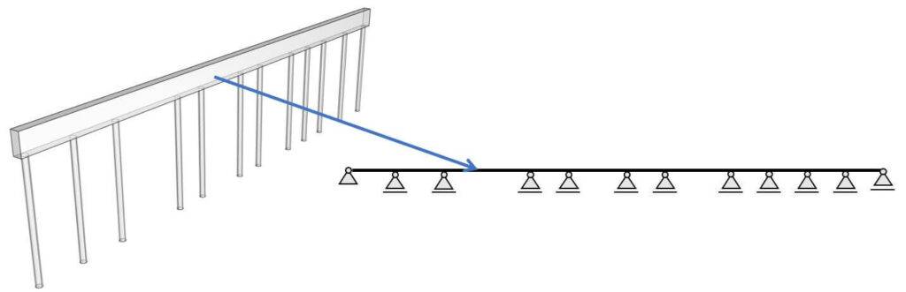
1. Foundation beams supported by pile foundations
Foundation beams are used to support walls, columns and concrete slabs and to distribute those vertical loads to the pile foundations and then to the soil. 👇👇
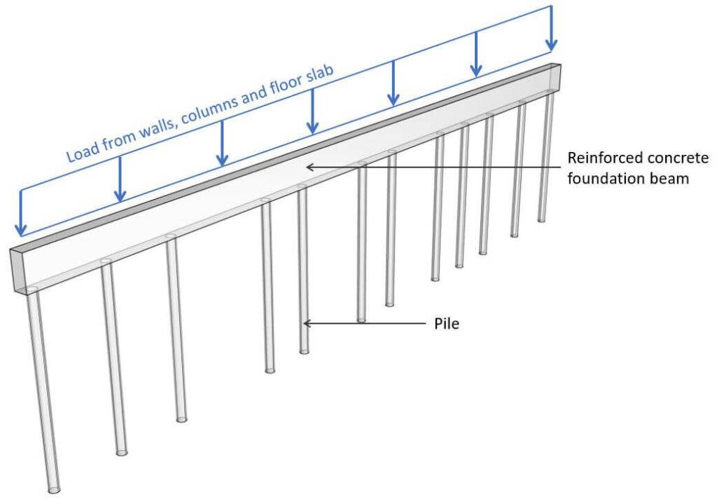
On the projects, where I have used foundation beams, the spacing of the piles wasn’t the same as the spacing of the columns and walls wasn’t the same either.
Now, you use foundation beams on projects with big loads where strip foundations aren’t enough, and you need to use pile foundations.
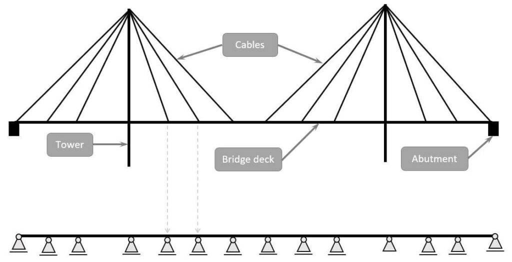
2. Cable-stayed bridges
For a very early design, the cables of a cable-stayed bridge can be modelled as rollers and later as spring supports. This makes the bridge deck a continuous beam.
3. Chords of trusses
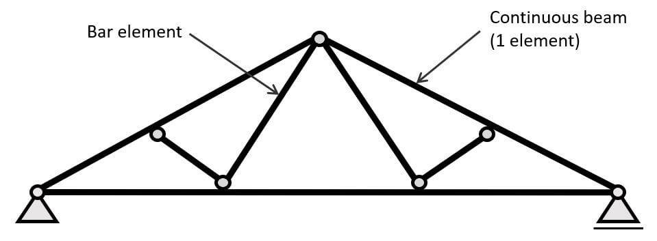
In the old days, trusses were calculated with hinge connections in every node. We also learn to calculate the normal forces for trusses of that kind in university, because having continuous elements makes the static system statically indeterminate.
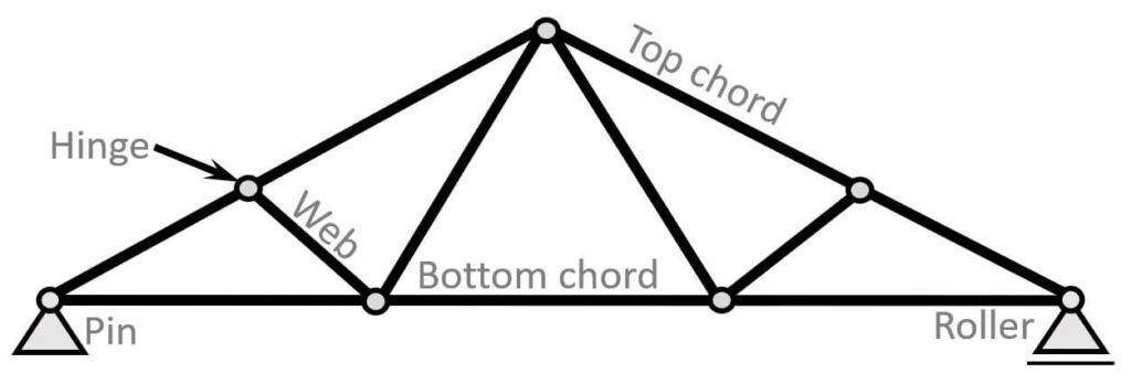
However, most trusses have continuous chords, because it’s easier to construct to have fewer connections. And in this case, hinges are precise when the element is actually continuous because bending moments and shear forces are not considered. So, we should model the chords continuous if they are 1 element.
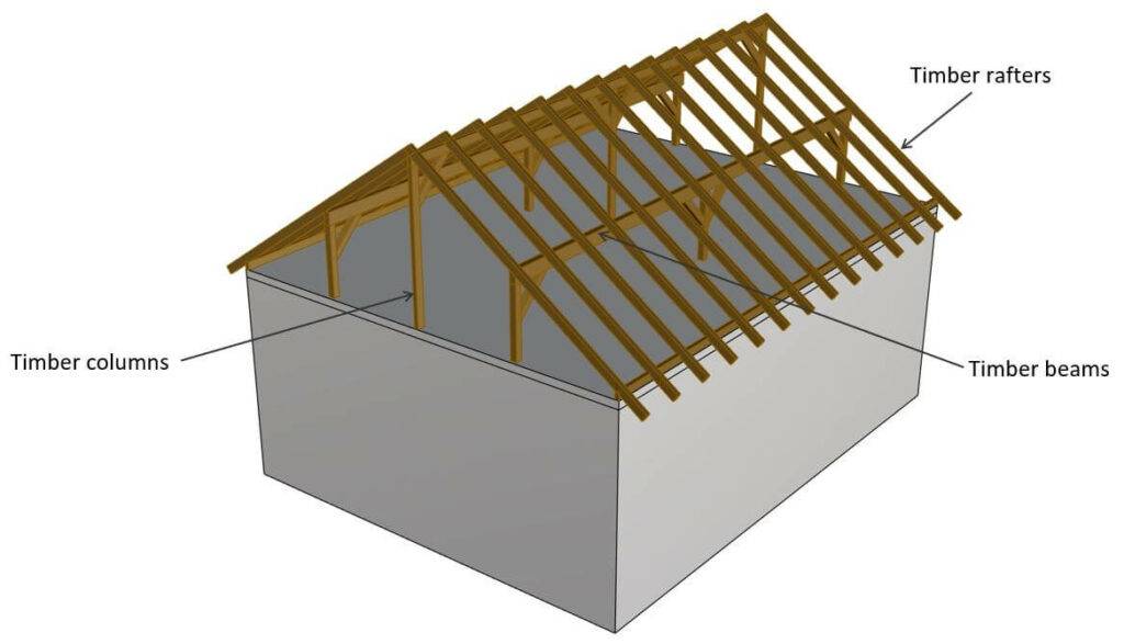
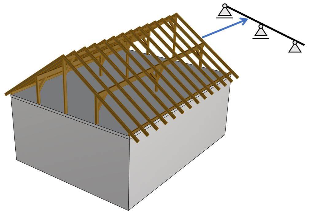
4. Timber rafters supported by 3 beams
Timber rafters of a roof structure are usually supported by 3 horizontal timber beams. In this case, the rafters are inclined continuous beams.
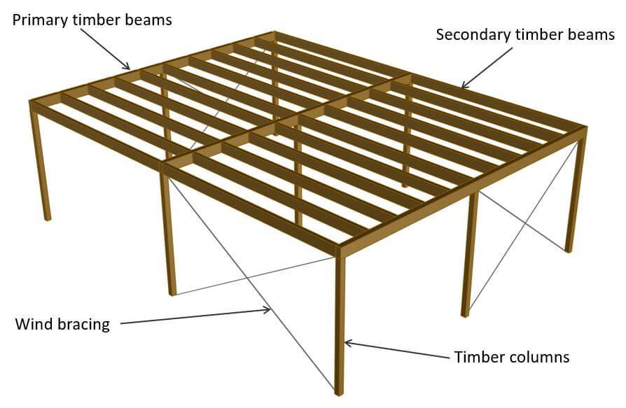
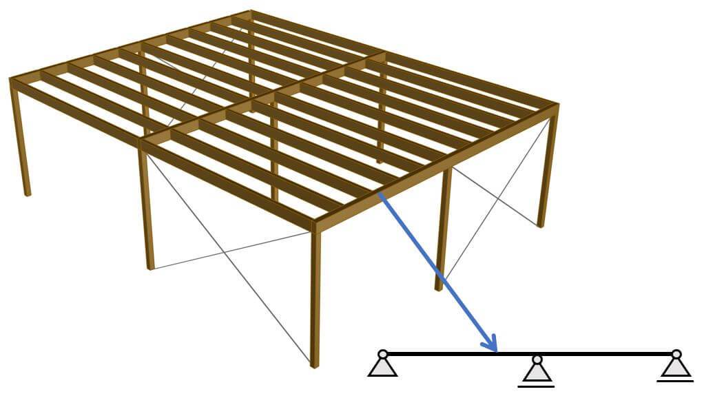
5. Timber primary beams
The primary beams of timber flat roof which support secondary beams are continuous if they have more than 2 supports, as in the example below. The external area loads like dead, snow and live load are applied to the primary beams and transferred to the primary beams.
Formulas for internal forces due to different loading situations
You can find all the formulas for bending moment and shear forces due to different loading situations on these pages: 👇👇
We’ll now show some example from those pages.
2-span continuous beam – UDL on one span
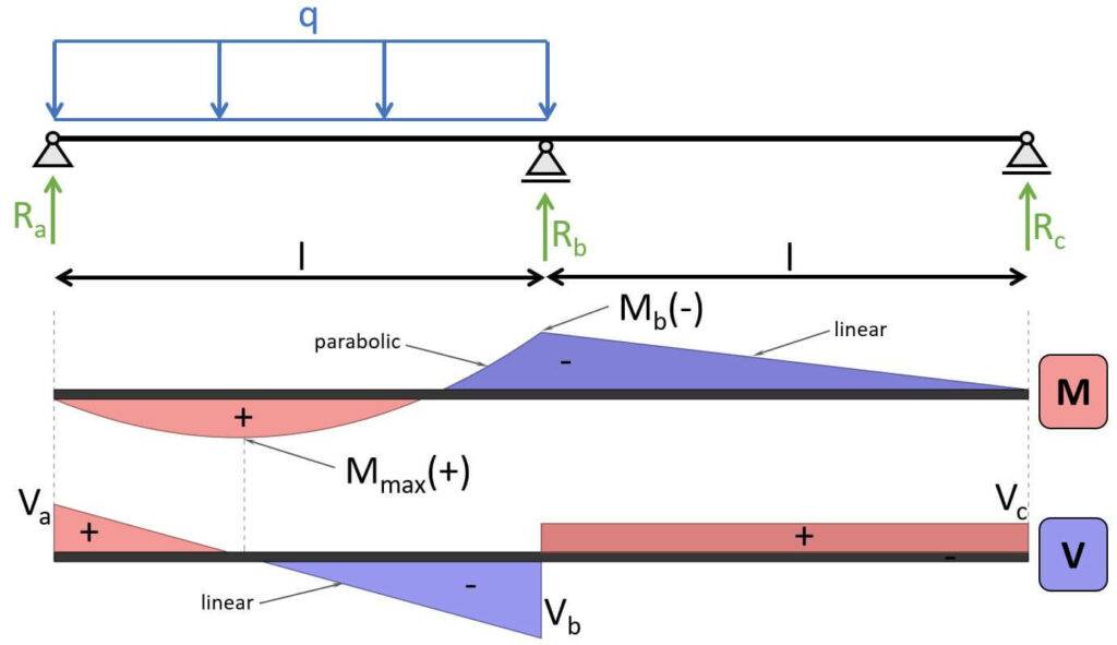
Max. positive bending moment:
$$M_{max} = 49/512 \cdot q \cdot l^2$$
Max. negative bending moment:
$$M_{max} = -1/16 \cdot q \cdot l^2$$
Shear force (at support a):
$$V_{a} = 7/16 \cdot q \cdot l$$
Shear force (at support b):
$$V_{b} = -9/16 \cdot q \cdot l$$
Shear force (at support c):
$$V_{c} = 1/16 \cdot q \cdot l$$
3-span continuous beam – UDL on 2 neighbouring spans
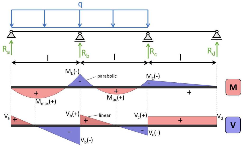
Max. positive bending moment:
$$M_{max} = 0.0735 \cdot q \cdot l^2$$
Max. negative bending moment (at support b):
$$M_{b} = -0.117 \cdot q \cdot l^2$$
Shear force (at support a):
$$V_{a} = 0.383 \cdot q \cdot l$$
Shear force (at support b):
$$V_{b(-)} = -0.617 \cdot q \cdot l$$
$$V_{b(+)} = 0.583 \cdot q \cdot l$$
Shear force (at support c):
$$V_{c(-)} = -0.417 \cdot q \cdot l$$
$$V_{c(+)} = 0.033 \cdot q \cdot l$$
Shear force (at support d):
$$V_{d} = 0.033 \cdot q \cdot l$$
4-span continuous beam – UDL on all 4 spans
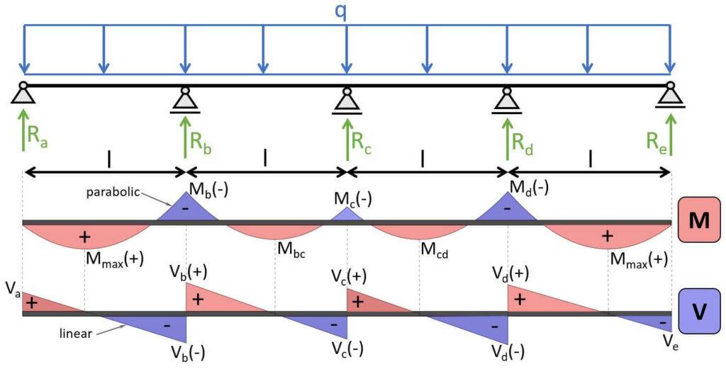
Max. positive bending moment:
$$M_{max} = 0.077 \cdot q \cdot l^2$$
Max. negative bending moment (at support b & d):
$$M_{b} = M_d = -0.107 \cdot q \cdot l^2$$
Shear force (at support a & e):
$$V_{a} = V_{e} = 0.393 \cdot q \cdot l$$
Shear force (at support b & d):
$$V_{b(-)} = V_{d(+)} = -0.536 \cdot q \cdot l$$
$$V_{b(+)} = V_{d(-)} = 0.607 \cdot q \cdot l$$
Shear force (at support c):
$$V_{c(-)} = V_{c(+)} = 0.464 \cdot q \cdot l$$
Conclusion
Continuous beams are a static system we use for many structures in structural engineering. I use it a ton in my job as a structural engineer because of their benefits of a smaller deflection and smaller bending moments compared to simply supported beams with the same span.
They are also quicker to install as there are fewer connections.
Hopefully, this gave you an overview and good understanding of how continuous beams work and where we use them in structural engineering.
There are many other static systems that we use in our structural design. Check them out here: 👇👇

![Understand Bending Moments [Everything YOU Need To Know – 2024]](https://www.structuralbasics.com/wp-content/uploads/2023/05/Bending-moment-768x439.jpg)
![The Pratt Truss Explained [2024]](https://www.structuralbasics.com/wp-content/uploads/2022/12/Pratt-truss-explained-768x439.jpg)