Understand Bending Moments [Everything YOU Need To Know – 2026]
Do you need to calculate bending moments in uni but didn’t understand a thing? 🤔🤔
It’s indeed difficult. It took me personally 2-3 months to fully understand it.
So in this blog post, we’ll explain what a bending moment is and how to calculate it step-by-step.👍👍
We’ll also add real-world examples of bending moments, which you usually don’t see in uni. 👀👀
Alright, let’s talk BENDING MOMENTS. 🚀🚀
What Is A Bending Moment?
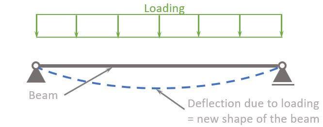
A bending moment describes the internal force that leads to bending of a structural element such as a beam due to loading.
In easier words, a bending moment refers to the tendency of a structural element to deform due to external loading (self-weight, snow, wind, people etc.).
Now, bending moments appear at any location of the beam, and it’s visualized as a circular arrow. ↩️↩️
As it appears at any point of the beam, we cut the beam. This is done to calculate the internal forces, such as bending moments. We have already written a more detailed article about the internal force calculation.
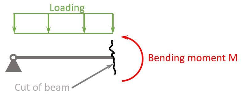
Due to this bending moment, the beam experiences compression in the top part and tension in the bottom part. The point along the beam where the bending moment is zero is called the neutral axis.
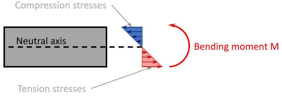
In the picture, you can also see that the biggest stresses – compression and tension – appear in the most outer fibres of the beam.
And as you can imagine, the bigger the bending moment, the bigger the compression and tension forces.
But how does the bending moment increase?
Well, we’ll calculate the bending moment in a second, but in general we can say that the bending moment increases due to
- increased loading
- increased span
- increased stiffness
Now, let’s have a look at how we determine the magnitude of a bending moment. 👇👇
Bending Moment Calculation
Bending moments are calculated as
$$Force \cdot lever arm$$
Alright, if you googled how to calculate a bending moment, you probably don’t know what a force or a lever arm is. Let’s explain it with a figure. 🖼️🖼️
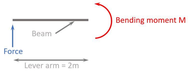
So the moment M in a specific point of a beam element is calculated by a force $\cdot$ lever arm. The lever arm is the parallel distance to the point.
In the case above, if the force is 5 kN, then the moment is calculated as:
$$M = 5 kN \cdot 2m = 10 kNm$$
Moments can be calculated at any location of a beam. If the beam is 5 m long, then we could have calculated the moment also with a lever arm of 3.1 m or 4.5 m.
In most cases, we have more than 1 load that need to be considered in the bending moment. So let’s look at the example from above, where we applied a line load and cut the beam.
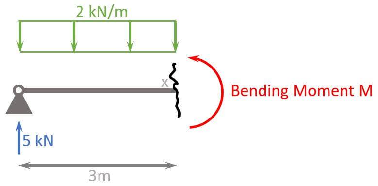
Now that we have 2 loads (5kN and 2kN/m) we also have to consider the load direction. ⬆️⬇️
First, we transfer the line load of 2 kN/m into a point load:
$$2 kN/m \cdot 3m = 6 kN$$
Second, we do moment equilibrium, which means that all moments in point x need to equal 0. Again, a moment is calculated by a point load $\cdot$ lever arm.
$$\sum M=0: 5 kN \cdot 3m – 6 kN \cdot 1.5m – M = 0$$
We solve this equation for M.
$$M = 5 kN \cdot 3m – 6 kN \cdot 1.5m = 15 kNm – 9 kNm = 6 kNm$$
Let’s look at a full calculation example. 👇👇
Calculation Example
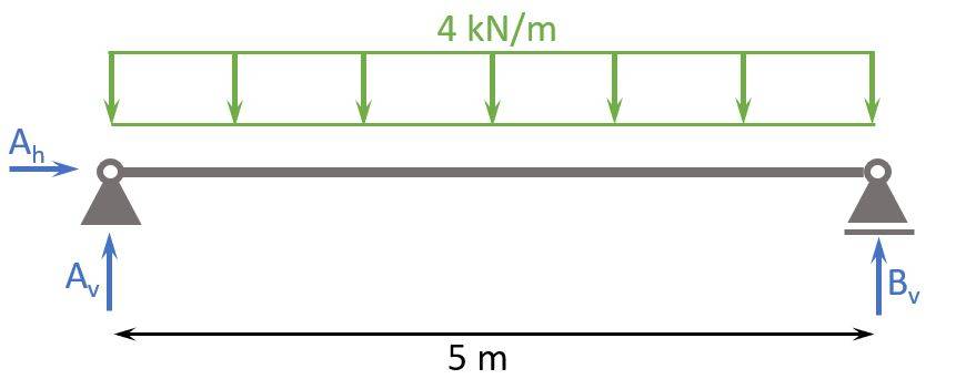
We now can calculate the bending moment of a simply supported beam which is subjected to a line load.
Here are the steps, we are going to follow to calculate the bending moments:
- Calculate the reaction forces Ah, Av and Bv
- Cut the beam at a location x
- Calculate the bending moment at location x
- Repeat 2. and 3. to calculate the moments at different locations
1. Calculation of the reaction forces
We use moment equilibrium in point b to calculate Av, because the support in point b is a hinge and therefore the moment = 0.
$$\sum M = 0: A_v \cdot 5m – 4 kN/m \cdot 5m \cdot \frac{5m}{2} + M = 0$$
As already said, M = 0 and therefore
$$A_v \cdot 5m = 4 kN/m \cdot 5m \cdot \frac{5m}{2}$$
$$A_v = 4 kN/m \cdot \frac{5m}{2} = 10 kN$$
We use vertical equilibrium to calculate Bv.
$$\sum V = 0: A_v + B_v – 4 kN/m \cdot 5m = 0$$
$$B_v = – A_v + 20 kN = 10 kN$$
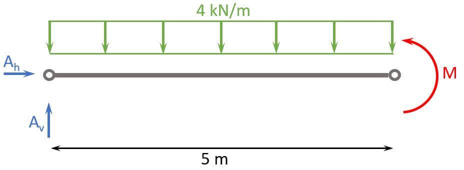
2. Cut the beam at a location x
Let’s make the first cut at x=3m.
3. Calculate the bending moment at location x
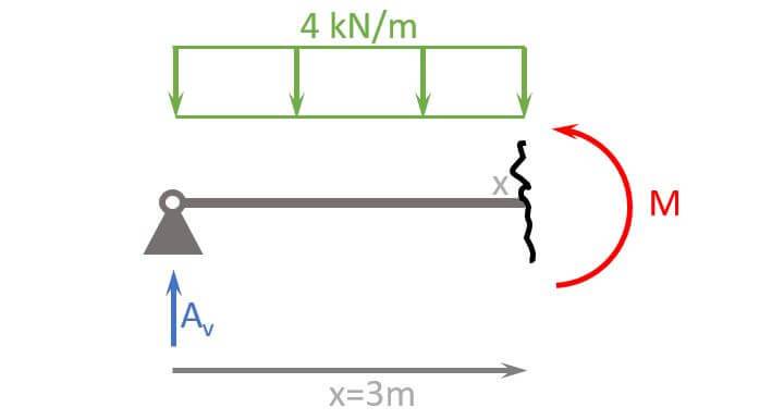
We use the moment equilibrium to calculate M at x=3m.
$$\sum M = 0: A_v \cdot 3m – 4 kN/m \cdot 3m \cdot \frac{3m}{2} – M = 0$$
$$M = 10 kN \cdot 3m – 4 kN/m \cdot 3m \cdot \frac{3m}{2} = 12 kNm$$
4. Calculate the moments at different locations
Alright, let’s also calculate the moment at x=2m and x = 4.5m.
x=2m
$$\sum M = 0: A_v \cdot 2m – 4 kN/m \cdot 2 m \cdot \frac{2m}{2} – M = 0$$
$$M = 10 kN \cdot 2m – 4 kN/m \cdot 2m \cdot \frac{2m}{2} = 12 kNm$$
x=4.5m
$$\sum M = 0: A_v \cdot 4.5m – 4 kN/m \cdot 4.5 m \cdot \frac{4.5m}{2} – M = 0$$
$$M = 10 kN \cdot 4.5m – 4 kN/m \cdot 4.5m \cdot \frac{4.5m}{2} = 4.5 kNm$$
Alright, we could continue and calculate the moments at other points as well, but I think you understood how it works.
Let’s move on and visualize the results. 🚀🚀
Bending Moment Diagrams
A great visualization of the calculated results is a bending moment diagram. The following diagram visualizes the bending moments of the example above.
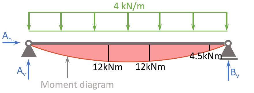
To create a bending moment diagram, we simply plot the values from the moment equation.
Don’t worry, you don’t have to do that manually later on. Software programs help us with that!
Bending Moment Formulas
For the most used static systems, there are luckily formulas that help us to calculate the bending moments. We covered them extensively in the following articles:
- Moment formulas of the simply supported beam
- Moment formulas of the cantilever beam
- Moment formulas of the 2-span continuous beam
So we’ll just mention the most important ones in this article.
Moment Of Simply Supported Beam Due To Line Load
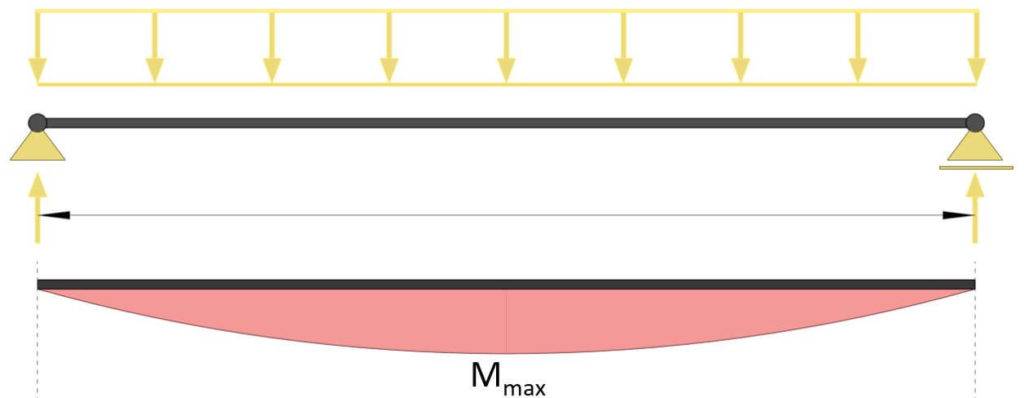
Max bending moment
$$M_{max} = \frac{1}{8} \cdot q \cdot l^2$$
Moment Of Simply Supported Beam Due To Point Load
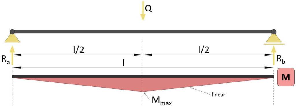
Max bending moment
$$M_{max} = \frac{1}{4} \cdot Q \cdot l$$
Moment Of Simply Supported Beam Due To 2 Point Loads
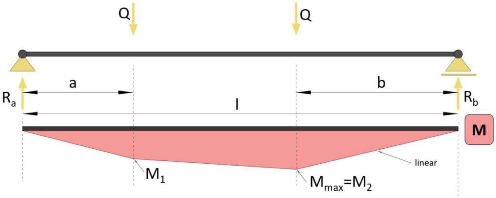
Max bending moment (if a<b)
$$M_{max} = \frac{Q}{l} \cdot (l – b + a) \cdot b$$
Moment Of Cantilever Beam Due To Line Load
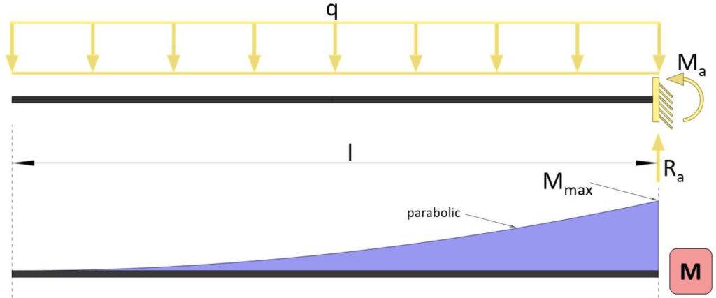
Max bending moment
$$M_{max} = -\frac{1}{2} \cdot q \cdot l^2$$
Moment Of Cantilever Beam Due To Point Load
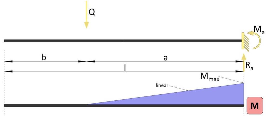
Max bending moment
$$M_{max} = -Q \cdot a$$
Moment Of Continuous Beam Due To Line Load
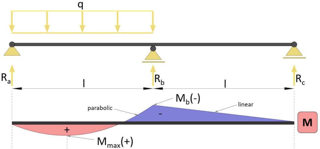
Max bending moment
$$M_{max} = -\frac{1}{16} \cdot q \dot l^2$$
Bending Moment In Real-World Applications
Now, let’s have a look at how bending moments are used in structural engineering projects.
Design of flat roof timber beams
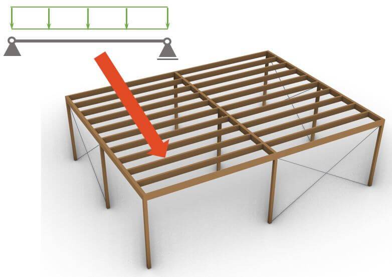
The timber beams that you can see in the picture above are calculated as a simply supported beam. External loads like snow, dead and wind load are applied to the beam and the bending moment is calculated to dimension the size of the timber beams.
We showed everything step-by-step in this article.
Design of steel beams
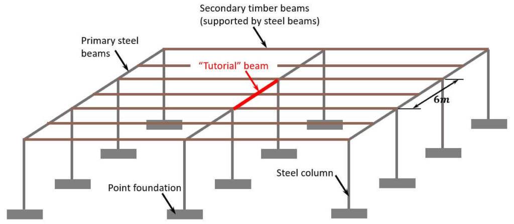
The steel beams in the picture above carry the loads of the timber beams. Due to those loads, the steel beams are subjected to bending moments which need to be resisted. We show in our steel beam design guide how to verify the bending moments.
Design of timber rafters
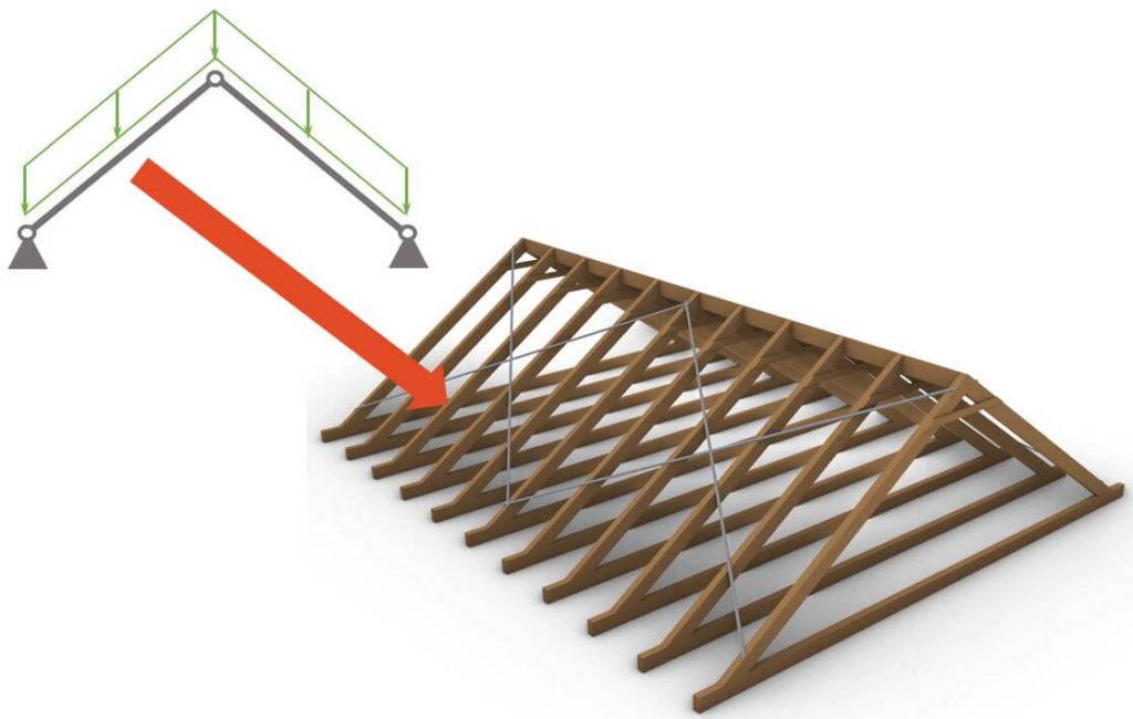
The rafters of the roof are exposed to the external loads such as wind, snow and dead load. This leads to bending moments in the rafters, and the bending capacity of the timber beams need to be bigger than the bending moments.
Check out our guide on how to design timber rafters to see exactly how to do it.
Conclusion
Now, that you got an understanding of bending moments, you can learn about how to use the bending moment to design structural elements such as
I hope that this article helped you understand the bending moment better and how to go further from here. In case you still have questions.
Let us know in the comments below. ✍️✍️
Bending Moment FAQ
A bending moment describes the internal force or moment that causes a beam, column, or any structural element to bend. If the moment resistance of a structural element is smaller than the bending moment that acts in an element, the structure will fail.
The bending moment at any point along a structural element can be calculated by multiplying the force applied to the beam by the perpendicular distance from the point of interest to the line of action of the force. The unit is kilonewton-meters (kNm) in Europe and foot-points (ft-lb) in the US.
Yes, there are many structural engineering software programs that can calculate the bending moments. For example: Dlubal RFEM, Autodesk Robot, Ftool, Polybeam, SOFiSTiK, FEM Design and many more.
– adding supports or bracing to decrease the span
– reducing the loads
![Arch – Moment And Normal Force Calculation Due To Line Load [A Guide]](https://www.structuralbasics.com/wp-content/uploads/2022/05/Arch-Structure-Internal-Force-Calculation-Due-To-Line-Load-768x439.jpg)
![The Pratt Truss Explained [2026]](https://www.structuralbasics.com/wp-content/uploads/2022/12/Pratt-truss-explained-768x439.jpg)
![Queen Post Trusses Explained! [2026]](https://www.structuralbasics.com/wp-content/uploads/2023/02/Queen-post-truss-768x439.jpg)