What Is A Normal Force? {2026}
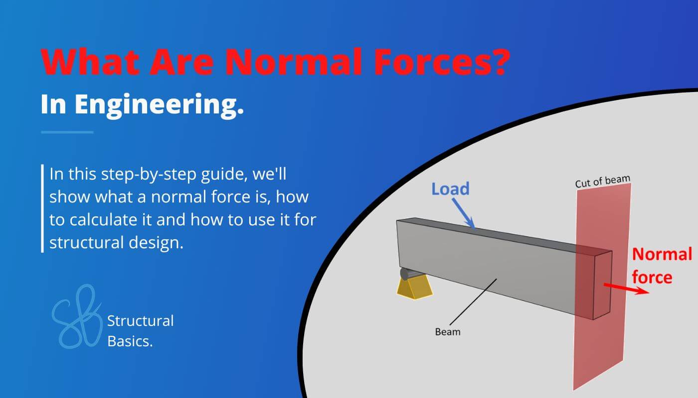
Normal forces in engineering refer to the internal axial forces that act perpendicular to the cross-section of a beam. A normal force leads to either compression or tension in a structural element, depending on its sign. ➕➖
By analysing the normal forces in beams, the dimensions of the structural elements are found. 🟫🟫
So in this blog post, we’ll explain what a normal force is step-by-step.👍👍
We’ll also add real-world examples, which you usually don’t see in uni. 👀👀
Alright, let’s get started. 🚀🚀
What Is The Normal Force?
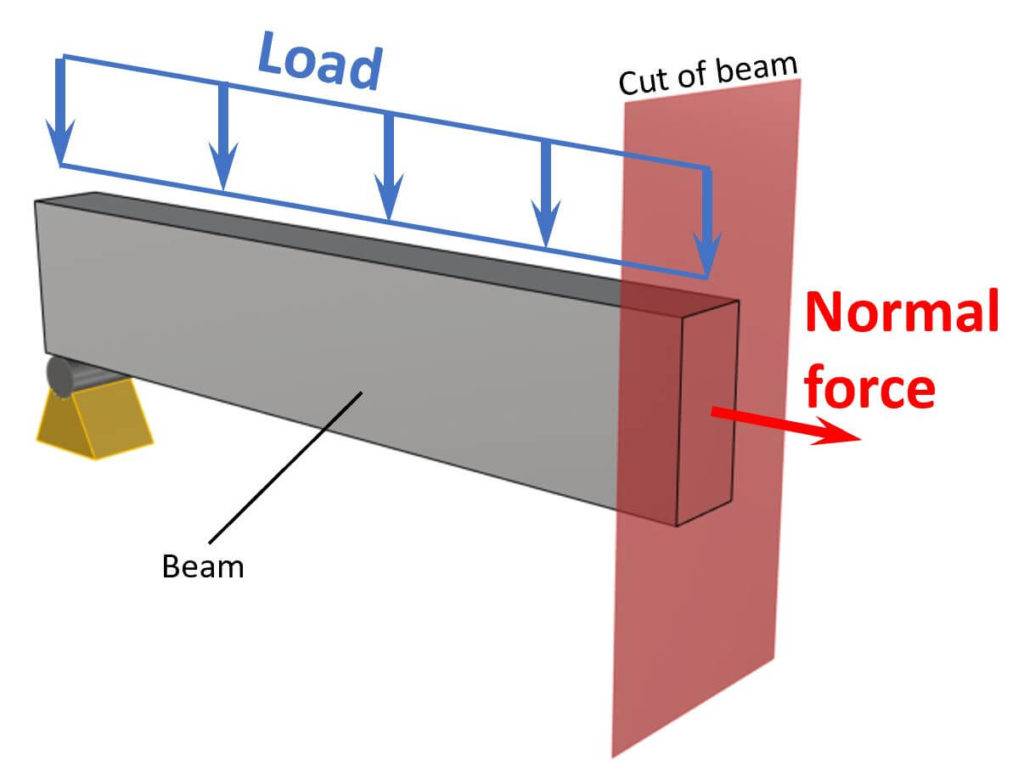
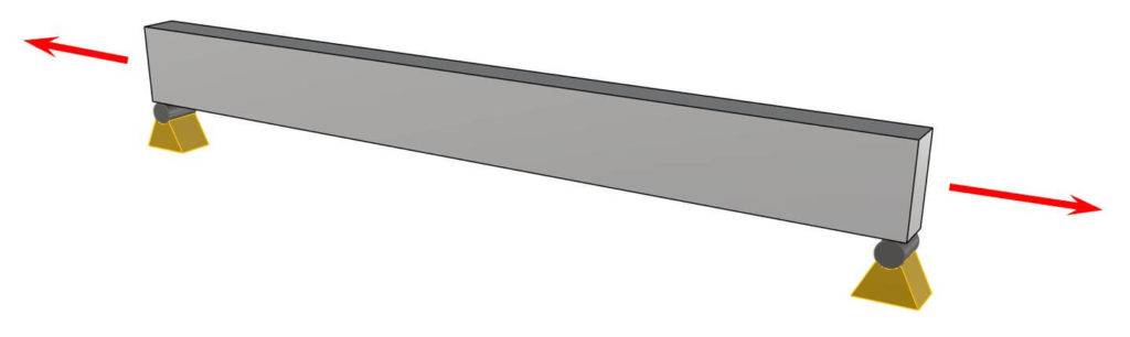
In structural analysis, the normal force is a type of internal force that acts perpendicular to the cross-section of a structural member, such as a beam (picture below), column, etc. It arises due to the external loads applied to the structure and the reactions developed at its supports.
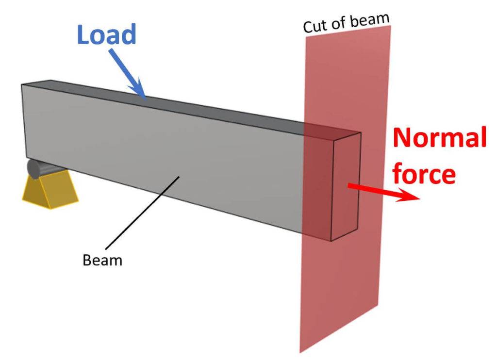
The normal force can also be called as axial force or compression/tension force, depending on whether the element (beam) is compressed or stretched.
Compression in beam
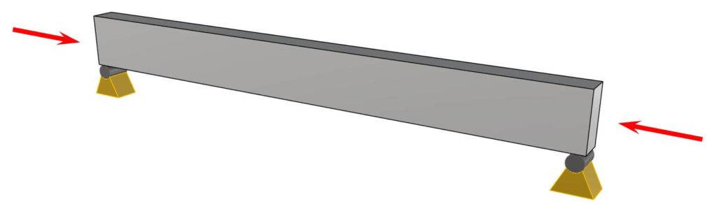
When the normal force is directed inward, towards the center of the member, it represents compressive force, while an outward-directed normal force represents tensile force.
Tension in beam
Now, let’s get a bit more technical.
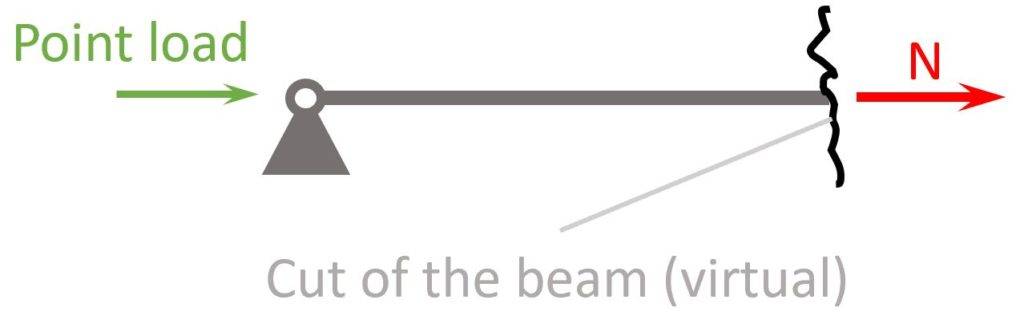
Normal forces appear at any location of the beam (if the beam is horizontally loaded), and it’s visualized as an arrow. ⬇️⬇️
As it appears at any point of the beam, we cut the beam. This is done to calculate the internal forces, such as normal and shear forces at the point of the cut.
Due to this normal force, the beam experiences a normal stress.
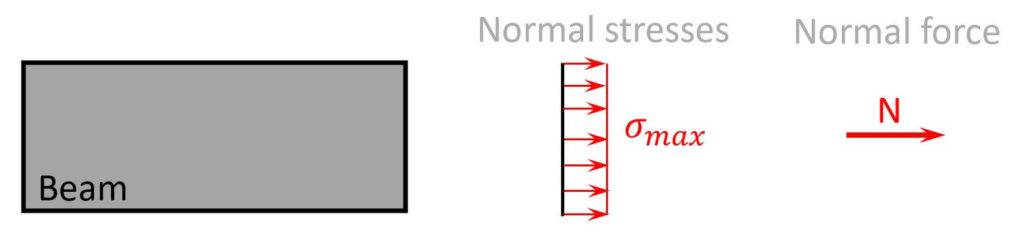
Btw, normal stresses also appear due to bending moments, which we have shown here.
In the picture above, you can also see that the biggest stresses appear in the centre of the cross-section.
The beam fails if
$$\sigma_{max} > \sigma_{resistance}$$
where $\sigma_{resistance}$ is the normal stress resistance of the beam/material. This stress resistance is found due to the material of the beam.
So for example, a steel beam S235 has a yield strength of 235 MPa, which is the stress resistance you use.
As you can imagine, the bigger the normal force, the bigger the normal stress.
But how does the normal force increase?
Well, we’ll calculate it in a second, but in general we can say that it increases due to increased
- loading
- span
- stiffness
Now, let’s have a look at how we determine the magnitude of a normal force. 👇👇
Normal Force Calculation
Normal forces are calculated as the sum of all forces in the direction of the normal force, or also called equilibrium. In our example beam, that is the horizontal direction, as it is the case for most beams.
$$\sum H = 0$$
Alright, let’s do that for an example. 👇👇
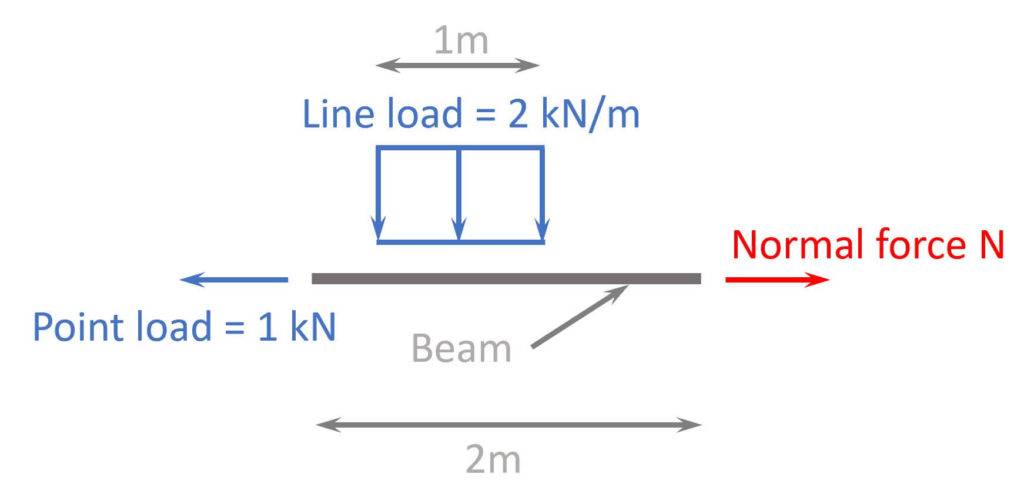
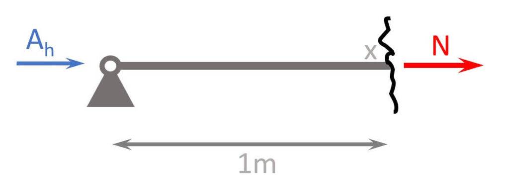
We define to the right ➡️➡️ as the positive direction ➕➕. But you could also pick to the left ⬅️⬅️ as the positive direction. The result will be the same.
$$\sum = 0: -1 kN + N = 0$$
Now let’s solve that for the unknown force N.
$$N = 1 kN$$
Normal forces can be calculated at any location of a beam. If the beam is 5 m long, then we could have calculated the normal force also at the locations 3.1 m or 4.5 m from one end. These are just two examples. But in our case where we only have 1 horizontal load (1 kN), the normal force has the same value at these locations.
This was just an example of a small part of a beam to get started.
We can now move on and look at a full calculation example of a beam. 👇👇
Calculation Example
We now can calculate the normal force of a simply supported beam which is subjected to an inclined point load.
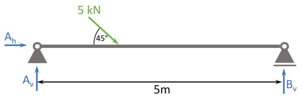
Here are the steps, we are going to follow to calculate the normal forces:
- Calculate the reaction force Ah
- Cut the beam at a location x
- Calculate the normal force at location x
- Repeat 2. and 3. to calculate N at different locations
1. Calculation of the reaction forces
We use horizontal equilibrium to calculate Ah.
First, we need to split up the inclined point load into a vertical and horizontal component.
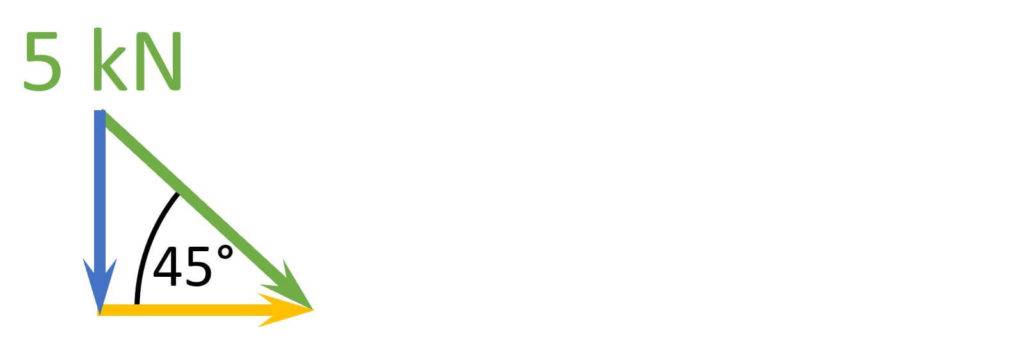
Horizontal component
$$cos(45°) = \frac{P_h}{5 kN}$$
$$P_h = 5 kN \cdot cos(45°) = 3.54 kN$$
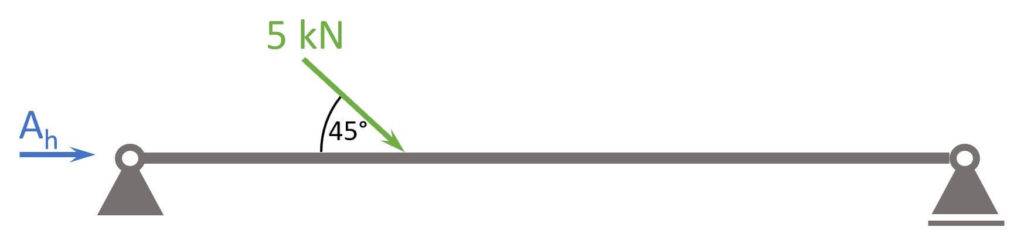
Now, let’s apply this load to the static system and calculate the reaction force $A_h$.
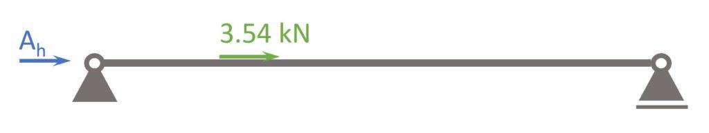
We use horizontal equilibrium to calculate the reaction force $A_h$.
$$\sum H = 0: A_h + 3.54 kN = 0$$
$$A_h = – 3.54 kN$$
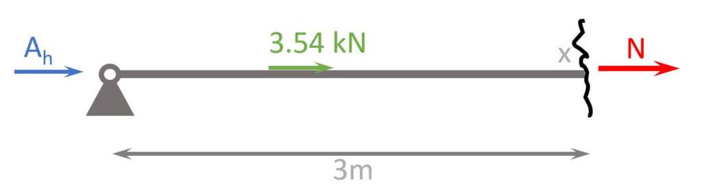
2. Cut the beam at a location x
Let’s make the first cut at x=1m, which is before the point load is applied.
3. Calculate the normal force at location x
We use the horizontal equilibrium to calculate N at x=1m.
$$\sum H = 0: A_h + N = 0$$
$$N = – A_v = 3.54 kN$$
Btw, a positive normal force means that the structural element (beam) acts in tension, while a negative force means compression.
In our case, the beam acts in tension.
4. Calculate the normal forces at different locations
Alright, let’s also calculate N at x=3m, which is after the point load is applied.
x=3m
$$\sum H = 0: A_h + 3.54 kN + N = 0$$
$$N = – A_v – 3.54 kN = 0 kN$$
Now, let’s move on and visualize the results. 🚀🚀
Normal Force Diagrams
A great visualization of the calculated results is a force diagram. The following diagram visualizes the normal forces of the example above.
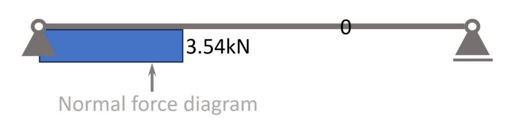
To create a diagram, we simply plot the values from the normal force equation.
Don’t worry, you don’t have to do that manually later on. Software programs help us with that!
Normal Force Examples
Now, let’s have a look at how normal forces are used in structural engineering projects.
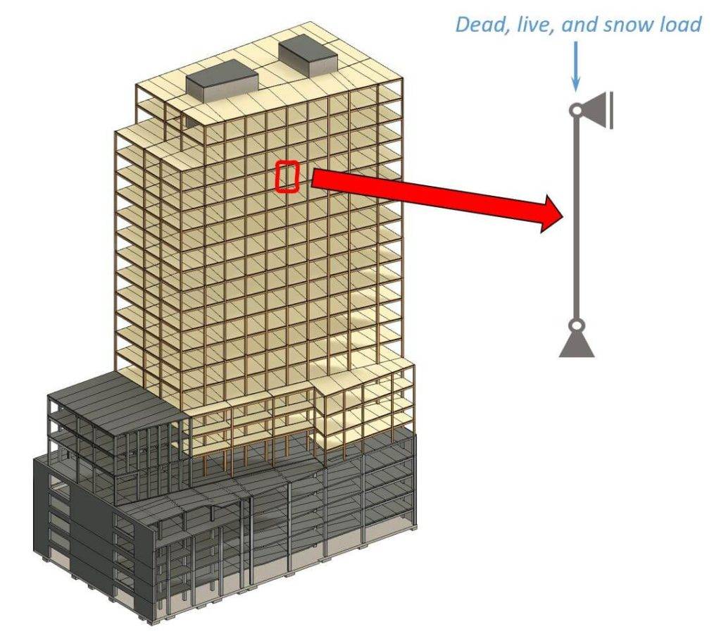
Design of steel columns
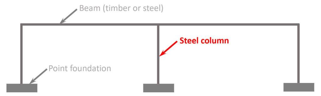
The steel columns that you can see in the picture above are calculated as a simply supported column or cantilever beam. External loads like snow, dead and wind load are applied to the roof beams and transferred to the columns. The vertical reaction forces of the roof beams are applied as vertical loads to the columns, leading to normal forces in the columns. The normal force is calculated to dimension the size of the steel columns or to verify that the columns don’t fail.
We showed everything step-by-step in this article.
Design of collar beams
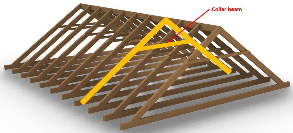
The collar beam (horizontal element) in the picture above is exposed to the normal forces – mostly compression forces. Due to this compression force, the collar beam is normal stresses and buckling.
We show the whole design in our collar beam guide.
Design of timber columns
The timber column from the picture above is calculated as a simply supported column or cantilever beam. External loads like snow, dead and snow load are applied to the roof and floor slabs and transferred to the columns. The vertical reaction forces of the floor beams are applied as vertical loads to the columns, leading to normal forces in the columns. The normal force is calculated to dimension the size of the timber column or to verify that the column don’t fail.
We showed everything step-by-step in this timber column guide.
Conclusion
Now, that you got an understanding of normal forces, you can learn about the other internal force – bending moment. Together, normal force and bending moment are used to design real structures such as
I hope that this article helped you, and you know how to go further from here. In case you still have questions.
Let us know in the comments below. ✍️✍️
Normal Force FAQ
Yes, in structural engineering, the terms “normal forces” and “axial forces” are the same. Both refer to forces acting along the longitudinal axis of a structural member (beam or column), in either compression or tension.
No, normal forces can act in any direction that is perpendicular to the cross-section of a structural element. In horizontal members such as beams, normal forces can be horizontal, while in inclined or vertical elements, they are vertical.
![Howe Truss [A Structural Guide]](https://www.structuralbasics.com/wp-content/uploads/2022/12/Howe-truss-768x439.jpg)