Torsion Verification of Reinforced Concrete (Eurocode)
Whenever you have a beam, strip footing, wall, etc. exposed to an excentric load, this element needs to be verified and designed for torsion.
Torsion is often neglected. Too often if you ask me.
Even in our bachelor and master courses, there is often not enough time to cover torsion.
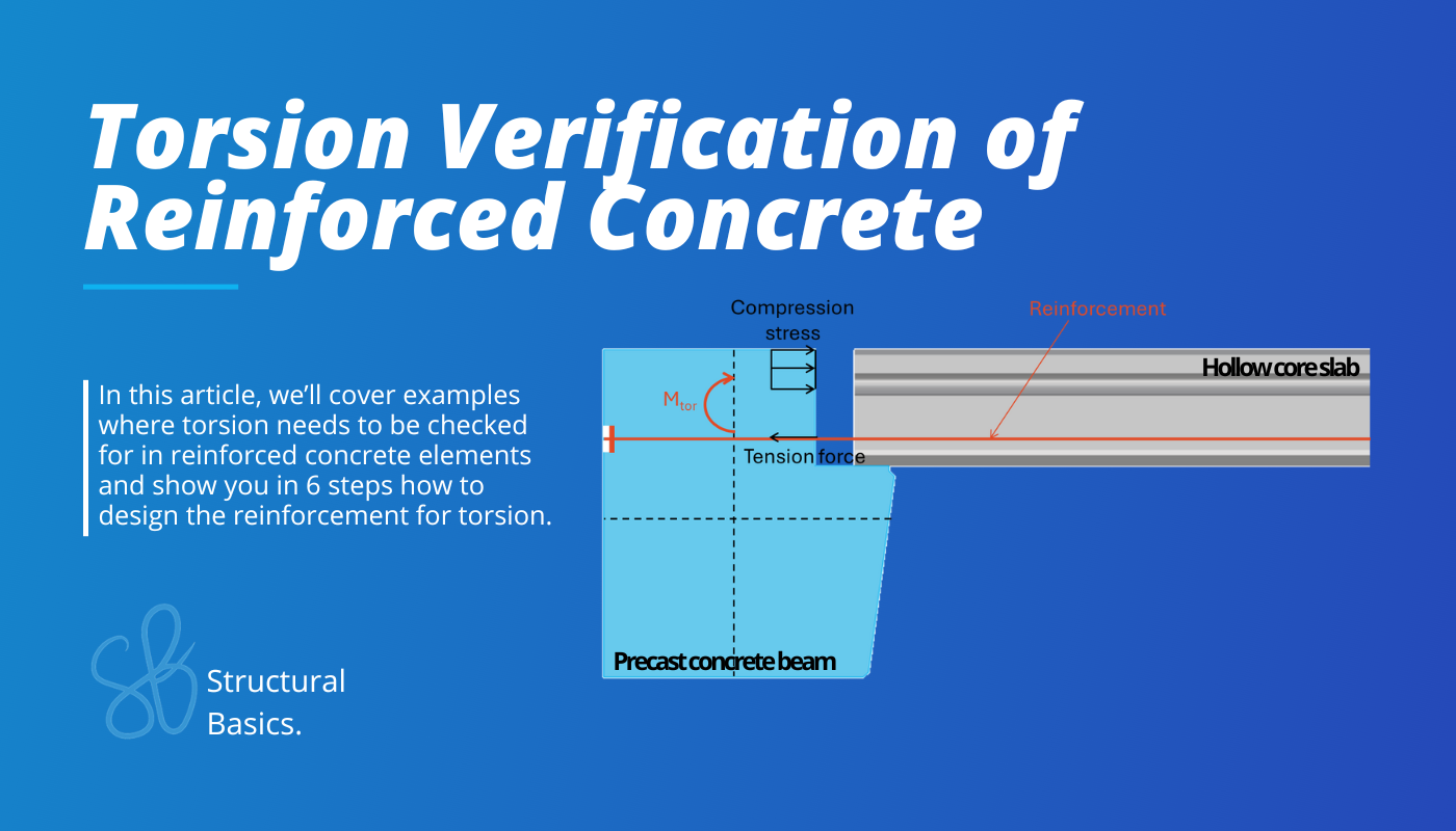
So in this article, we’ll cover examples where torsion needs to be checked for in reinforced concrete elements and show you in 6 steps how to design the reinforcement for torsion.
3 Examples of Torsion in Reinforced Concrete Elements
As always, there are plenty more examples of torsion. I picked the 3 cases that I worked with the most where torsion had to be checked.
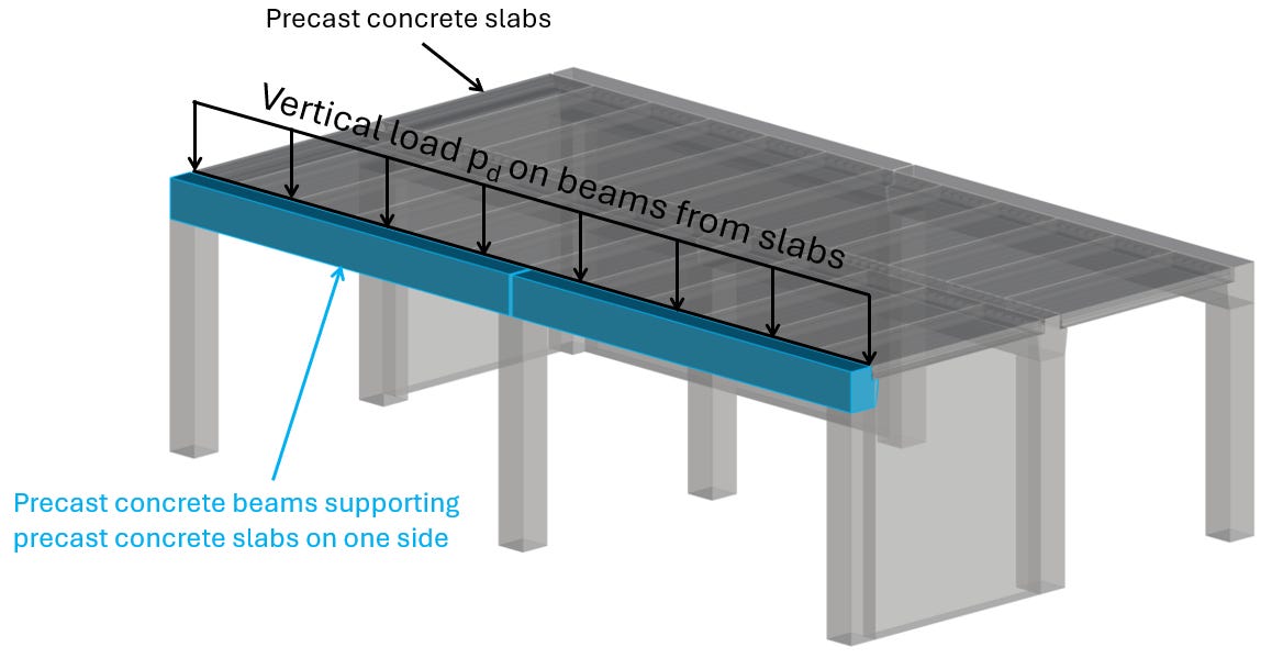
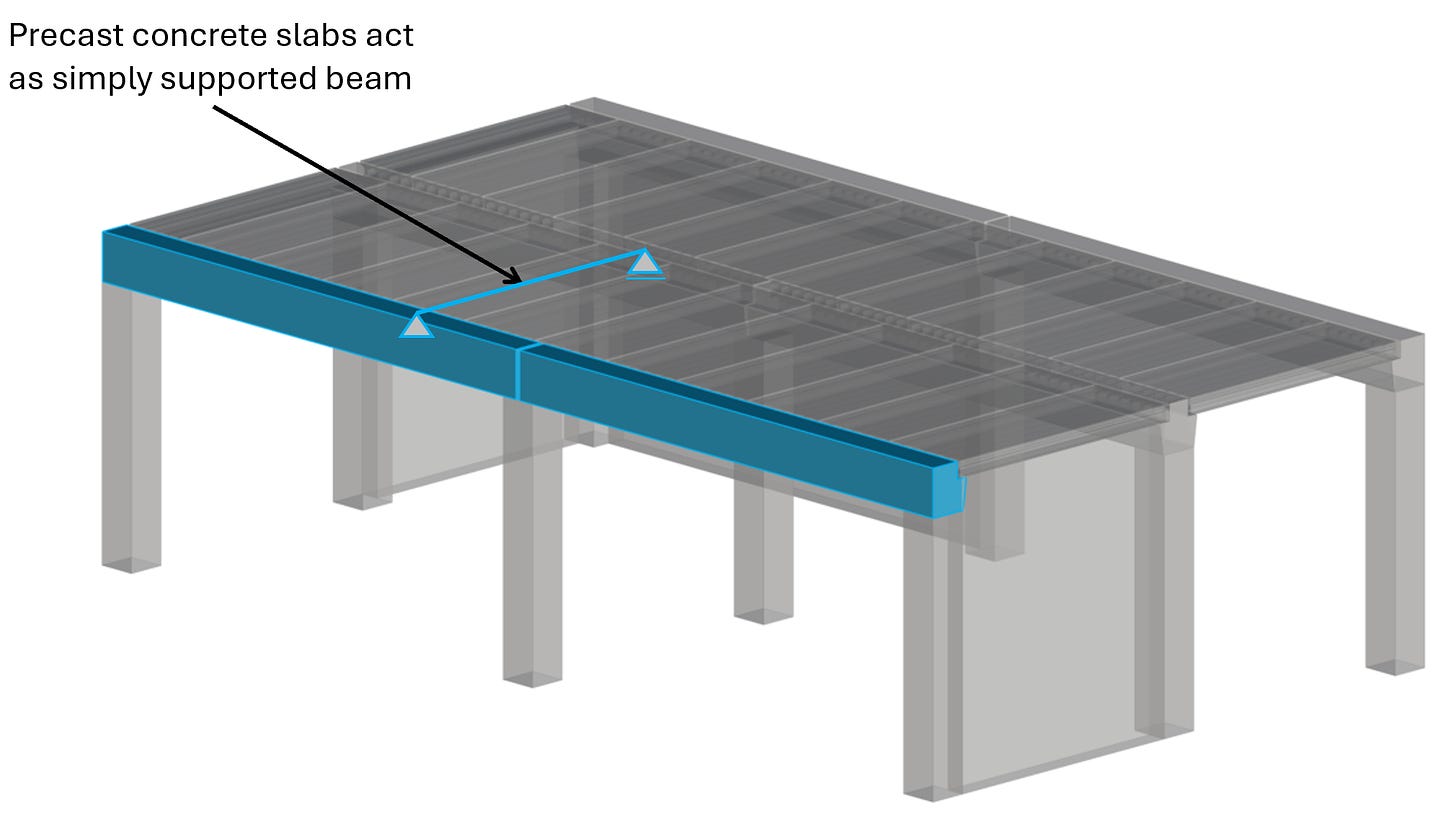
Example #1: Precast concrete beam supporting 1 precast slab
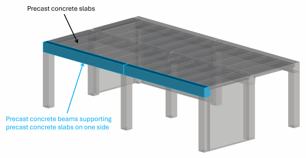
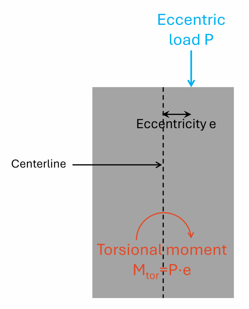
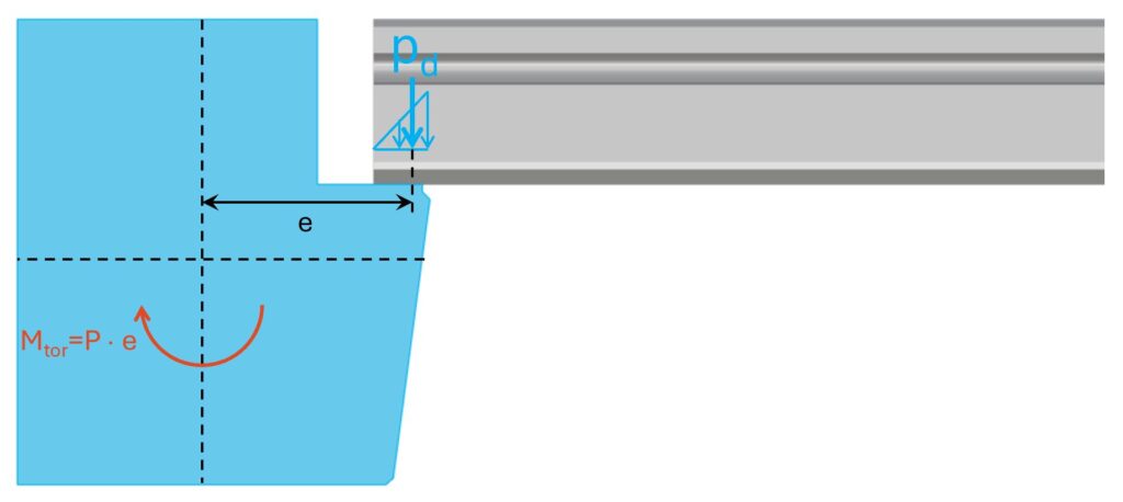
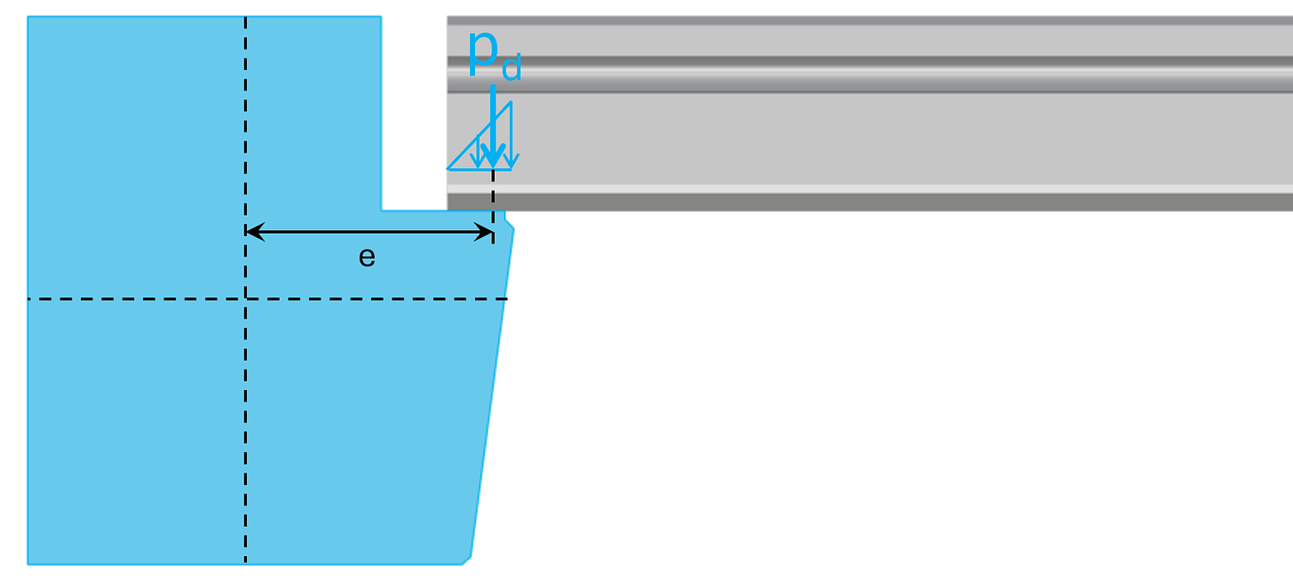
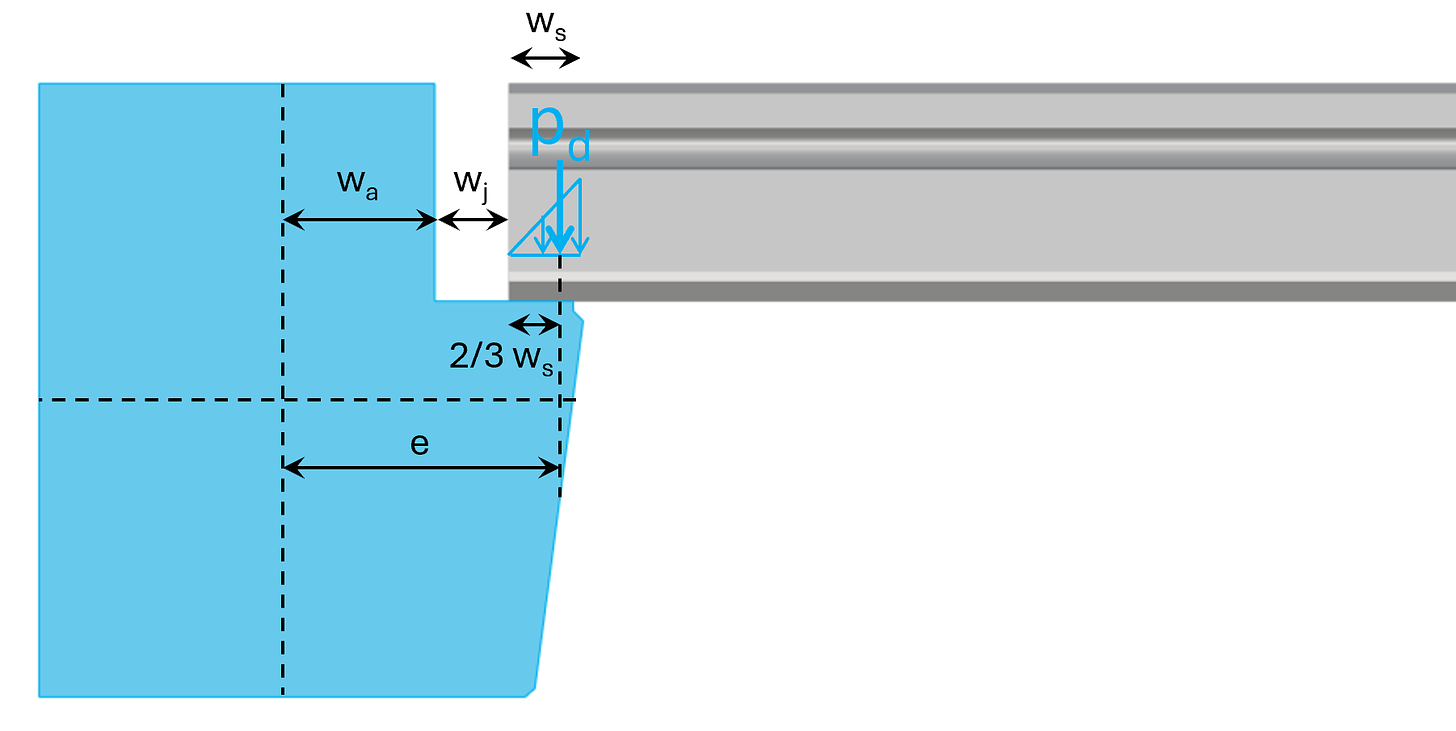
The precast concrete slabs are not supported in the center of gravity/centroid of the beams. Therefore, they transfer the vertical loads with an eccentricity of:
e = wa + wj +2/3 ws
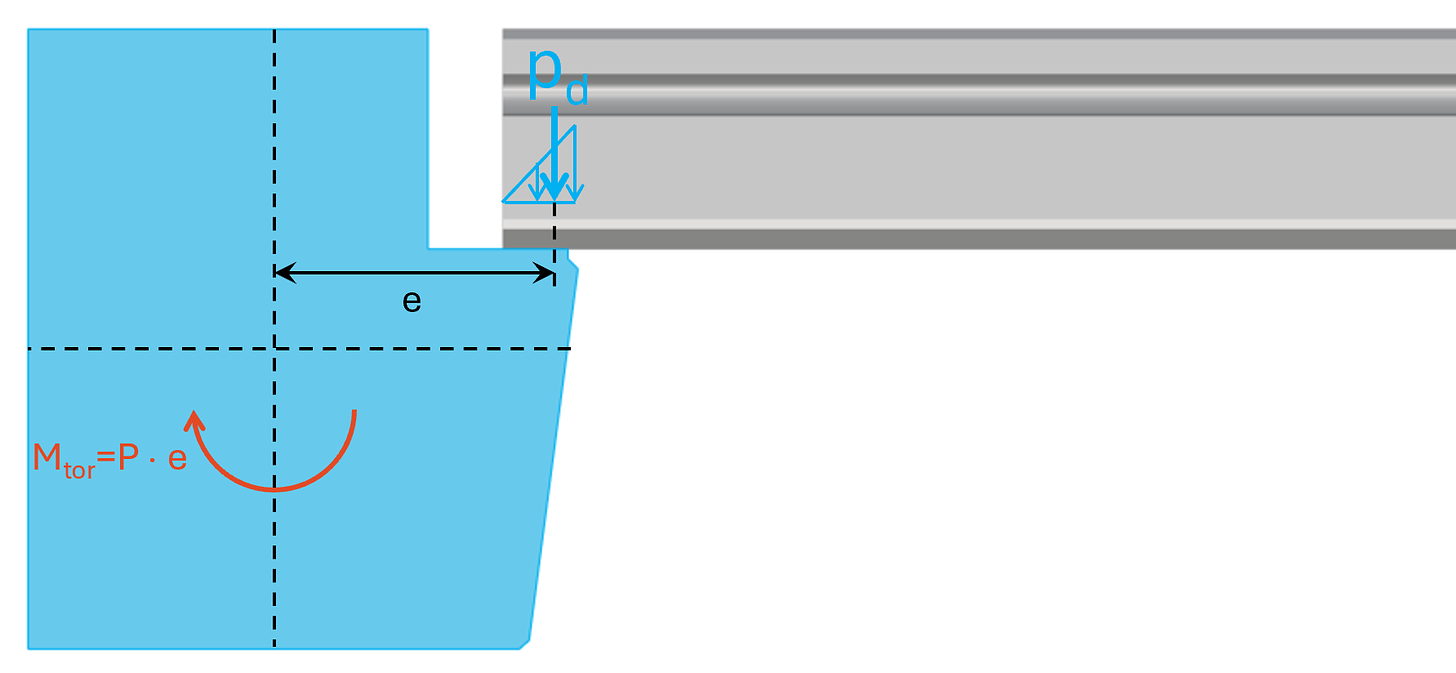
This eccentricity e leads to a torsional moment in the precast beam:
Mtor = P ⋅ e
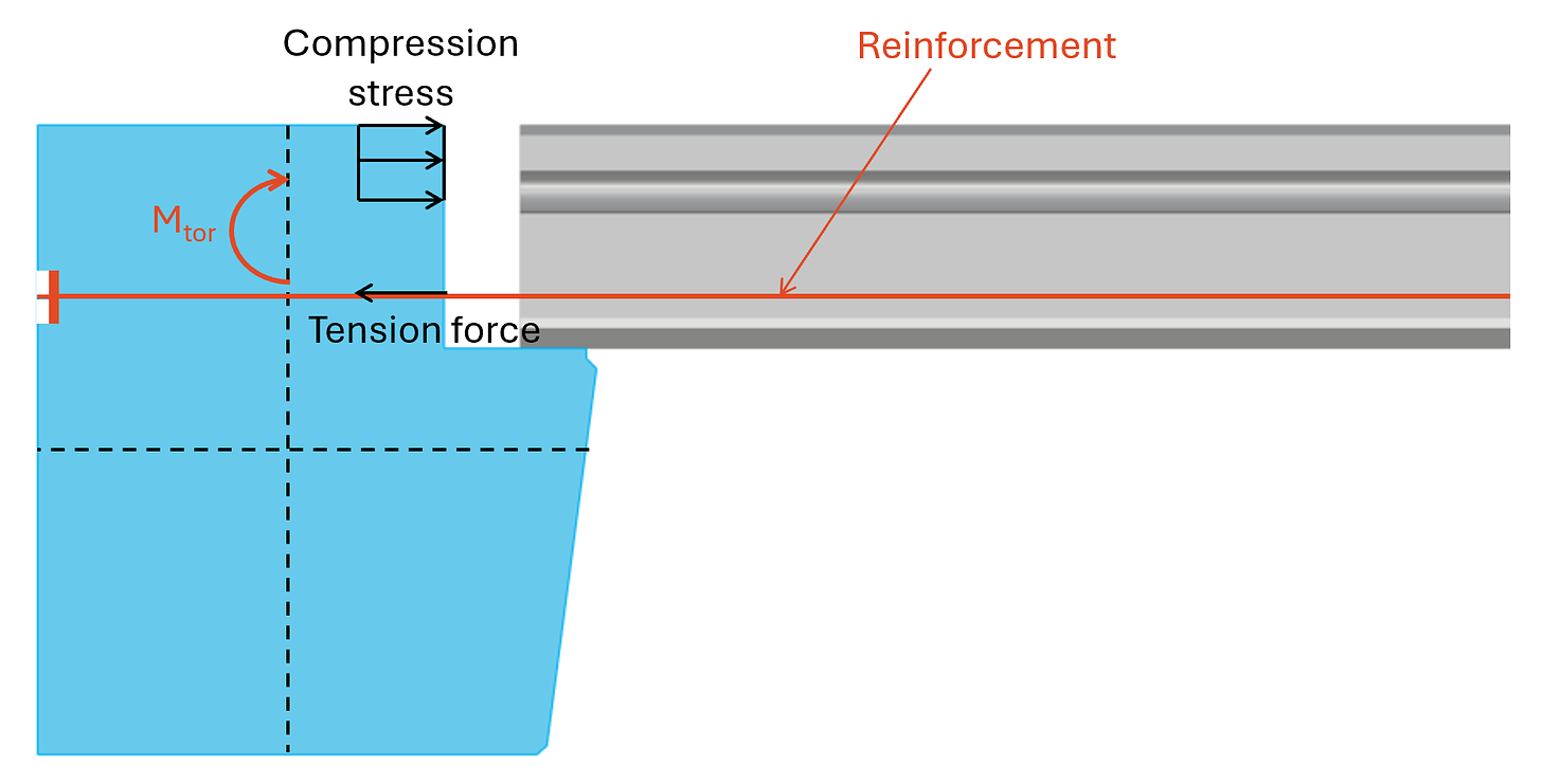
Now, this torsional moment is taken up by
- compression in the concrete at the top of the beam, joint and precast slab and
- tension in a reinforcement that is fixed/anchored to the beam.
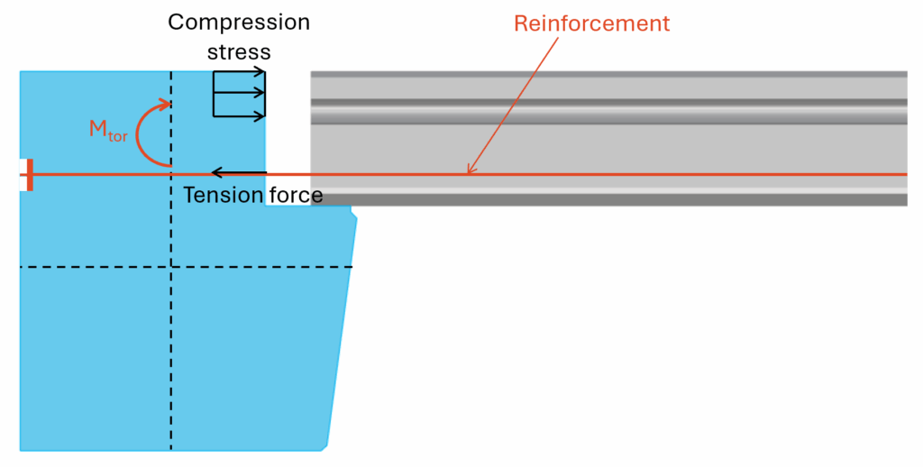
We’ll show the verification steps for concrete compression and tension of the reinforcement later in this article.
Example #2: Strip footing with excentric loading from wall
In many cases, the vertical load that is taken up by strip footings is not applied in its centerline. This can be due to many reasons. Here are a few:
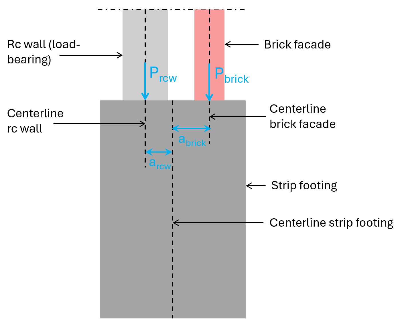
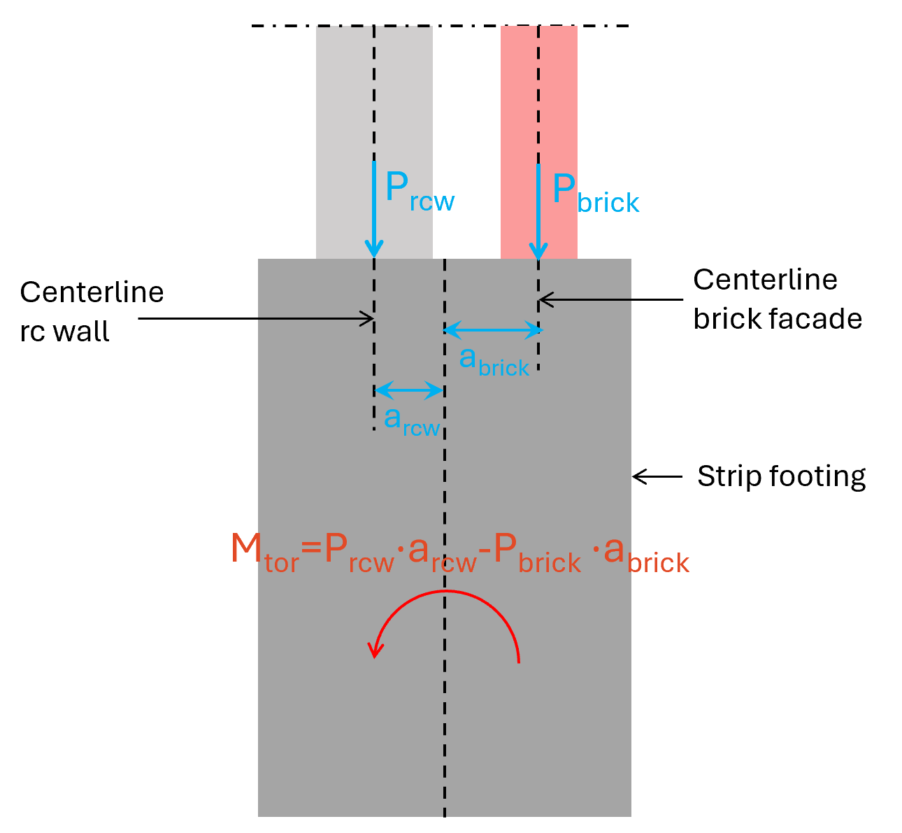
- Facade element consisting of load bearing wall and a brick facade is placed in the center of the strip footing. The load-bearing wall which takes up all vertical load is however placed excentric from the centerline of the strip (see image below).
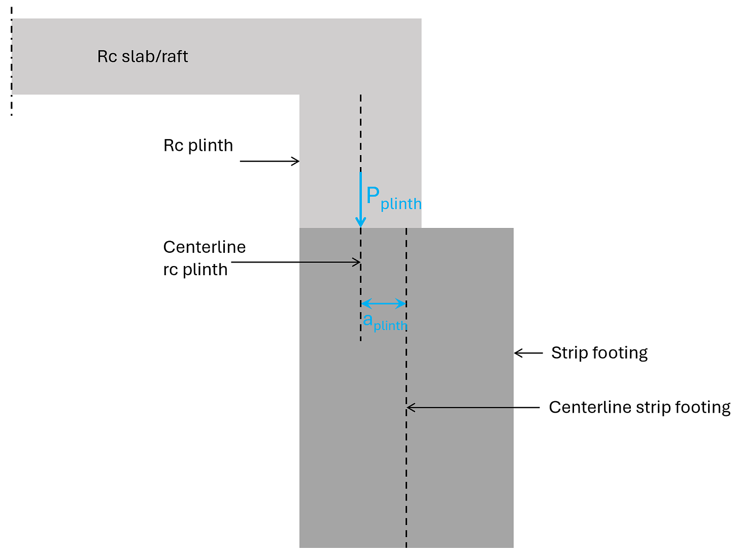
- Due to insulation reasons (and these days sustainability reasons) a plinth is used to connect the foundation plate/raft with the strip footing.
- Or simply if a column or wall wasn’t placed correctly in the execution. We should always include some tolerances in our design verifications.
Statically speaking these eccentricities are not ideal, because the eccentricity leads to torsion in the strip and/or a bending moment at the bottom of the strip which needs to be accounted for in the verification of the soil.
Little spoiler alert: Already small bending moments lead to quite a big reduction of the capacity of the soil.
We’ll show later how to design a reinforced concrete section for a torsional moment.
Example #3: Precast concrete floor diaphragm with 3 walls exposed to horizontal wind loading
The horizontal loads from wind and seismic load and earth pressure travel from the facades to the floor diaphragms, which then transfer these horizontal loads to the stabilizing elements such as shear walls.
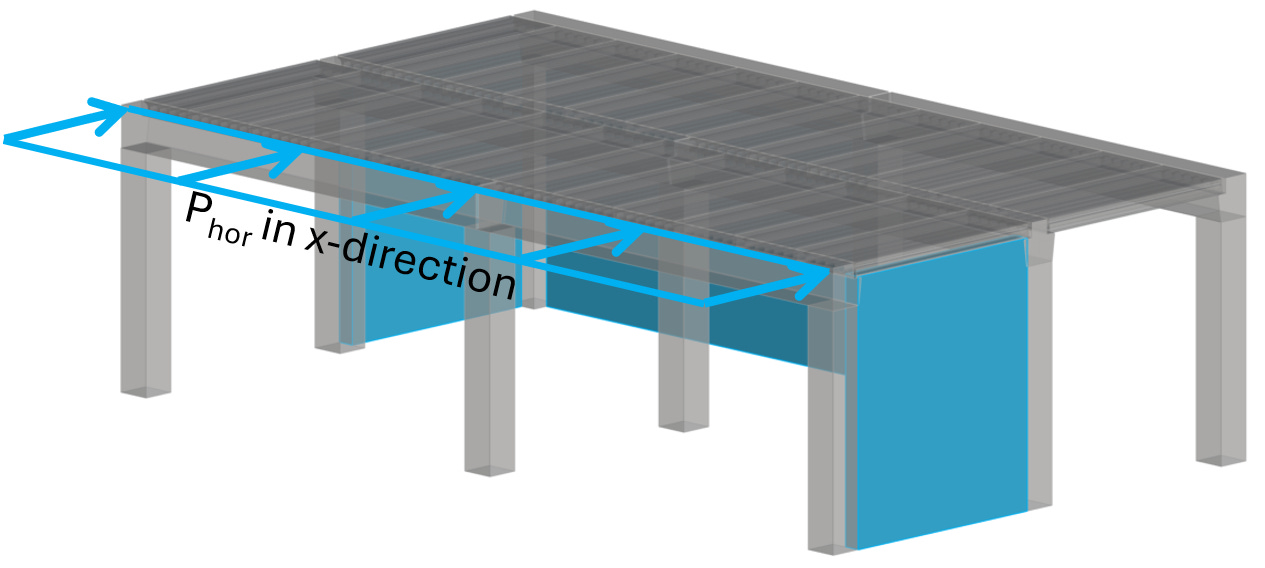
What is sometimes forgotten (for a good reason if you have in-situ concrete floors) is that the floor diaphragms need to resist these horizontal loads.
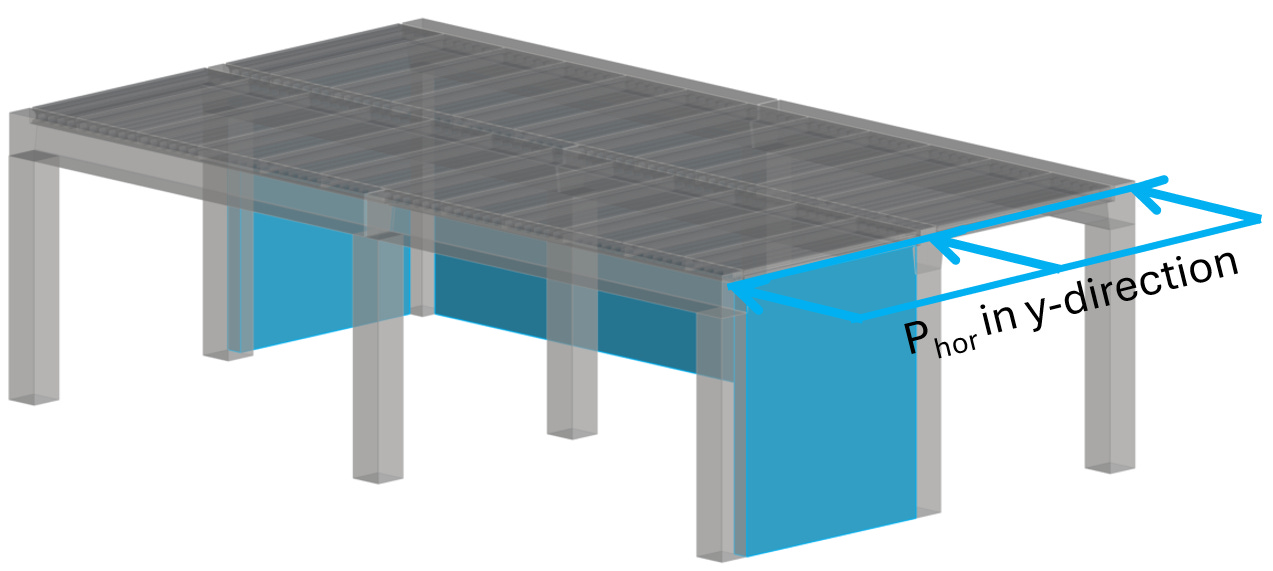
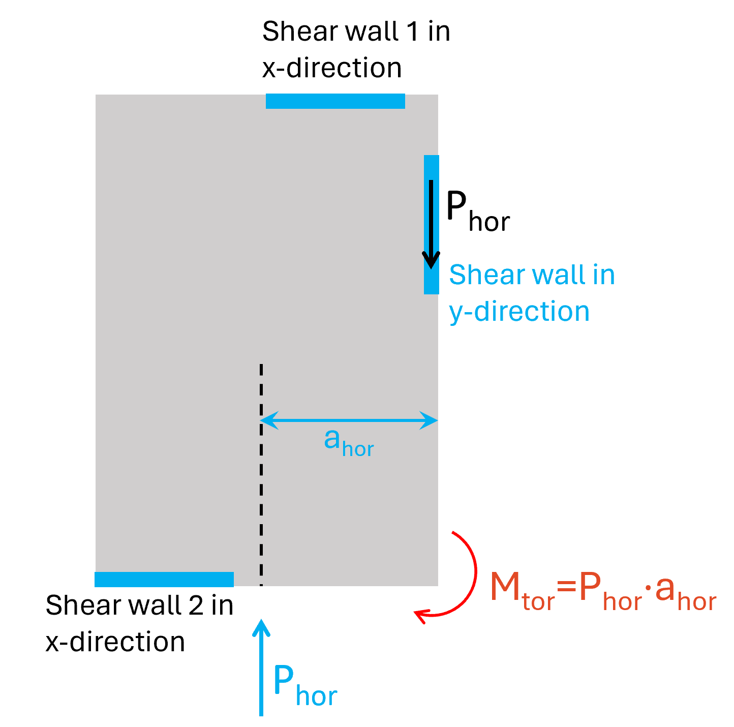
In the following, we’ll look at a floor diaphragm which needs to resist a torsional moment. This floor diaphragm can be simplified as a simply supported beam in x-direction. The 2 shear walls acts as the supports. But now the tricky part – in the y-direction it acts more like a cantilever beam with a torsional moment because we only have 1 wall in that direction.
Let me explain.
In y-direction, the load Phor needs to be taken up by the wall in y-direction.
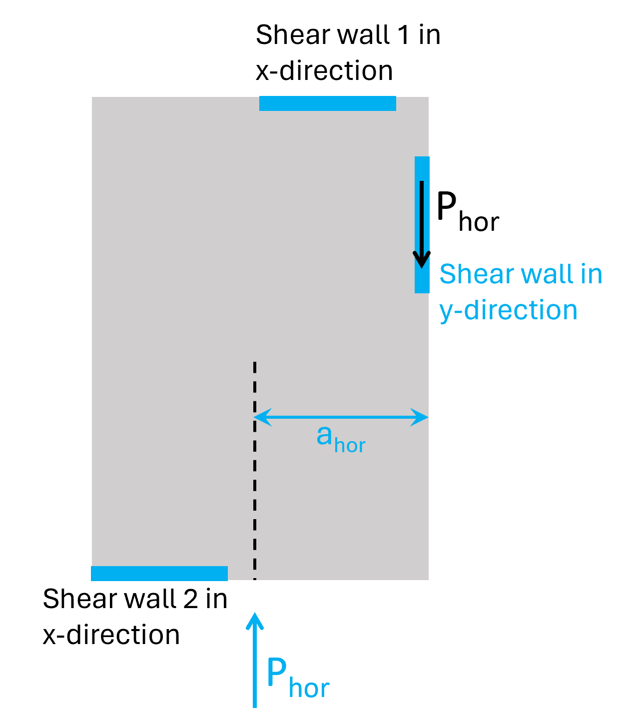
But because the shear wall is placed excentric to the load (→ ahor) the diaphragm is exposed to a torsional moment. We calculate the torsional moment for the bottom right corner.
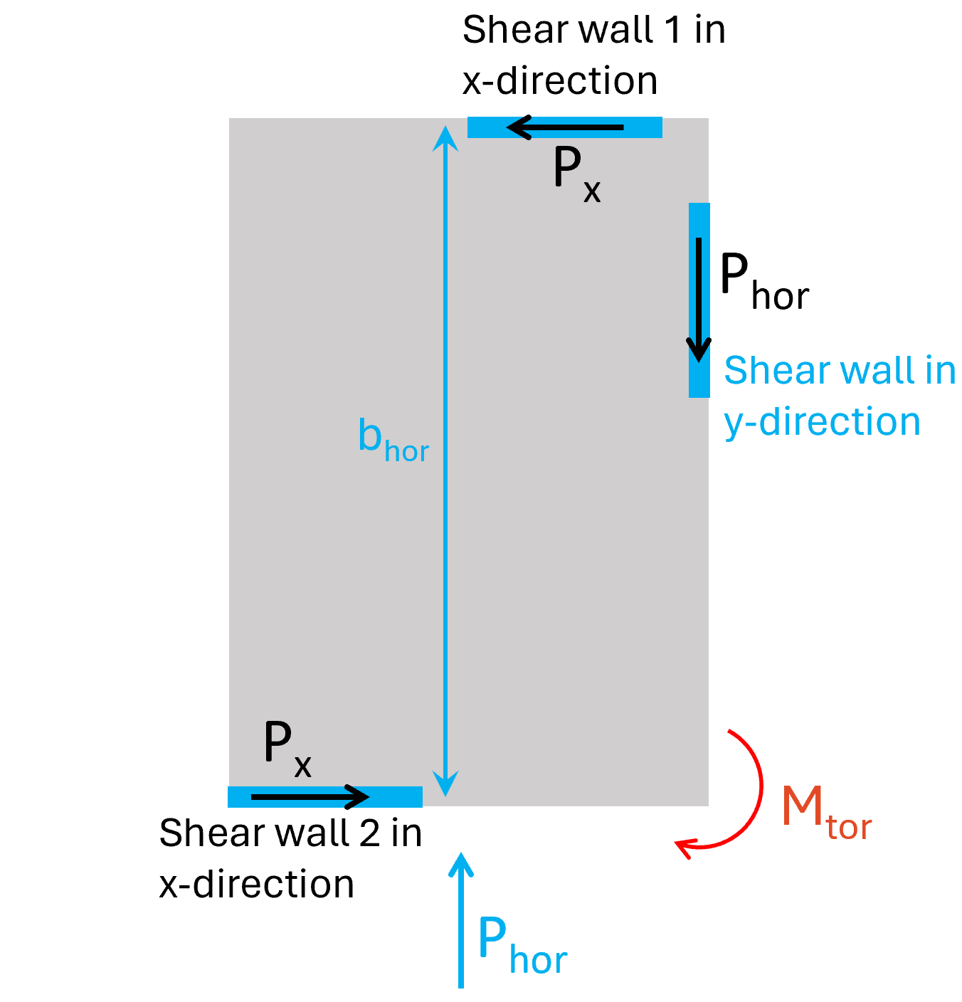
The 2 shear walls in x-direction then take up the torsional moment Mtor:
Px = Mtor / bhor
The torsional moment Mtor leads to shear forces in the diaphragm in y- and x-direction, which it needs to be verified for. But reinforced in-situ concrete slabs have quite a big shear capacity compared to the shear forces. That’s these diaphragms are often not verified. However, this gets critical for precast concrete floors with joint reinforcement, timber floors and trapezoidal sheeting if they are used as diaphragms.
If you didn’t understand everything, don’t worry, it took me a very long time to understand diaphragms. There are many different methods to verify them, and we’ll dive deeper in a future newsletter.
Torsion verification of reinforced concrete in 6 steps
In this article, we’ll use example #1 to explain the verification steps of torsion in rc elements.
We have already gone through some of the steps earlier. Nevertheless, we’ll document them here, as we always have to go through these steps in the torsion calculation.
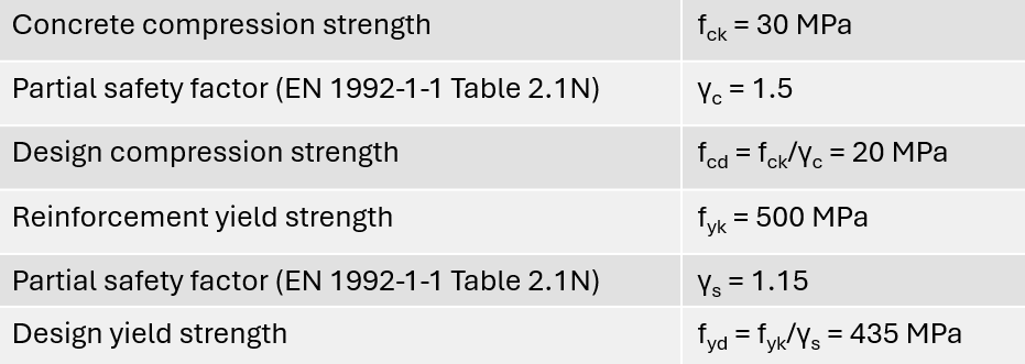
Step #1: Define the properties of concrete and reinforcement
Here are the concrete and reinforcement properties we use in this tutorial.
Step #2: Calculate the vertical loads
We won’t show how to calculate the loads in this newsletter, as each calculation of the individual load is an article for itself.
If you need to learn how to calculate loads according to Eurocode then I recommend to check out my book.
Module #1: Loads on a Residential Building teaches you everything you need to know about load calculation of buildings.
We’ll simplify this step and define the design area load on the precast concrete slabs as:
pd = 7 kN/m2
The design area load is calculated from characteristic loads and load combinations. (check out our previous articles if you are unfamiliar with characteristic loads and load combinations).
The precast concrete slab span as simply supported “beams” from beam to beam. The span is:
s = 7m
This leads to a load/ reaction force on the beam of:
rd = pd ⋅ s/2 = 24.5 kN/m
Step #3: Calculate the eccentricity and the torsional moment
First, we need to know the location of the centroid. This is not an article about how to calculate the centroid of a cross-section, but you can read up on it → here ←.
For complex cross-sections like this one, I like to use Rhino / Grasshopper with the “Area Moments” component. This component finds the centroid, and then we can measure the distance to the edge in Rhino.
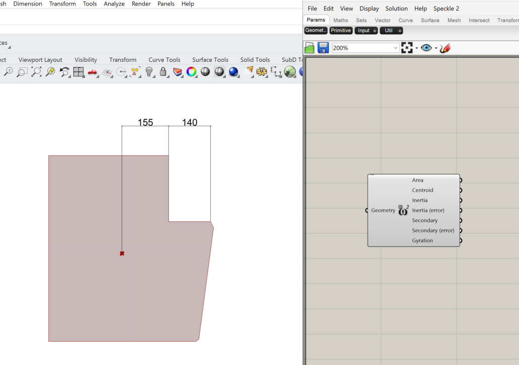
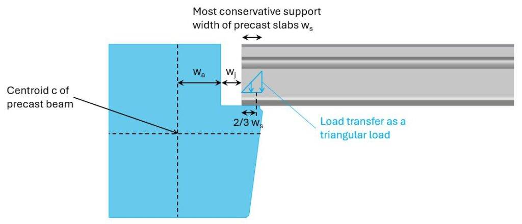
We then find the parameters of the next image.
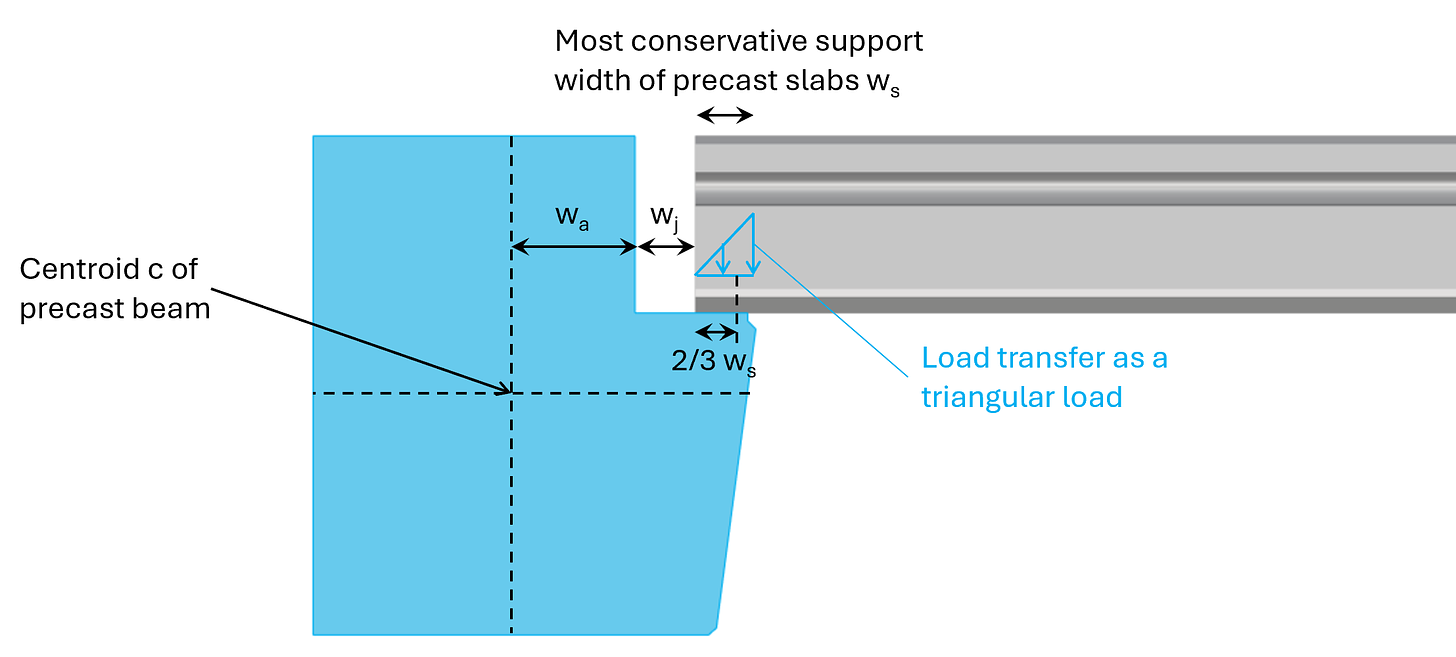
The support width of precast slabs depends on its height and probably also the country you design the building in. In Denmark, ws was conservatively taken as 65 mm for slabs of thickness 220 mm.
ws = 65mm
We then calculate the eccentricity e as:
e = 155mm + 140mm − 1/3 ⋅ 65mm = 273mm
Next, we’ll calculate the torsional moment per meter from the eccentricity as:
Mtor = rd ⋅ e ⋅ 1m = 6.7 kNm
Step #4: Calculate the pair of forces – compression stress and tension
The torsional moment is taken up by a pair of forces, which is a
- compression zone/stress in the top of the beam / joint / precast slab and
- a tension force in the reinforcement anchored to the beam and precast slab closer to the bottom fibre of the precast slab.
We decide the length of the compression zone to be 60 mm. The rebar is placed 80mm from the bottom of the precast slab.
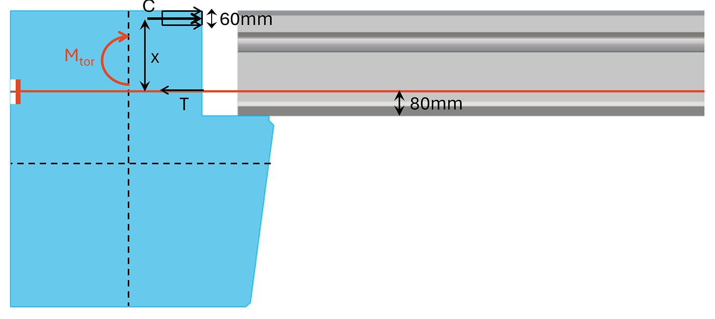
The distance x between the pair of forces is calculated as:
x = 220mm – 60mm/2 – 80mm = 110mm
C and T are calculated as:
C = T = Mtor/x = 60.9 kN
Step #5: Verify concrete compression
We calculate the compression stress (per meter) that acts in the compression zone as:
c = C/(60mm ⋅ 1m) = 1.01 MPa
Comparing that with the design compression strength leads to a utilization of:
η = c/fcd = 5.1% < 100% → OK!
Step #6: Verify the reinforcement
First, let’s calculate the tensile strength of the rebar. We use diameter 16mm, which has a cross-sectional area of:
As = π ⋅ (16mm/2)2 = 201mm2
This leads to a tensile capacity of:
TRd = As ⋅ fyd = 87.5 kN
The utilization of the rebar is therefore:
η = T/TRd = 69% < 100% → OK!
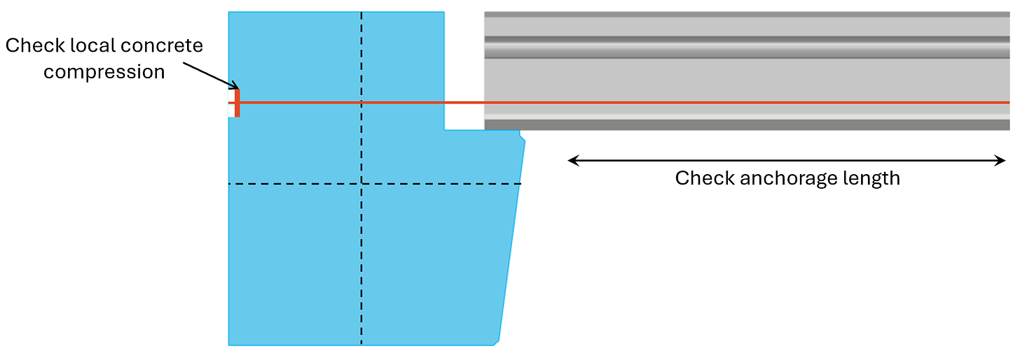
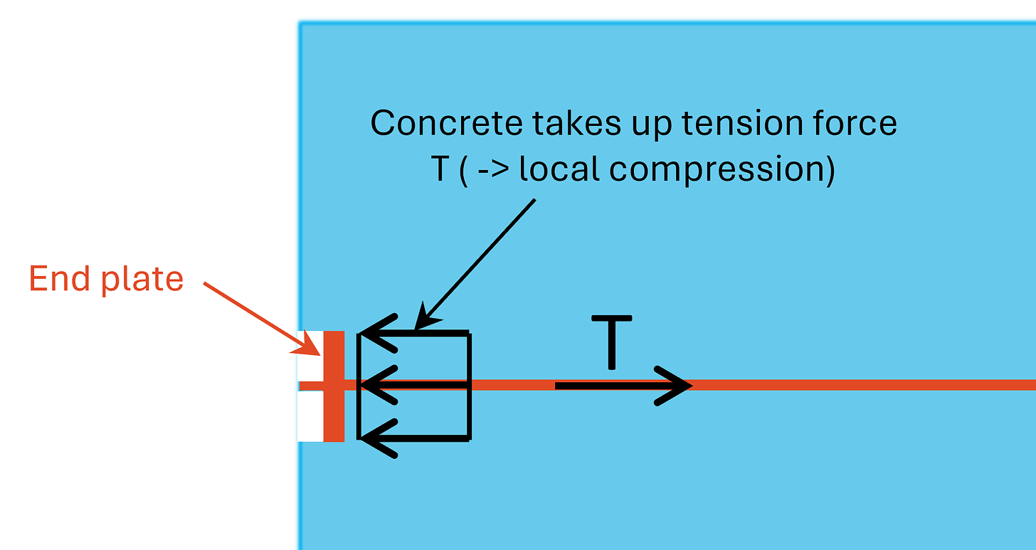
Now, there is one verification missing –
We need to make sure, the reinforcement is anchored correctly to both the precast slabs and to the beam. In the slab we need to make sure the anchorage length is fulfilled and because we can’t fulfill the anchorage length in the beam (it’s not wide enough), we add an end plate which transfers the tension load as compression to the concrete.
I just want you to be aware of this. Many engineers don’t care enough about these small details. But we all here reading this care .. because we are great engineers.
Final words
Once again, a “super-in-depth” guide. Hope you got value from it and understood the concept of torsion in reinforced concrete elements.
If you don’t want to miss any new structural design tutorials, then subscribe to our free weekly newsletter.
Or subscribe to my YouTube channel for regular updates.
Let’s design better structures together,
Laurin.

Laurin Ernst
![Pad Foundation In Clay [Design Of Soil And Concrete]](https://www.structuralbasics.com/wp-content/uploads/2023/05/Pad-foundation-design-clay-768x439.jpg)
![5 Timber Roof Structures Explained! [2026]](https://www.structuralbasics.com/wp-content/uploads/2022/01/Timber-roof-structures-768x439.jpg)
![Reinforced Concrete Column Design [2026]](https://www.structuralbasics.com/wp-content/uploads/2024/02/RC-column-design-768x439.jpg)