Reinforced Concrete T-Beam Design (Eurocode 2)
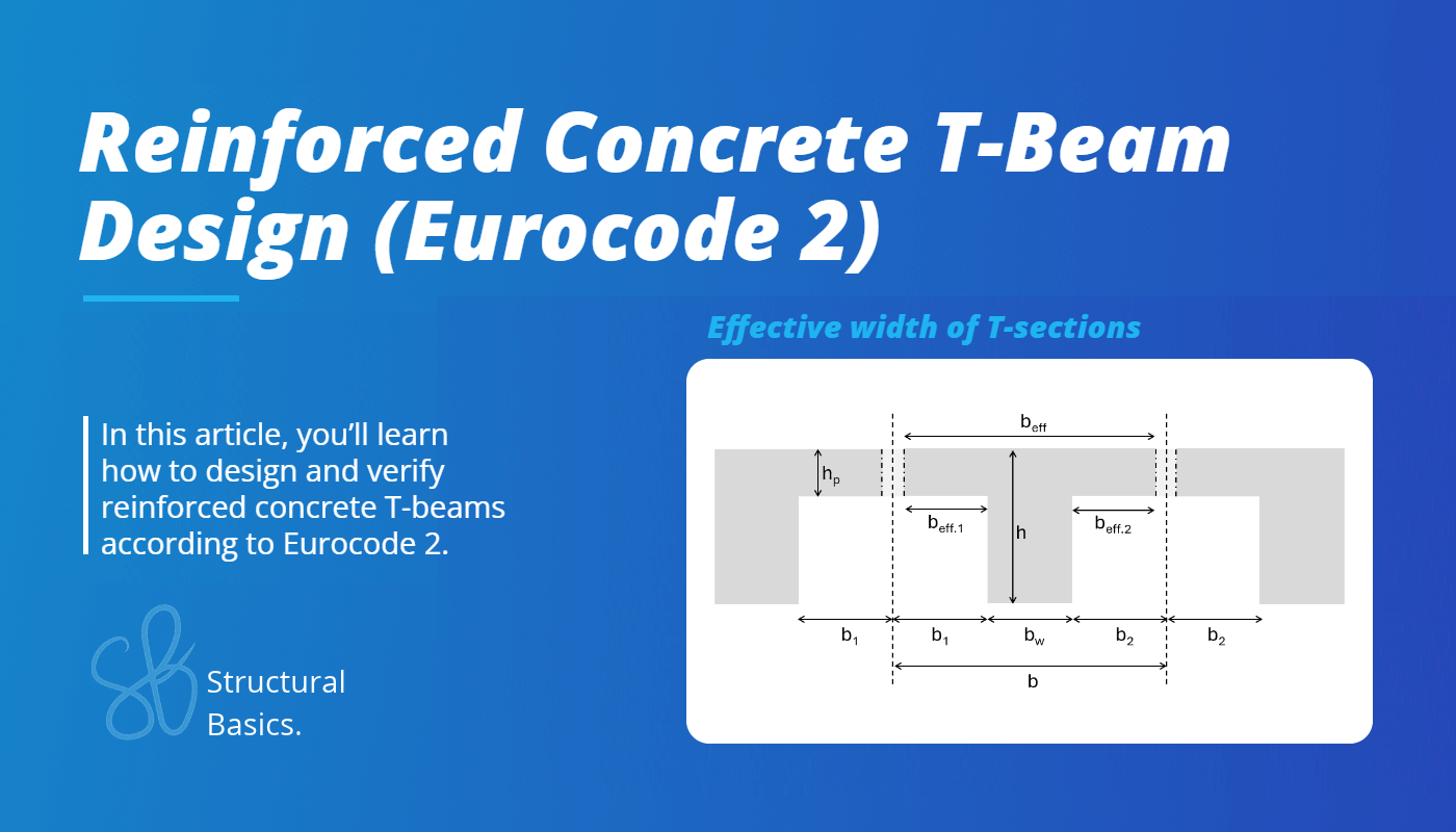
In this article, you’ll learn what reinforced concrete T- and L-beams are and how to design and verify them according to Eurocode 2.
T- and L-beams are a great way to increase the spans of reinforced concrete slabs without using walls as supports.
But first, what are T- and L-beams?
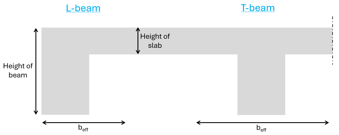
T- and L-sections, also called flanged beams, are beams that are integrated in the slab. That way, we save the height of the slab, but we can still use the distance from the lowest edge of the beam to the top edge of the slab as the height of the beam in our calculations.
And you’ll see later that we can use an extra width of the slab for the compression or tension zone. We call this the effective width.
In this article, we’ll run through the whole design of a T-beam:
- How to calculate the effective width of a T-section
- How to verify the T-beam for bending and design the longitudinal reinforcement
- How to check that the compression zone lies in the flange and verify the minimum reinforcement
Now, let’s get into it.
Process of reinforced concrete T-beam design
You’ll see that the verification of T- and L-beams is very similar to the one of rectangular beams. The only difference is that we work with an effective width.
Here’s an overview of the steps to design a reinforced concrete T-beam:
1. Calculate the characteristic and design loads that act on the beam
2. Define the properties of concrete and reinforcement
3. Calculate the effective width of the T-section
4. ULS bending verification
5. ULS shear verification
6. SLS crack verification
7. SLS deflection verification
You don’t have to verify T-beams in this order. This is just the order I personally follow.
Design of a reinforced concrete T-beam in 7 steps
In this tutorial, we’ll verify a simply supported reinforced concrete T-beam, which is the centre beam supporting a reinforced concrete slab. The beam has the following cross-sectional and geometric properties:
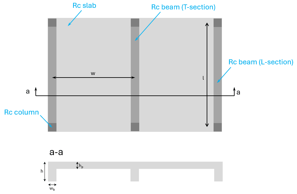
- Height of the beam: \( h = 0.8\,\text{m} \)
- Width of the beam: \( w_b = 0.3\,\text{m} \)
- Height of the slab: \( h_p = 0.25\,\text{m} \)
- Spacing of the beams: \( w = 6\,\text{m} \)
- Span of the beams: \( l = 7\,\text{m} \)
Step #1: Characteristic and design loads
First, we need to calculate the characteristic loads that act on the beam, such as dead load, live load or snow load. We won’t show how to calculate the individual loads here, because each load is an article of its own. You can follow these guides:
The most detailed resource is my e-book Loads on Residential Buildings, where I cover all loads of a whole residential building.
We’ll define the design internal forces later in this article. If you don’t know how to calculate design loads from characteristic loads, check out our detailed guide to load combinations.
Step #2: Concrete and reinforcement properties
These are the material properties we use (the same as in our reinforced concrete beam tutorial, see also concrete and reinforcement properties):
| Property | Value |
|---|---|
| Concrete compression strength | \( f_{ck} = 25\,\text{MPa} \) |
| Concrete tensile strength | \( f_{ctm} = 2.6\,\text{MPa} \) |
| Partial factor in-situ concrete (Denmark) | \( \gamma_c = 1.45 \) |
| Design concrete compression strength | \( f_{cd} = \frac{f_{ck}}{\gamma_c} = 17.2\,\text{MPa} \) |
| Design concrete tensile strength | \( f_{ctd} = \frac{f_{ctm}}{\gamma_c} = 1.8\,\text{MPa} \) |
| Concrete cover | \( c = 30\,\text{mm} \) |
| Reinforcement yield strength | \( f_{yk} = 550\,\text{MPa} \) |
| Partial factor for reinforcement (Denmark) | \( \gamma_s = 1.2 \) |
| Design yield strength | \( f_{yd} = \frac{f_{yk}}{\gamma_s} = 458.3\,\text{MPa} \) |
| Ultimate compressive strain (C12–C50) | \( \varepsilon_{cu3} = 0.35\,\% \) |
| Compressive strain at peak stress (C12–C50) | \( \varepsilon_{c3} = 0.175\,\% \) |
| Factor for the effective height of the compression zone (C12–C50) | \( \lambda = 0.8 \) |
| Factor for the effective strength (C12–C50) | \( \eta = 1.0 \) |
| Design yield strain (reinforcement 550 MPa) | \( \varepsilon_{yd} = 0.208\,\% \) |
| E-modulus concrete | \( E_{cm} = 31476\,\text{MPa} \) |
| E-modulus reinforcement | \( E_s = 200000\,\text{MPa} \) |
You can find many of these material parameters on eurocodeapplied.com.
Step #3: Effective width of the T-section
The effective width of the T-section depends on the static system of the beam and the distance between the beams (EN 1992-1-1 5.3.2.1).
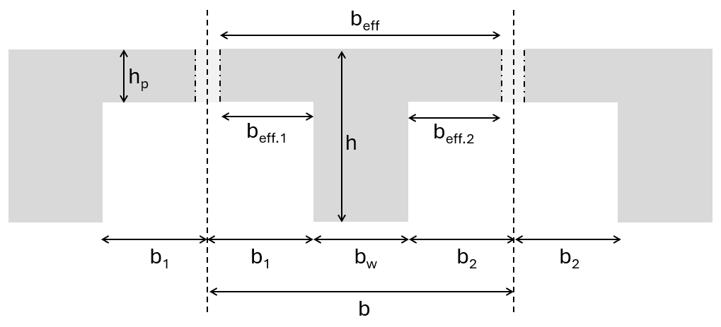
First, we define the distance between the points of zero moment. For a simply supported beam, that’s the span. For continuous beams, it’s less than the span.
$$ l_0 = l = 7\,\text{m} $$
Next, we calculate \( b_1 \), \( b_2 \), \( b_{eff,1} \), \( b_{eff,2} \) and \( b_{eff} \):
$$ b_1 = \frac{w – w_b}{2} = 2.85\,\text{m} $$$$ b_2 = b_1 = 2.85\,\text{m} $$$$ b_{eff,1} = \min\left(0.2 \cdot b_1 + 0.1 \cdot l_0;\; 0.2 \cdot l_0;\; b_1\right) = 1.27\,\text{m} $$$$ b_{eff,2} = b_{eff,1} = 1.27\,\text{m} $$$$ b_{eff} = b_{eff,1} + b_{eff,2} + w_b = 2.84\,\text{m} $$
Step #4: ULS bending verification
The formulas for the bending verification of T- and L-sections are the same as for rectangular sections. The only difference is that for positive moments the effective width can be used for the compression zone, and for negative moments (at the supports of continuous beams) the tension reinforcement should be spread over the effective width.
In this tutorial, we’ll verify the T-section for a positive design moment of 800 kNm.
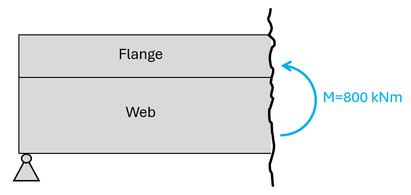
In the bending verification, we design the longitudinal reinforcement of the beam and verify the concrete in the compression zone (see also bending verification of reinforced concrete).
Let’s assume the diameter of the longitudinal reinforcement is \( d_s = 28\,\text{mm} \) and of the stirrups \( d_v = 10\,\text{mm} \). Then the lever arm is:
$$ d = h – c – d_v – \frac{d_s}{2} = 746\,\text{mm} $$
The lever arm is the distance from the outermost concrete fibre in compression to the longitudinal reinforcement that takes up the tension forces. In our example (positive bending moment), we get compression at the top and tension at the bottom.
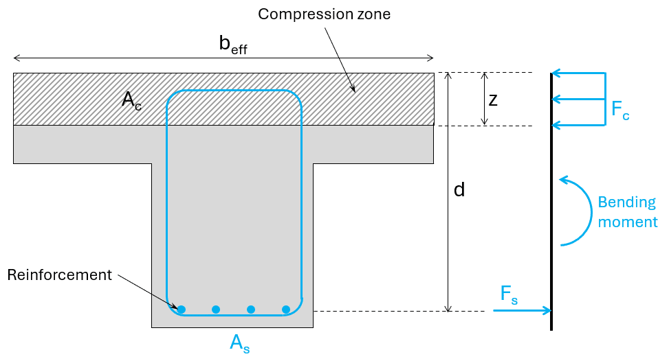
Next, we calculate the required longitudinal reinforcement to take up the tension force with the following formulas:
$$ \mu = \frac{M}{b_{eff} \cdot d^2 \cdot f_{cd}} = 0.029 $$$$ \omega = 1 – \sqrt{1 – 2\mu} = 0.030 $$
Required longitudinal reinforcement:
$$ A_s = \omega \cdot \frac{b_{eff} \cdot d \cdot f_{cd}}{f_{yd}} = 2375\,\text{mm}^2 $$
We picked a rebar diameter of 28 mm, which has a cross-sectional area of:
$$ A_{s,1} = \pi \cdot \left(\frac{d_s}{2}\right)^2 = 615.8\,\text{mm}^2 $$
Next, we calculate the minimum number of rebars we need to fulfil the required reinforcement:
$$ n = \text{ceil}\left(\frac{A_s}{A_{s,1}}\right) = 4 $$
Now, we can calculate the total reinforcement area of 4 rebars with a diameter of 28 mm:
$$ A_s = n \cdot A_{s,1} = 2463\,\text{mm}^2 $$
Let’s also check that the 4 rebars fit into one layer. The clear distance between the bars must be at least \( \max(d_s;\; d_g + 5\,\text{mm};\; 20\,\text{mm}) \) (EN 1992-1-1 8.2), assuming a maximum aggregate size of \( d_g = 16\,\text{mm} \):
$$ s = \frac{w_b – 2 \cdot c – 2 \cdot d_v – n \cdot d_s}{n – 1} = 36\,\text{mm} \ge 28\,\text{mm} \;\rightarrow\; \text{OK} $$
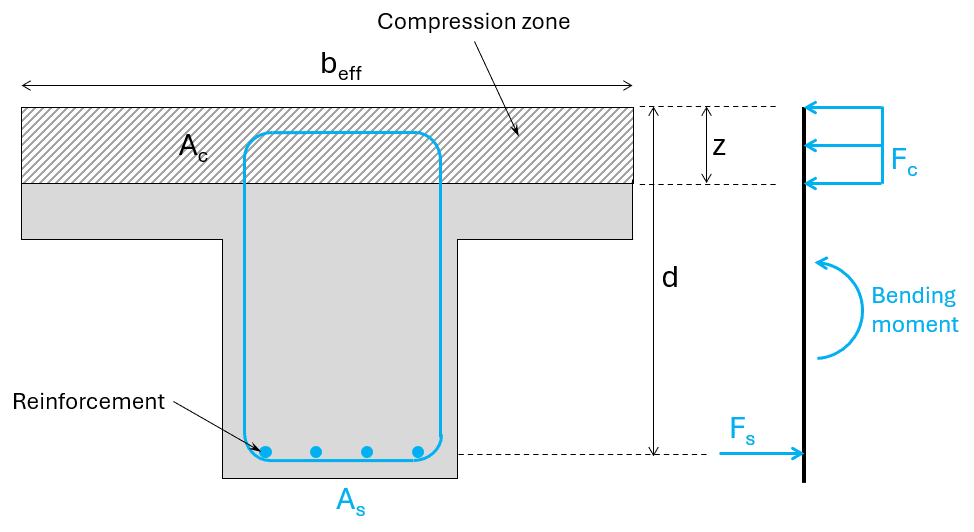
We also need to check that the compression zone lies only in the flange and not partly in the web. If it doesn’t, we can’t use the formulas above.
Creep coefficient:
$$ \varphi(t, t_0) = 2.8 $$
Long-term E-modulus of concrete:
$$ E_{c,eff} = \frac{E_{cm}}{1 + \varphi(t, t_0)} = 8283\,\text{MPa} $$
Long-term ratio of the reinforcement and concrete moduli:
$$ \alpha_s = \frac{E_s}{E_{c,eff}} = 24.1 $$
We find the depth of the neutral axis from the equilibrium of the first moments of area of the tension (steel) and compression areas (see also moment of inertia of a cracked section):
$$ z = \frac{\alpha_s \cdot A_s}{b_{eff}} \cdot \left(-1 + \sqrt{1 + \frac{2 \cdot b_{eff} \cdot d}{\alpha_s \cdot A_s}}\right) = 157.1\,\text{mm} $$$$ h_p = 25\,\text{cm} > z = 15.7\,\text{cm} \;\rightarrow\; \text{OK} $$
The compression zone therefore lies completely in the flange.
As a next step, we verify that the cross-section is neither over- nor under-reinforced. For T-beams, the minimum and maximum reinforcement ratios refer to the web width \( w_b \) (tension zone), while the balanced ratio refers to the compression zone with the effective width \( b_{eff} \).
$$ \omega_{min} = \max\left(0.26 \cdot \frac{f_{ctm}}{f_{yk}} \cdot \frac{f_{yd}}{f_{cd}};\; 0.0013 \cdot \frac{f_{yd}}{f_{cd}}\right) = 0.035 $$
$$ \omega_{bal} = \lambda \cdot \frac{\varepsilon_{cu3}}{\varepsilon_{cu3} + \varepsilon_{yd}} = 0.502 $$
$$ \omega_{max} = 0.044 \cdot \frac{f_{yd}}{f_{cd}} = 1.17 $$
Reinforcement ratio related to the web (tension zone):
$$ \omega_w = \frac{A_s \cdot f_{yd}}{w_b \cdot d \cdot f_{cd}} = 0.293 $$
Verifications:
$$ \omega_w = 0.293 > \omega_{min} = 0.035 \;\rightarrow\; \text{OK} $$$$ \omega = 0.030 < \omega_{bal} = 0.502 \;\rightarrow\; \text{OK} $$$$ \omega_w = 0.293 < \omega_{max} = 1.17 \;\rightarrow\; \text{OK} $$
Finally, we verify the minimum reinforcement according to EN 1992-1-1 9.2.1.1 (9.1N):
$$ A_{s,min} = \max\left(0.26 \cdot \frac{f_{ctm}}{f_{yk}} \cdot w_b \cdot d;\; 0.0013 \cdot w_b \cdot d\right) = 290.9\,\text{mm}^2 $$
Comparing \( A_s \) with \( A_{s,min} \) shows that the minimum reinforcement is less than the reinforcement we get from 4 rebars with a diameter of 28 mm:
$$ A_{s,min} = 290.9\,\text{mm}^2 < A_s = 2463\,\text{mm}^2 \;\rightarrow\; \text{OK} $$
This was only the verification of the bottom longitudinal reinforcement. Don’t forget to also verify the top reinforcement. If you don’t have negative moments, it should at least have the minimum reinforcement.
Step #5: ULS shear verification
The shear verification is exactly the same as for rectangular sections. We explain it in detail in our article on shear verification with shear reinforcement and in this YouTube video on how to verify reinforced concrete beams for shear.
Step #6: SLS crack verification
The crack verification is also exactly the same as for rectangular sections. Check out our reinforced concrete beam design guide to learn how to do it.
Step #7: SLS deflection verification
For the deflection verification, check out our reinforced concrete beam design guide as well.
Final words
That’s how we design reinforced concrete T- and L-beams according to Eurocode 2: calculate the effective width, design the longitudinal reinforcement, check that the compression zone lies in the flange and verify shear, cracks and deflection just like for rectangular beams.
If you want to learn more about reinforced concrete design, check out → Module #3: Structural Design of Reinforced Concrete Slabs, Masonry & RC Walls ←.
In this e-book, I show you step by step how I design reinforced concrete slabs with finite element software and how I design reinforced concrete walls, the same way I do it at work as a structural engineer.
If you don’t want to miss any new structural design tutorials, then subscribe to our free weekly newsletter.
Or subscribe to my YouTube channel for regular updates.
Let’s design better structures together,
Laurin.

Laurin Ernst