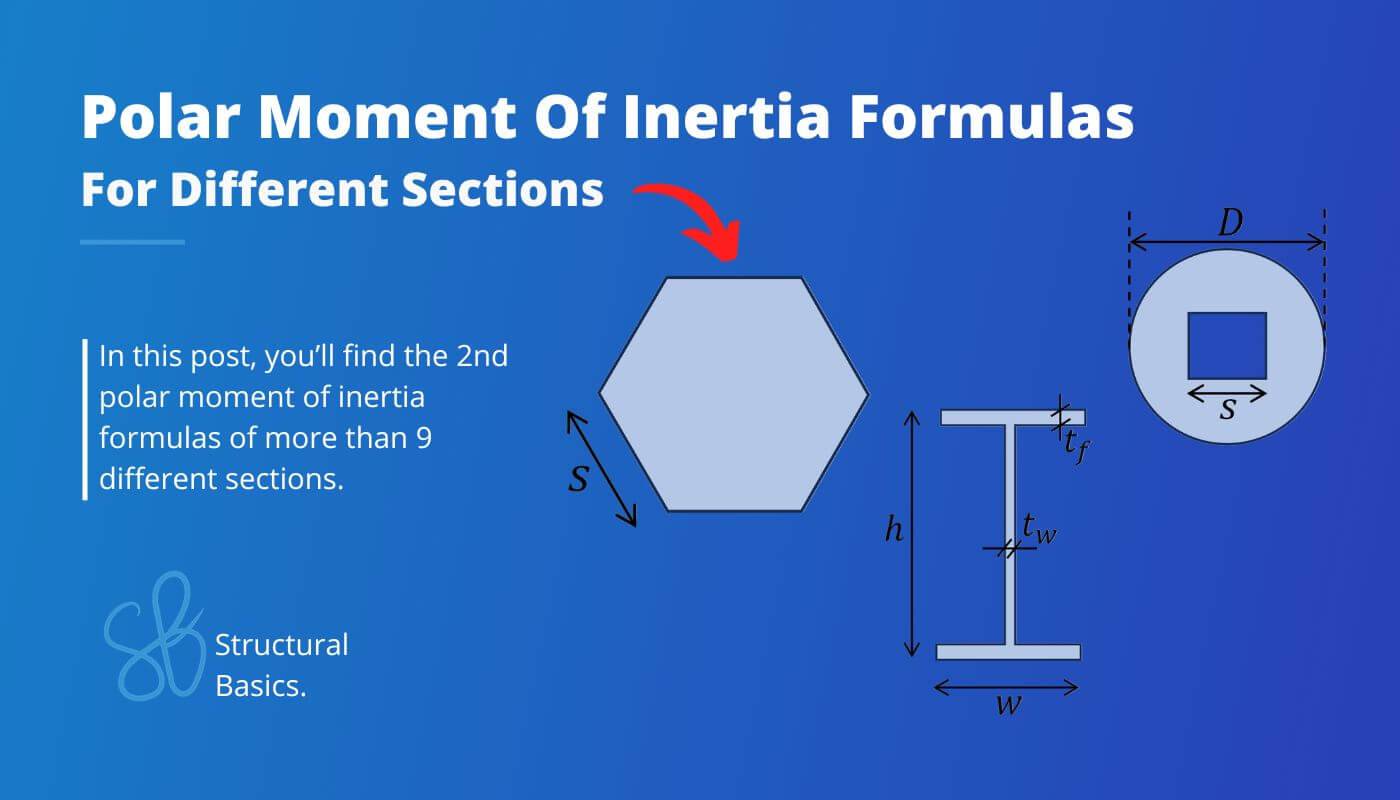
9+ Polar Moment Of Inertia Formulas [2026]
The polar moment of inertia, quantifies an object/section’s resistance to rotational motion about a specific axis.
This property plays an important role in structural and mechanical engineering, ranging from bolted steel connections to complex machinery analysis.
Every shape has a different polar moment of inertia. In this blog post, we’ll show the formulas for different sections, so you don’t have to calculate them yourself.
Let’s get started. 🚀🚀
What Is The Polar Moment Of Inertia?
The second polar moment of inertia, often denoted as Ip or J, is a measure of an object’s resistance to torsional, or twisting, deformation around an axis perpendicular to its longitudinal axis.
It is commonly used in engineering and mechanics to analyse and design structures, components and connections subjected to torsional loads, such as shafts, steel tubes and bolted connections.
Formula Of Polar Moment Of Inertia
The formula for the 2nd polar moment of inertia is the following:
$$I_p = \int \int_{A}^{} r^2 \,dA $$
With,
| dA | Infinitesimal element |
| r | Radial distance to element dA |
I know, I know, we all don’t like integrals. They are just too complicated, right?
So, the formula for the 2nd polar moment of inertia that we all understand better is:
$$I_p = I_y + I_z$$
Where
| Iy | Moment of inertia strong axis |
| Iz | Moment of inertia weak axis |
Now, the formula has become a lot easier. You can check out our blog post about moment of inertial formulas to calculate Iy and Iz quicker.
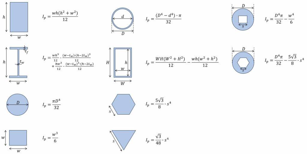
1. I- and H Section
Polar moment of inertia
$I_p = \frac{w \cdot h^3}{12} – \frac{(w-t_w) \cdot (h-2\cdot t_f)^3}{12}$
$ + \frac{(h-2\cdot t_f) \cdot t_w^3}{12} + \frac{2\cdot t_f \cdot w^3}{12}$
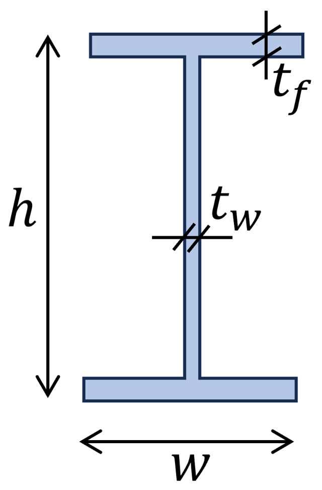
Example calculation
$h$ = 300mm, $b$ = 150mm, $t_f$ = 10mm, $t_s$ = 7m
$I_p = \frac{w \cdot h^3}{12} – \frac{(w-t_w) \cdot (h-2\cdot t_f)^3}{12} + \frac{(h-2\cdot t_f) \cdot t_w^3}{12} + \frac{2\cdot t_f \cdot w^3}{12} $
$I_p = \frac{150mm \cdot (300mm)^3}{12} – \frac{(150mm-7mm) \cdot (300mm-2\cdot 10mm)^3}{12} \frac{(300mm-2\cdot 10mm) \cdot (7mm)^3}{12} + \frac{2\cdot 10mm \cdot (7mm)^3}{12} $
$I_p = 7.59 \cdot 10^7 mm^4$
2. Square Section
Polar moment of inertia
$I_p = \frac{w^4}{6} = 0.1667 w^4$
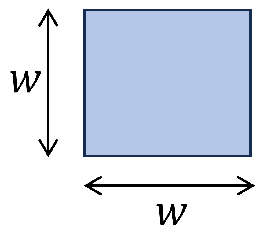
Example calculation
w = 120 mm
$J = \frac{w^4}{6} = \frac{(120mm)^4}{6} = 3.46 \cdot 10^7 mm^4$
3. Rectangular Section
Polar moment of inertia
$I_p = \frac{wh (w^2 + h^2)}{12}$
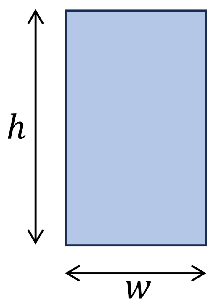
Example calculation
w = 120 mm, h = 240mm
$J = \frac{wh (w^2 + h^2)}{12} = \frac{120mm \cdot 240mm \cdot ((120mm)^2 + (240mm)^2)}{12} = 1.73 \cdot 10^8 mm^4$
4. Circle/ Circular Section
Polar moment of inertia
$I_p = \frac{\pi \dot D^4}{32}$
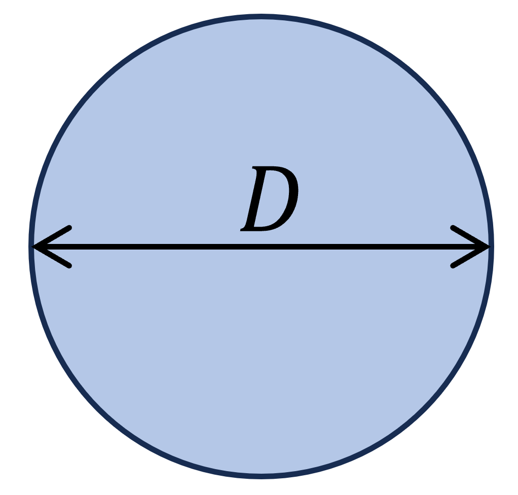
Example calculation
D = 200 mm
$J = \frac{\pi \dot D^4}{32} = \frac{\pi \dot (200mm)^4}{32} = 1.57 \cdot 10^8 mm^4$
5. Circular Tube Section
Polar moment of inertia
$I_p = \frac{\pi}{32} \cdot (D^4 – d^4)$
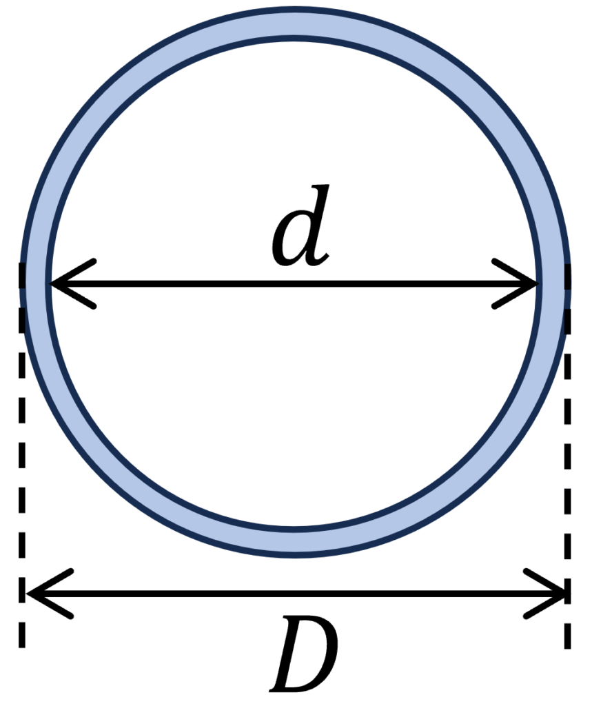
Example calculation
D = 200 mm, d = 180mm
$J = \frac{\pi}{32} \cdot (D^4 – d^4) = \frac{\pi}{32} \cdot ((200mm)^4 – (180mm)^4) = 5.4 \cdot 10^7 mm^4$
6. Circular Section With Square Cutout
Polar moment of inertia
$I_p = \frac{\pi \cdot D^4}{32} – \frac{w^4}{6}$
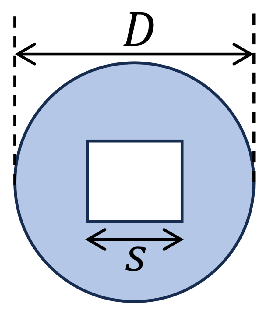
Example calculation
D = 200 mm, w = 100 mm
$J = \frac{\pi \cdot D^4}{32} – \frac{w^4}{6} = \frac{\pi \cdot (200mm)^4}{32} – \frac{(100mm)^4}{6} = 1.4 \cdot 10^8 mm^4$
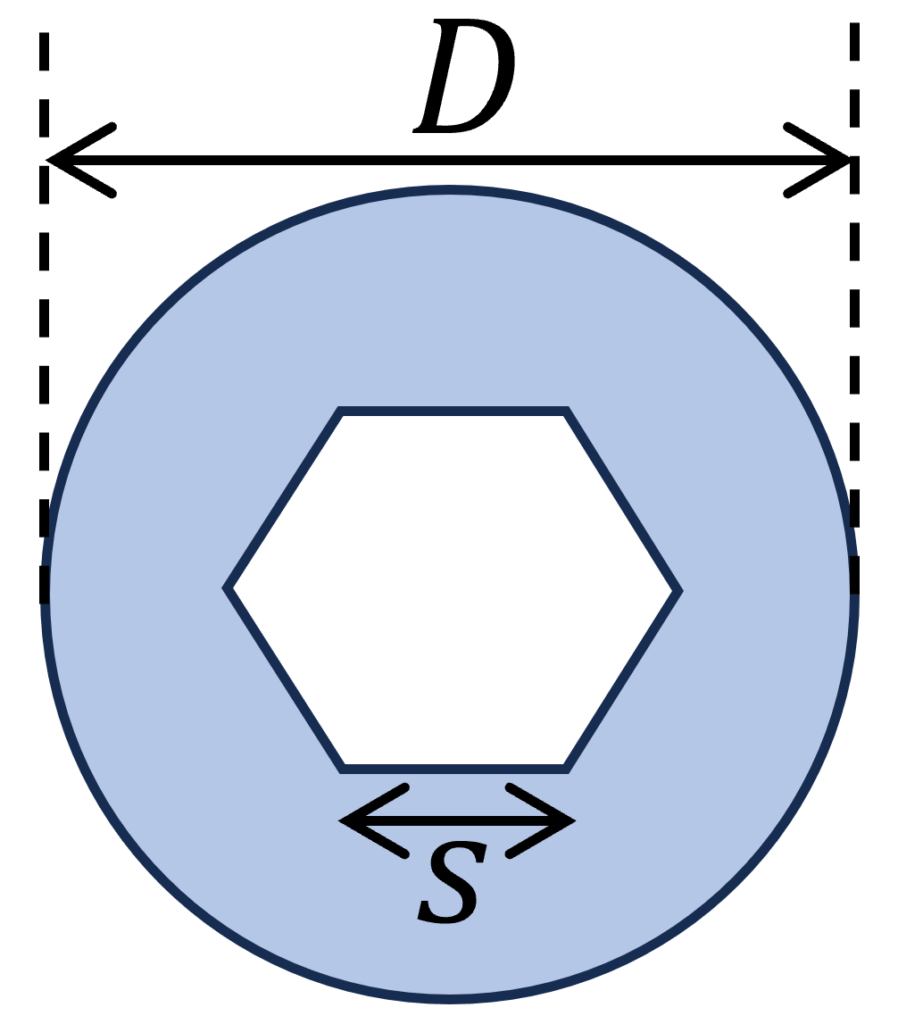
7. Hexagon Section
Polar moment of inertia
$I_p = \frac{5 \cdot \sqrt{3}}{8} \cdot s^4$
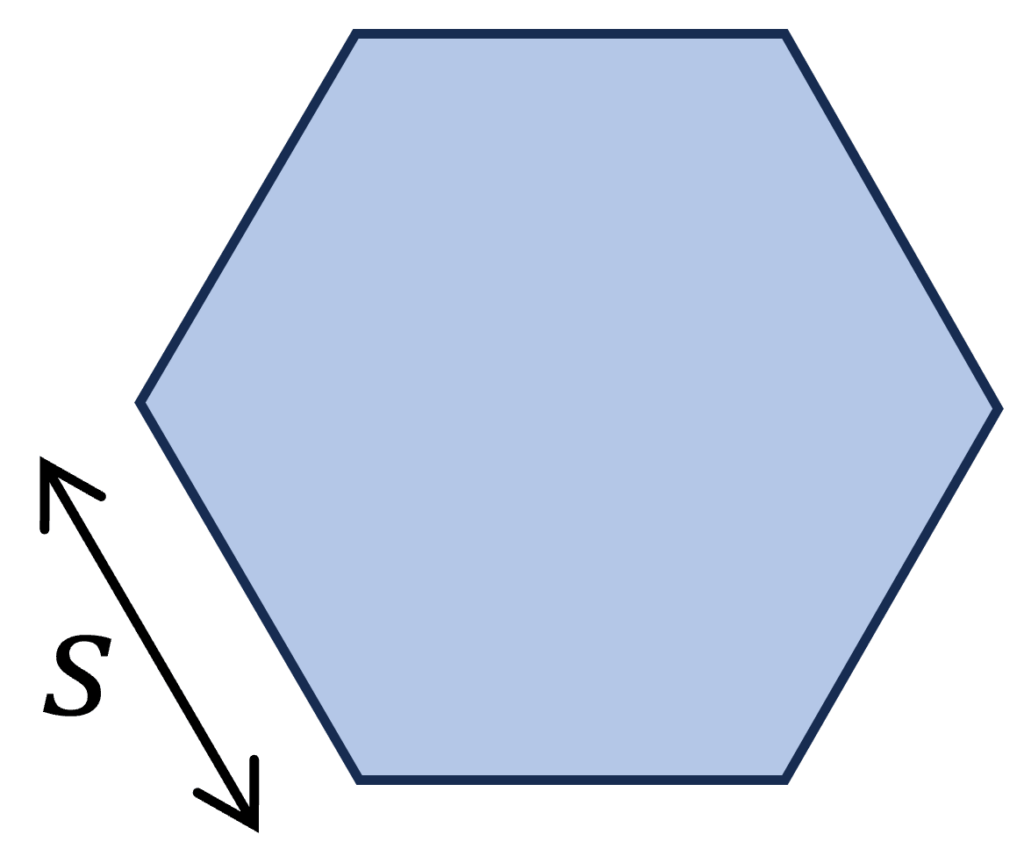
Example calculation
D = 200 mm, w = 100 mm
$J = \frac{5 \cdot \sqrt{3}}{8} \cdot s^4 = \frac{5 \cdot \sqrt{3}}{8} \cdot (100mm)^4 = 1.08 \cdot 10^8 mm^4$
8. Hollow Rectangular Section
Polar moment of inertia
$I_p = \frac{WH (W^2 + H^2)}{12} – \frac{wh (w^2 + h^2)}{12}$
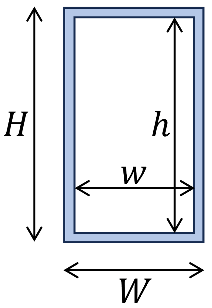
Example calculation
H = 240 mm, W = 120 mm, h = 200 mm, w = 90 mm
$J = \frac{WH (W^2 + H^2)}{12} – \frac{wh (w^2 + h^2)}{12} = \frac{120mm \cdot 240mm ((120mm)^2 + (240mm)^2)}{12} – \frac{90mm \cdot 200mm ((90mm)^2 + (200mm)^2)}{12} = 1.0 \cdot 10^8 mm^4$
9. Triangular Section
Polar moment of inertia
$I_p = \frac{\sqrt{3}}{48} \cdot s^4$
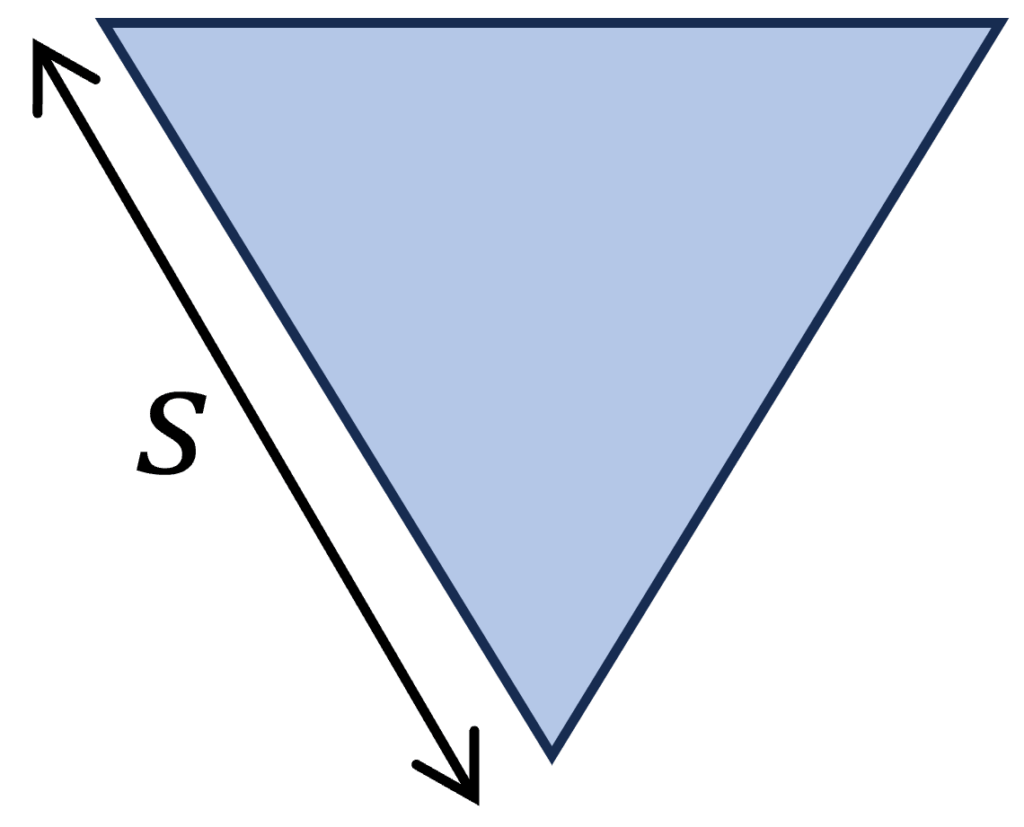
Example calculation
s = 100 mm
$I_p = \frac{\sqrt{3}}{48} \cdot s^4 = \frac{\sqrt{3}}{48} \cdot (100mm)^4 = 3.6 \cdot 10^6 mm^4$
10. Circular Section With Socket Head Cutout
Polar moment of inertia
$I_p = \frac{\pi D^4}{32} – \frac{5 \sqrt{3}}{8} \cdot s^4$
Example calculation
D = 300 mm, s = 100 mm
$I_p = \frac{\pi D^4}{32} – \frac{5 \sqrt{3}}{8} \cdot s^4$
$I_p = \frac{\pi (300mm)^4}{32} – \frac{5 \sqrt{3}}{8} \cdot (100mm)^4$
$I_p = 6.9 \cdot 10^8 mm^4$
Conclusion
The polar moment of inertia is an important parameter in structural design. Therefore, it’s recommendable to know how to calculate it for different cross-sections. You do that by adding Iy and Iz together.
In the following blog posts, we show step-by-step, how to calculate these moments of inertias.
If you are new to structural design, then check out our design tutorials about other structural elements. 👇👇
Do you miss any 2nd polar moment of inertia formula for any shape or cross-section that we forgot in this article? Let us know in the comments. ✍️✍️
![12 Types of Columns in Buildings [The MOST Used]](https://www.structuralbasics.com/wp-content/uploads/2022/11/Types-of-columns-and-what-a-column-is-1-768x439.jpg)
![How to Calculate The Cross Sectional Area? [A Beginner’s Guide]](https://www.structuralbasics.com/wp-content/uploads/2023/01/how-to-calculate-the-cross-sectional-area-768x439.jpg)
![What Is A Roof Joist? [2026]](https://www.structuralbasics.com/wp-content/uploads/2023/04/What-is-a-roof-joist-768x439.jpg)